

Page 1
OA-72C
MANUFACTURER'S STATEMENT
MANUFACTURER'S STATEMENT
Read this operation manual carefully before use to ensure proper operation of this product.
Failure to read this operation manual may cause improper operation and may result in serious injury or death of
a person.The meanings of the symbols are as follows.
5919371 NOV 2014
WARNING
CAUTION
NOTE
NOTE
1. This product is a non-contact switch intended for ceiling mount for use on automatic sliding doors.
Do not use for any other applications.
2. When setting the sensors detection area, make sure that there is no traffic around the installation site.
3. Before turning the power ON, check the wiring to prevent damage or malfunction of equipment connected
to the product.
4. Only use the product as specified in the operation manual provided.
5. Be sure to install and adjust the sensor in accordance with the local laws and standards of the country in
which the product is installed.
6. Before leaving the installation site make sure that the product is operating properly and instruct the building
owner/operator on proper operation of the door and the product.
7.The product settings can only be changed by an installer or service engineer. When changed, the
changed settings and the date shall be registered in the maintenance logbook accompanying the door.
Danger of electric shock
NOTE
The following conditions are not suitable for sensor installation.
-Fog or exhaust emission around the door
-Wet floor
-Vibrating header or mounting surface
-Moving objects, steel plate, emergency lights or illumination in the detection area or in vicinity
-Highly reflecting floor or highly reflecting objects around the door
SPECIFICATIONS
Model
Cover color
Mounting height
Detection area
Detection method
Depth angle adjustment
Width angle adjustment
Power supply
Power consumption
Operation LED
NOTE
The specifications herein are subject to change without prior notice due to improvements.
Disregard of the warning symbol can cause improper operation which may cause death
or serious injury.
Disregard of the caution symbol can cause improper operation which may cause injury of a
person or damage the object.
Special attention is required to the section of this symbol.
WARNING
: OA-72C
: Silver
: 2.0 (6'7") to 4.0m (13'1")
: See DETECTION AREA
: Active Infrared Reflection
: -15° to +10°
: -10° to +10°
: 12 to 24 VAC (±10%)
12 to 30 VDC (±10%)
: < 1.5W (< 5 VA at AC)
: Green / stand-by
Red / 1st row detection
Orange / 2nd to 5th rows detection
Do not wash, disassemble, rebuild or repair the sensor, otherwise
it may cause electric shock or breakdown of the equipment.
Output
Output hold time
Response time
Operating temperature
Weight
Accessories
: Form C relay
50V 0.3A max.(resistance load)
: Approx. 0.5 sec.
: <0.3 sec.
: -20°C to +55°C (-4°F to 131°F)
: 320g (11.2oz)
: 1 Cable 3m (9'10")
1 Operation manual
1 Mounting template
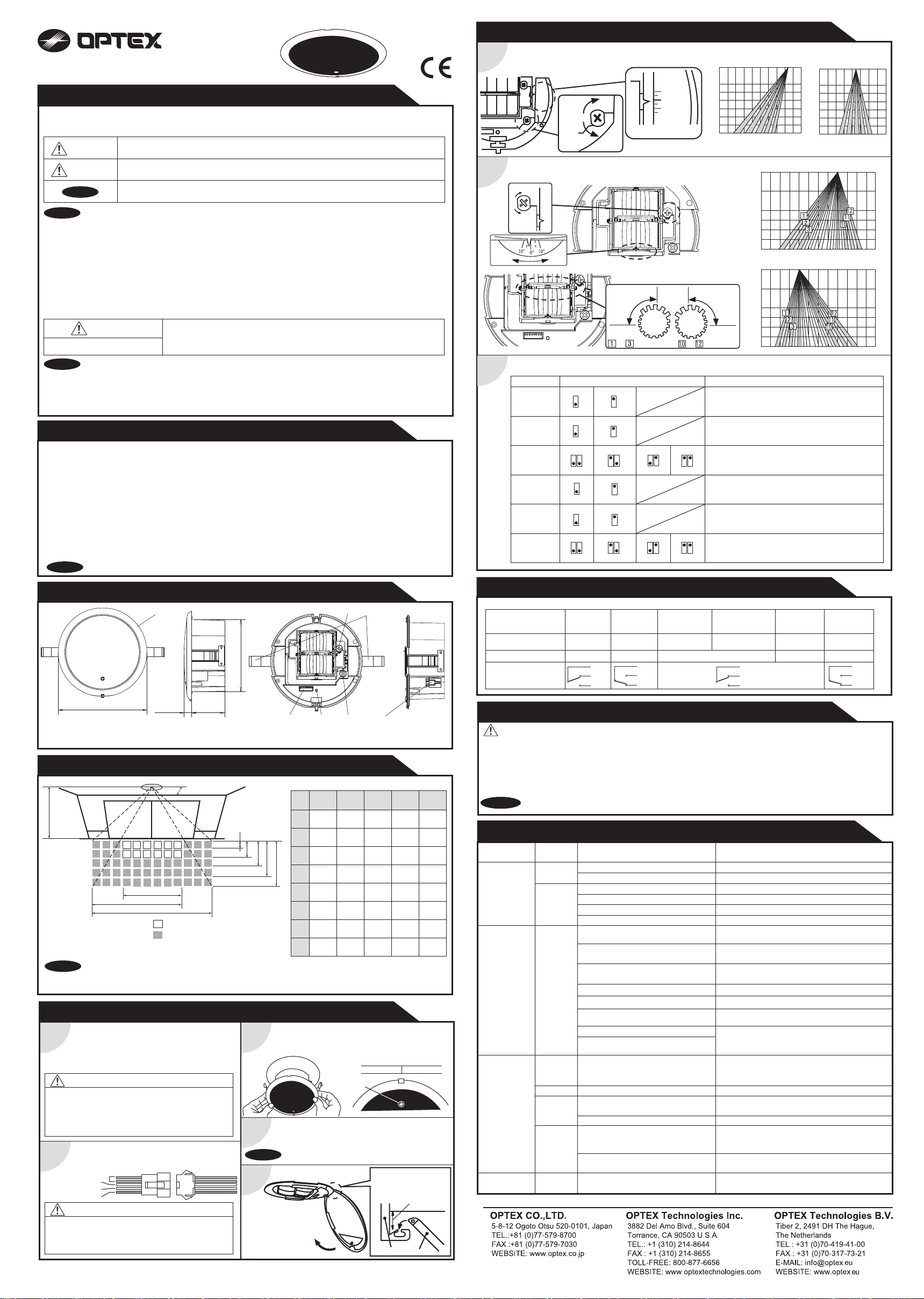
ADJUSTMENTS
Area depth angle adjustment
1
Door Side
Width detection area adjustment
2
Left
Right
Right Left
Dipswich setting
3
Function
Sensitivity
Mounting
height
Presence
timer
Frequency
Snow mode
Area
adjustment
Deep
Shallow
Low
1
2 to 3m
2
30sec
43
Setting1
5
OFF ON
6 6
5 rows
87
+10°
-10°
-15°
Depth angle scale
Wide Wide
Narrow Narrow
to elimination to elimination
Setting
High
1
2.7 to 4m
2
60sec
Setting2
4 rows
180sec
43
5
3 rows
87
600sec
43
87
43
2 rows
87
10° to the outside
2.0m
3.0m
4.0m
4.0m 3.0m 2.0m 1.0m
-15° to the door side
2.0m
3.0m
4.0m
0
2.0m 1.0m -1.0m
0
10° to left
2.0m
3.0m
4.0m
4.0m 3.0m 2.0m 1.0m 0 1.0m 2.0m
10° to right
2.0m
3.0m
4.0m
Comment
Set the sensitivity according to the mounting height.
Adjust the sensitivity according to your risk
assessment.
Set the sensitivity according to the mounting height.
Adjust the sensitivity according to your risk
assessment.
All rows include presence detection function.
When using more than two sensors close to each
other, set the frequency different for each sensor.
Set this switch to ON if the sensor is used in a
region with snow or a lot of insects.
Adjust the area detection depth by selecting the
dipswitches.
4.0m3.0m2.0m2.0m 1.0m1.0m 0
OUTER DIMENSIONS AND PART NAMES
155(6 2/16”)
1. Mounting clips
2. Connector
(3)
13(1/2”)
3. Cover
4. Depth adjustment screw
mm(inch)
58(2 5/16”)
main unit
125(4 15/16”)
(7)
5. Width adjustment screw
6. Operation indicator
DETECTION AREA
300mm(11.8”)
A
1st row
2nd row
3rd row
4th row
5th row
Sensor setting
Depth angle adjustment : 0°
NOTE
*The values of the chart above is of the emitting spots, but not of the detection area.
The actual detection area may become smaller depending on the ambient light, the color / material of the
object or the floor as well as the entry speed of the object.
G
H
I
: Emitting spots
: Emitting spots (can be eliminated)
B
C
D
A
B
C
D
E
F
E
F
G
H
I
INSTALLATION
1. Affix the mounting template at the desired
mounting position.
1
2. Drill a mounting hole.
(recommended diameter : ø130mm (5”))
3. Remove the mounting template.
CAUTION : Risk of getting caught.
Make sure to affix the mounting template as
described in the above chart, otherwise it can be
dangerous since there may be no presence detection
area around the threshold.
Remove the cover from the sensor.
Plug the connector of the cable to the connector of the
2
sensor.
Gray : Power supply
White : COM.
Yellow : N.O.
Green : N.C.
WARNING : Danger of electric shock.
Before starting the procedure, ensure that the power is
turned OFF. When passing through the cable to the
hole, make sure not to tear the shield, otherwise it may
cause electric shock or breakdown of the sensor.
1. Install the sensor with cover, keeping the direction of
operation indicator towards the door.
3
2. Press the mounting clips against the sensor to place the
sensor into the mounting hole.
Supply power to the sensor. Adjust the detection area and
set the dipswitches. (See ADJUSTMENTS)
4
NOTE
To enable the presence detection, do not enter the
detection area for 10 seconds after supplying the power.
Mount the cover on the sensor.
5
(6) (4)
2.20
(7'3")
0.13
(5.1")
0.37
(1'3")
0.63
(2'1")
0.93
(3'1")
1.24
(4'1")
1.08
(3'7")
1.65
(5'5")
2.25
(7'5")
Operation
indicator
(5)
2.50
(8'2")
0.15
(5.9")
0.43
(1'5")
0.72
(2'4")
1.06
(3'6")
1.41
(4'8")
1.24
(4'1")
1.88
(6'2")
2.57
(8'5")
(1)
(2)
7. Dipswitch
3.00
3.50
(9'10")
(11'6")
0.18
0.21
(7.1")
(8.3")
0.60
0.51
(1'12")
(1'8")
1.01
0.87
(3'4")
(2'10")
1.49
1.28
(4' 11")
(4'2")
1.98
1.70
(6'6")
(5'7")
1.48
1.73
(4'10")
(5'8")
2.25
2.63
(7'5")
(8'8")
3.08
3.59
(10'1")
(11'9")
Door
Mount the cover by
making a small gap
between sensor and
ceiling.
Main unit
[m(feet,inch)]
4.00
(13'1")
0.24
(9.4")
0.69
(2'3")
1.16
(3'10")
1.71
(5'7")
2.26
(7'5")
1.98
(6'6")
3.00
(9'10")
4.10
(13'5")
Cover
CHECKING
Check the operation according to the chart below.
Entry
Status
Operation LED
Output
Power off
None
Outside of
detection
area
-
Stand-by
Green Green
COM
N.O.
N.C.
Entry into 3rd,
4th or 5th row
detection active
COM
N.O.
N.C.
Motion
Entry into
2nd row
Motion/Presence
detection active
Orange
COM
N.O.
N.C.
Entry into
1st row
Presence
detection
Red
INFORM BUILDING OWNER / OPERATOR OF THE FOLLOWING ITEMES
WARNING
NOTA
NOTE
1. Wipe the detection window with a damp cloth.
Do not use any cleaner or solvent.
2. Do not wash the sensor with water.
3. Do not disassemble, rebuild or repair the sensor yourself, otherwise an electric shock may occur.
4. When an operation LED blinks green, contact your installer or service engineer.
5. Always contact your installer or service engineer when changing the settings.
6. Do not paint the detection window.
1. When turning the power on, always walk-test the detection area to ensure proper operation.
2. Do not place any objects that move or emit light in the detection area. (e.g. plant, illumination, etc.)
TROUBLESHOOTING
Problem
Door does not
open when a
person enters
the detection
area.
Door opens
when no one
is in the
detection area.
(Ghosting)
Door remains
open
Door remains
closed
Operation
LED
None Power supply voltage. Set to the stated voltage.
Unstable
Unstable
Red
orange
Proper
Fast
green
blinking
Slow
green
blinking
Proper
Wrong wiring or connection failure.
Wrong detection area positioning.
Sensitivity is too low.
Short presence detection timer.
Dirty detection window. Wipe the detection window with a damp cloth.
The detection area overlaps
with that of another sensor.
The detection area overlaps
with the door / header.
Reflecting objects in the detection area.
Or reflecting light on the floor.
Sensitivity is too high. Set the sensitivity lower.
It snows.
Objects that move or emit light in the
detection area.
Wet floor. Check the installation condition referring to
The exhaust emission or fog penetrate
into the detection area.
Sudden change in the detection area.
or
Wrong wiring or connection failure.
Sensitivity is too low.
Sensor failure
Signal saturation
The detection area overlaps with
the door / header.
Wrong wiring or connection failure.
Possible cause
Possible countermeasures
Check the wires and connector.
Check ADJUSTMENTS 1 & 2.
Set the sensitivity higher.
Set the presence detection timer longer.
Check ADJUSTMENTS 3.
Adjust the detection area to "deep" (outside).
Remove the objects.
Set the snow mode to ON.
Remove the objects.
MANUFACTURE’S STATEMENT on the reverse
side.
Check ADJUSTMENTS 3.
If the problem still persists, hard-reset the sensor.
(turn the power OFF and ON again.)
Check the wires and connector.
Set AIR area width to “wide”.
Wipe the detection window with a damp cloth.
Contact your installer or service engineer.
Remove highly reflecting objects from the detection
area or lower the sensitivity or change the area
angle.
Adjust the detection area to "deep" (outside).
Check the wires and connector.
Outside of
detection
area
Stand-by
COM
N.O.
N.C.
 Loading...