

Optex MX-40QZ, MX-50QZ, MX-40PI, MX-40PT Owner's Manual
nEASY INSTALLATION
•Easy Wiring Knockout
•Wiring Guide
•·Spare Terminal [MX-40QZ/50QZ/40PT Only]
•Tamper Terminal [MX-40QZ/50QZ/40PT Only]
•·D.L. Terminal [MX-40QZ(BE)/50QZ(BE) Only]
•Wide Wiring Space
nFEATURES
•40ft.×40ft.(12m×12m)Wide Angle [MX-40 Series]
•50ft.×50ft.(15m×15m)Wide Angle [MX-50 Series]
•QUAD Zone Logic
•Patented Multi-focus Lens
•Improved Sealed Optics
•Temperature Compensation Logic
•Pet Immunity [MX-40PI/PT Only]
(See Section 5 for Pet Immunity)
nFUNCTION
•Selectable Pulse Count(2 or 4)
•LED ON/OFF
•Tamper Switch [MX-40QZ/50QZ/40PT Only]
•Microwave Range Selector(LONG or SHORT)
nOPTION
•FA-3 Wall & Ceiling Mount Bracket
(Horizontally ±45°& Vertically 0°to-15°)
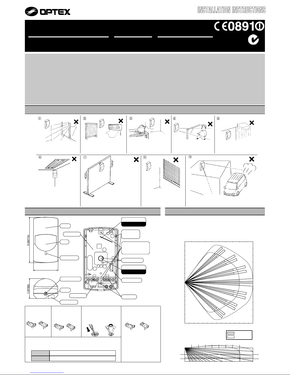
2. DESCRIPTION,OPERATION and DIMENSIONS
TAMPERSP
DL
ALARM
Corner mount
knockout
Wiring knockout
P.C.B. unit
Tamper switch
Terminals
2.44(62)
Cover
LED Indicator
Lens
Base
Wiring guide
Mounting knockout
(Pitch=3.29"/83.5mm)
(Pitch=3.58"/91.0mm)
Fastening screw
inch(mm)
3. DETECTION AREA
WIDE ANGLE
n
TOP VIEW
n
SIDE VIEW
1. INSTALLATION HINTS
Use the pin switch
for Pulse Count
Selection ( 2 or 4 ).
Use the pin switch
for LED ON/OFF .
n LED ON/OFF
n PULSE COUNT
With PET IMMUNITY&TAMPER
MX-40PT
With PET IMMUNITY
MX-40PIMX-40QZ MX-50QZ
PASSIVE INFRARED and MICROWAVE
COMBINATION DETECTOR
P.C.B. hook
MX-40 AREA
MX-50 AREA
30
35
25
50 ft
35
30
0
10
9 12
8 ft
15m
50 ft
25
9
4
S
2
0
2
5
10
2015
20
6
2.2m
0
1510
5
0
3
3
4
S
15m
40 45
12
40
45
5
15
20
S
5
10
15
20
25 ft
8m
25 ft
8m
1.5m
3.0m
2.4m
5 f
t
7.5 ft
10 ft
No.59-0967-0 0009-25
N219
4
2
OFF
ON
n
D.L. TERMINAL D.L. TERMINAL
D.L. TERMINAL D.L. TERMINAL
D.L. TERMINAL
(MX-40QZ(BE),MX-50QZ(BE) Only)
LED can be enabled or disabled remotely from control panel by D.L. terminal.
Place jumper pin switch in OFF position.
n
MICR
OO
OO
OWAVE RANGE
LONG
SHORT
n
EASY WIRING KNOCKOUTS
Press firmly with a screwdriver to
open.Enlarge the hole according
to size of wire.
LED Enabled Connect D.L. terminal to common ground(with detector).
LED Disabled No ground to D.L. terminal (open circuit).
Avoid
Curtain,Screen,etc.
blocking detection area.
Avoid vapor or high
humidity that can cause
condensation.
Avoid direct sunlight.
Do not install outdoors.
Do not aim towards outside areas where there is
frequent movement.
Do not mount in unstable location
where vibration or shock may
affect the detector.
Do not install unit near
fluorescent lights.
Avoid mounting detector where
movement of Fans or Air
Conditioning can be detected.
Do not aim detection area
towards equipment which
continually moves in the
detection area (i.e.curtain,
blinds).
P.I.R. Sensor
Do not touchDo not touch
Do not touchDo not touch
Do not touch!
Do not touchDo not touch
Do not touchDo not touch
Do not touch!
Microwave Sensor
Select RANGE SELECTOR
according to the room size.
(SHORT or LONG)
MX-40 Series
Select RANGE SELECTOR
"SHORT" when it's used with 24ft
(7 m)square and Smaller room.
MX-50 Series
Select RANGE SELECTOR
"SHORT" when it's used with 34ft
(10m)square and Smaller room.
18mA (max.) at 12VDC 20mA (max.) at 12VDC
1. Pet Immunity is most effective on the following sized
animals:Rodents = 0 to 4 inches high
Cats and small to medium sized dogs = 0 to 16 inches
high at normal room temperature.
2. Installation Instructions
a. Mount between 7 and 8 ft. (For better immunity,
especially for medium sized dogs, mount as close
to8ft. as possible.)
b. Do not angle detector towards the ground or use the
angle bracket. Mount flat on the wall or in the corner.
c. For best pet immunity, limit the detectors field of view
to30 ft. maximum in any direction.
d. For rodents
If any shelves within 15 ft.of the detector have a
height that comes wihtin 2.5 ft.below the mounting
height of the detector and rodents can access these
areas, pet immunity will be reduced. Please select
mounting location of detectors carefully to avoid this
situation.
e. For cats and dogs (16 inches in height or less at
normalroom temperature) When a dog jumps up on
desks, the detector may detect it. Adjust detection
area to avoid such places.
f. For cats
If there are cats, any shelves in the detection area will
reduce pet immunity.
g. Pulse Count 4 is not required for Pet Immunity
applications.Use 4 pulse only in harsh environment.
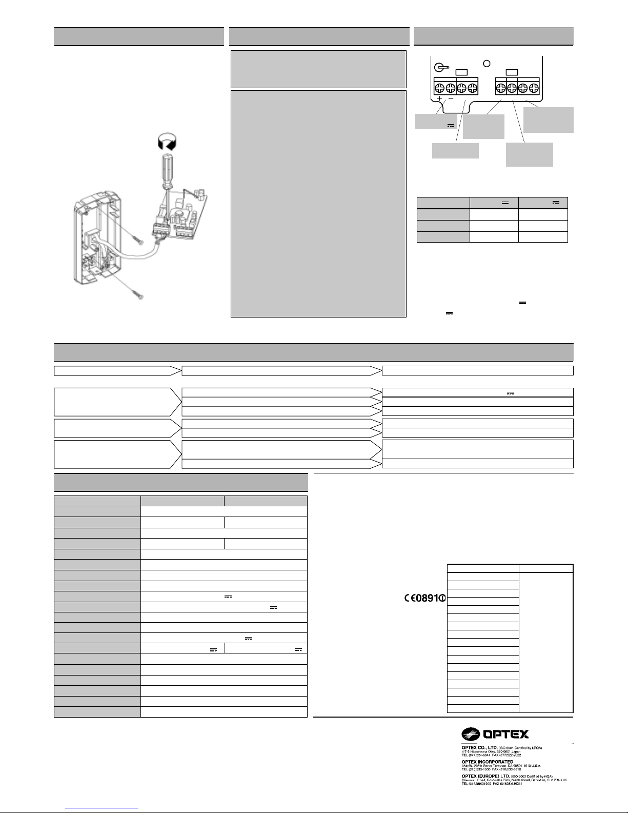
Power wires should not exceed
the following lengths.
When using two or more units on one wire, the
maximum length is obtained by dividing the maximum
wire length listed above by the number of units used.
PROBLEM
REMEDYPROBABLE CAUSE
Correct the voltage supply to 9.5-16VDC .
LED does not light.
See Section 3.
Turn on the Switch. (See Section 2 )
Incorrect power supply voltage.(disconnection, low voltage)
Incorrect detection area.
LED switch is OFF.
Moving object within area. (curtain,wall hanging, etc.)
LED lights even though no
person is within area.
Remove the source from area, or change location of detector.
Remove object from detection area, or change location of detector.
Rapid temperature changes within area.(heater,air-conditioner, etc.)
7. TROUBLE SHOOTING AND MAINTENANCE
8. SPECIFICATIONS
Faulty wiring.
Wire correctly.
Check load of output.
The unit needs repair or replacement.
LED lights but signal is not sent.
Relay contact is stuck or damaged due to overloading.
6. WIRING
*UL requires MX-40QZ,50QZ,40PI,40PT to be
connected to a UL listed power supply capable of
providing a nominal input of 12VDC , 20mA(max.)
(at 12VDC )and battery standby time of 4 hours.
*The equipment shall be installed in accordance with
the National Electrical Code, NFPA 70.
*These features have been tested by Underwriters
Laboratories.
5. PET IMMUNITY (MX-40PI/40PT Only)
*Specifications and design are subject to change without prior notice.
2140' (650m)
3400' (1020m)
5300' (1S00m)
WIRE GAUGE 12VDC
1070' (320m)
1 700' (510m)
27 00' (820m)
14VDC
AWG 22( 0.33mm )
2
2
AWG 20( 0.52mm )
2
AWG 18( 0.83mm )
4.INSTALLATION
a.Loosen fastening screw and remove cover.
b.Release hook at bottom of P.C.B.unit. Remove
P.C.B. unit from base.
c.Route wires through knockouts along the wiring
guide on the rear side of base. Mount base with
supplied screws. When small animal immunity is
required, refer to Section 5.When using a
bracket,check matching knockout positionbefore
opening mounting hole.
d.Wire according to Section 6.
e.Fix P.C.B.unit into base. Supply power. Allow 1
min. to warm up.
f.Conduct walktest and make adjustments.
(Section 2) Fit cover using fastening screw.
FCC Notice : This equipment has been tested and found to comply with the limits for
a field disturbance sensor, pursuant to Part 15 of the FCC Rules. The user is
cautioned that changes or modifications not expressly approved by OPTEX could
void the user's authority to operate this equipment.
TAMPERSP
DLALARM
DL TERMINAL
[MX-40QZ(BE)/
50QZ(BE) Only]
TAMPER( N.C. )
[MX-40QZ/50QZ/
40PT Only]
SPARE
[MX-40QZ/50QZ/
40PT Only]
ALARM OUTPUT
( N.C. )
POWER INPUT
(9.5-16VDC )
Pulse Count
Warm up period
Power input
Current draw
Weight
Operating temperature
Environmental humidity
Microwave Frequency
RF interference
D.L. Terminal
Approx. 20 sec 2 or 4
Approx. 1 min
9.5-16VDC
3.9 oz (110g)
-14°F - +131°F (-10 - +55°C)
95% max.
2.45GHz
No Alarm 20V/m
See Section 2
MODEL
Detection method
Coverage
Detection zones
Mounting Height
Sensitivity
Detection speed
LED Alarm Ind i cat er
Alarm period
Alarm output
Tamper switch
Passive Infrared and Microwave
40ft×40ft(12m×12m) 85°wide 50ft×50ft(15m×15m) 85°wide
78 zones(PIR)
5-8ft (1.5-2.4m) 7.5-10ft (2.2-3.0m)
3.6°F ( 2°C) at 2ft/sec (0.6m/sec)
1-5ft/sec (0.3-1.5m/sec)
Switch-able ON/OFF
Approx. 2.5 sec
N.C. , 28VDC 0.2A max.
N.C. , Open when cover is removed. (N.C. , 28VDC 0.1A max.)
MX-50QZ
MX-40QZ/PI/PT
This unit is designed to detect movement of an intruder and activate an alarm
control panel. Being only a part of a conplete system,we cannot accept
responsibility for any damages or other consequences resulting from an
intrusion.The following statement will be provided with the equipment as required
by Article 6.3 of the R&TTE Directive , 1999/5/EC.
The Optex MX-40 and MX-50 are in conformity with all essential requirements of
the R&TTE Directive (1999/5/EC). This equipment has been assessed to the
following standardsW
I-ETS 300 440:December 1995
ETS 300 683:June 1997
EN 60950: 1992, Incl Amdt 1-4, 11
This product is marked with
which signifies conformity with Class II
product requirements specified in the
R&TTE Directive.
The following table indicates the areas
of intended use of the equipment and
any known restrictions. For countries
not included in this list, please consult
the responsible Spectrum Management
Agency.
NOTE
Country of intended use Restrictions
Austria
Belgium
Denmark
Finland
France
Germany
Greece
Ireland
Italy
Luxembourg
The Netherlands
Spain
Sweden
United Kingdom
Other non EU : Iceland
Norway
Switzerland
2.450GHz
 Loading...