

Page 1
Wireless Video Intercom
IVP-DU(G)
(Door Camera Unit)
Installation Instructions
The performance of the system may be affected when mounting the unit in the
following environments.
- Places that are constantly experiencing vibrations or shocks.
- Near a source of hydrosulfuric fumes, phosphorus fumes, ammonia, sulphur,
carbon dust and any acidic or noxious materials.
- An enclosed space that may cause sounds to echo
- Where rain or water may directly hit the unit.
Please also note that the video image may be seriously impaired where the camera
faces directly into the sun, and also in the following situations.
Location where the background is primarily occupied by the sky, such as in
the upper floor of an apartment building.
Location which has an adjacent white wall that will directly reflect sunlight.
Location that receives direct bright sunlight.
IVP-DU(G) features
Adjustable Camera Angle
Battery Operation Capability (for 1 year*1)
Auto Day(Color) / Night(IR) Vision
Max 2 Units in a System
Fluorescent Push Button
AC/DC (10~24V) Adaptable
Splash Proof for Rain and Outdoor Condition*
2
*1 calculation based on operations for 10sec times 3 activations per a day
*2 IPX4 Operating Temparature -20 to 50 degC (-4 F to 122 degF)
IMPORTANT NOTICE
1.
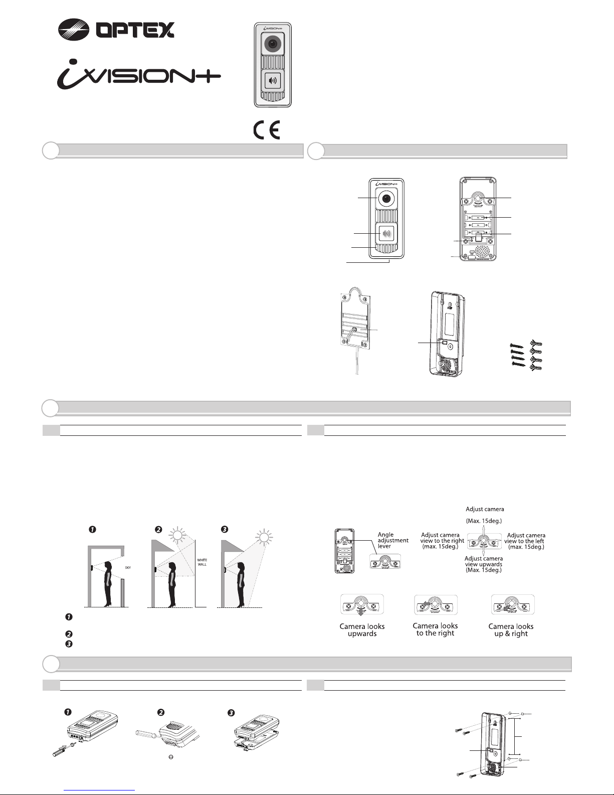
PARTS IDENTIFICATION
2.
Operations under harsh environments such as out of warranted temperature,
rapid temperature change, high humidity, constant moisturization may cause the
unit to malfunction.
Electronic device such as TVs, Radios, PCs, Microwave ovens or any other device
with an electric motor may cause the unit to malfunction.
Impact or shocks can cause severe damage to the unit. Please handle the unit
with care and operate without exerting strong forces.
Transmission range of communication between units may decrease under
the following conditions.
- Any unit is installed on a metal surface.
- Presence of reinforced concrete, steel doors or other metal construction
materials between units.
- Places near strong radio sources such as broadcast stations or substations.
Location of Installation is critical to optimize image quality captured by the unit.
Images will be impaired if the ambient backlight is very strong.
Please study the installation environment according to this installation instruction.
- The video image is displayed in color during daytime or in well-lit area, but it is
displayed in black and white at night or in a dark area.
Old and new batteries may not be mixed. Do not use lithium batteries
for IVP-DU. Leakage or possible explosion can occur.
- When Door Camera Unit Low Battery Indicator blinks on HU1,
please replace batteries.
CHOOSING LOCATION
3.
Cable Hole
Screws & Anchors
Wall Mounting BaseBattery Cover
3-1
Places to Avoid
3-2
Position and Field of View
IVP-DU (Door Camera Unit) should be mounted at a position where visitors or
potential trespassers can be captured in the camera’s field of view. In a typical
setting, IVP-DU is positioned at height between 3.6 -5 feet (1-1.5m) off the ground.
Camera Angle Adjustment Lever can shift the camera’s field of view
max +/- 15 degrees to any combination of vertical and horizontal directions.
Knock Out
Remove the main unit from the mounting base
Open a screw cover
and loosen the screw.
Pull out the screw for
a quarter of an inch
(6mm).
Lift the main unit
from the mounting base.
Fix the mounting base on the wall at the height and location selected.
INSTALLATION
4.
4-1
Unit Preparation
4-2
Fixing the Base
Push Button
Camera Lens
Microphone
Speaker
Door Camera Unit (Front)
Camera Angle
Adjustment Lever
Battery
Compartment
Pairing Button
External Power Input
Fixing Screw
Door Camera Unit (Back)
NOTE: When using an external
power source, make a knockout
hole on the Mounting Base before
fixing to a wall. Place the Mounting
Base on a horizontal surface front
side down. Point a driver in the
center of the knock out and apply
gentle impacts to break a hole through.
viewdownwards
Wall Mounting
Base
Holes
drilled in wall
Mounting
Screws
10~24
Insert a driver into
a small cavity on a rim to
pop up the main unit.
ATTENTION:
Thank you for purchasing the iVISION+ wireless video intercom.
Before installation and usage, please read this instruction manual thoroughly
and keep this safe for future reference.
Knock Out
Page 2
The Camera Door Unit may also be powered from an external power source.
If available, connect the unit directly to the existing AC/DC 10-24V doorbell power
supply or, alternatively, an AC/DC 10-24V third party’s external power pack may be used.
Pass the bell wire or the wire from a power
pack through the mounting plate before
fixing the plate to the wall. Connect the wire
to the Power input terminal.
Power
input
terminal
(1) Fix a Wall Mounting Base to a desired location
using four screws and anchors included in a package.
(2) On to the secured mounting base, hook upper rim
of the main unit and then, press in the entire unit.
(3) Tighten a screw at the bottom to secure the unit.
NOTE: One Handheld Monitor Unit (IVP-HU) must be configured to have
a HOME ID*
1
prior to paring up with other iVISION+ devices. For setting up
a new HOME ID, refer to the Installation Instruction of IVP-HU.
A Handheld Monitor Unit bundled with Door Camera Unit already has
a HOME ID set up and paired up to each other. Proceed to OPERATION CHECK
unless additional pairing is required.
(1) Enabling Paring Mode of a Door Camera Unit (IVP-DU)
Press a PUSH button on the front then push pairing button located at the bottom
of battery compartment until the unit makes a beeping sound.
The Door Camera Unit will clear its HOME ID assignment and starts looking for
a New HOME ID. 5 short beeps will repeat until the unit is paired or
power/batteries displacement.
(2) Assigning a HOME ID to a Door Camera Unit (IVP-DU)
When a Handheld Monitor Unit in a paring mode, choose “SCAN” by pressing
Left Function Key. Door Camera Unit will automatically be assigned to a new
HOME ID and beeping will stop. Repeat the same procedure for an addition unit.
The first paired IVP-DU will be assigned as DU1. The second paired IVP-DU
will be assigned as DU2.
NOTE: While the Door Camera Unit is in a factory default setting, the unit has
not been assigned to a HOME ID*1. When powering the unit, 5 short beeps
indicates its paring mode.
CAUTION
Old and new batteries may not be
mixed. Do not use lithium batteries
for IVP-DU. Leakage or possible
explosion can occur.
Insert 3 x AA alkaline batteries.
Please ensure to match the correct +/- polarity as shown.
(1) Press “Push Button” on the IVP-DU and observe IVP-HU with a visual image.
(2) Carry IVP-HU away from the IVP-DU and Press “Answer” on the IVP-HU.
(3) Have another person speak to the IVP-DU and listen to the sound on IVP-HU.
(4) Speak back from the IVP-HU and listen from the IVP-DU.
If the IVP-DU is powered from the external power source, the Push Button glows
on the IVP-DU.
NOTE: Due to characteristics of 2.4 GHz radio waves, different locations in a home
may vary the performance of transmissions and receptions. Adjust positions of IVP-HU
to places where performance is desirable. If a distance between IVP-DU and IVP-HU
is close, two units may cause an howling effect when communication is in place.
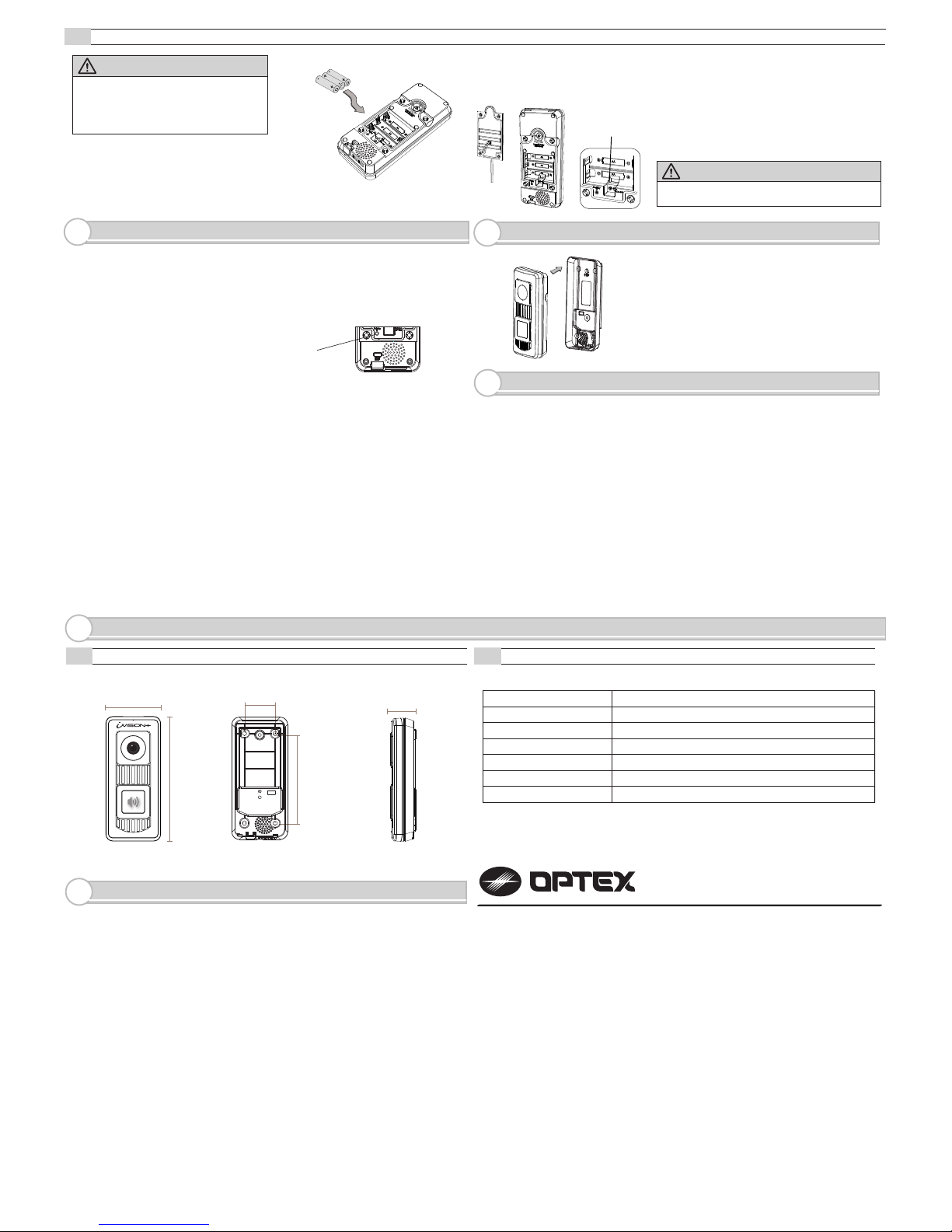
MODEL NAME: OPTEX iVISION+ (IVP-DU) Door Camera Unit
Dust/Water Protection
Operating Temperature
Camera/Lighting Unit
Battery Life Expectancy
Radiowave Frequency
WARRANTY
9.
1. This product is under a warranty for a normal usage for 18 months from the date
of manufacturing. The date of manufacturing can be identified from a LOT number
indicated on a label placed in a back of IVP-DU.
2. The warranty may not be applicable when any of following circumstances is found.
- Mechanical or electrical modification is made to the product and the good’s
appearance indicates an alterations or a significant damage.
- The product is already been diagnosed by someone other than the manufacturer.
- Product malfunction is resulting from an improper usage, an accident,
natural disaster or any environmental event.
- Please call our technical assistance before arranging a return.
PAIRING WITH IVP-HU (Handheld Monitor Unit)
5.
MOUNTING THE UNIT
6.
OPERATION CHECK
7.
SPECIFICATION
8.
4-3
Powering the Unit
WARNING
External power must not be used with batteries.
8-1
Dimensions
8-2
Specification Table
*
1
HOME ID is an unique identification number for your iVISION+ system.
Pairing Button
70mm / 2.76” 40mm / 1.57”
120mm / 4.72”
40mm / 1.57”
162mm / 6.38”
- 20 to 50 degC (-4 to 120 degF)
< 90% RH (no condensation)
IPX4 Splash Proof (Water Drain Structure)
2.4 GHz
12 month *
* Based on 3 activations (approx. 10sec each) per day
Operating Humidity
Power
Color vision / IR lighting LED
Battery (3 AA Alkaline) or AC/DC 10-24V 3W (max)
5923140
REV 1.02
OPTEX INC. (U.S.)
URL: http://www.optexamerica.com/
OPTEX DO BRASIL LTDA. (Brazil)
URL: http://www.optex.net/br/es/sec/
OPTEX (EUROPE) LTD. / EMEA HQ (U.K.)
URL: http://www.optexeurope.com/
OPTEX CO., LTD. (JAPAN)
URL: http://www.optex.net/
LOT:YYWWZ(e.g.LOT1350Z)
YYindicateslasttwodigitsoftheyearmanufactured(e.g.“13”=Year2013)
WWindicatesXthweekoftheyearmanufactured(e.g.“50”=50thweek)
 Loading...