

OPTEX IVPC-DI Installation Manua
No.59-2725-4 1910-29
SETTINGS and INSTALLATION GUIDE
EN
Introduction
This guide covers the installation and setup for the door interface unit of the IVPC system. The IVPC-DI can be used
as a chime, dry relay output, or both. Common applications are for switching power to a maglock or a door strike.
Please see the example circuits below for ideas.
General Information
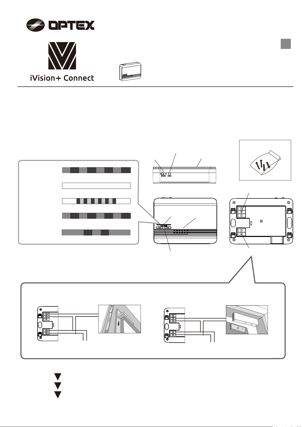
LED indications
<<
Power on
(Before pairing)
Power on
(Pairing completed)
Pairing success
[tone 1]
Pairing failure
[Beeps]
>>
Blinking (Red)
Solid light (White)
Blinking (Blue)
Blinking (Red)
Door interface
Parts indications
<<
Pairing switch
Mode switch
LED indicator
IVPC-DI
< Accessories >
>>
Screws & anchors
Mounting plate
Terminal; Relay output
Speaker
Tone/unlock
[tone 1 to 5, or mute]
Relay output wiring examples
<<
N.O.
COM
Power supply
What to expect
1
Mounting and wiring;
2
Pairing;
3
Operation check;
Blink once (Red)
Volume +/- button
(mute and 3 steps)
- During volume adjustment, the default type of
tone sounds regardless the selected type of tone.
>>
Door Strike
mount the IVPC-DI, connect power wires and signal wires to external devices.
pair the IVPC-DI to the IVPC-DS, using the IVPC-MS or using the OPTEX Vision App.
test the performance of the IVPC-DI and external devices of the system.
- A confirmation beep sounds when the unit is muted.
COM
N.C.
Power supply
Terminal; Power input
Magnetic Lock
- 1 -
1
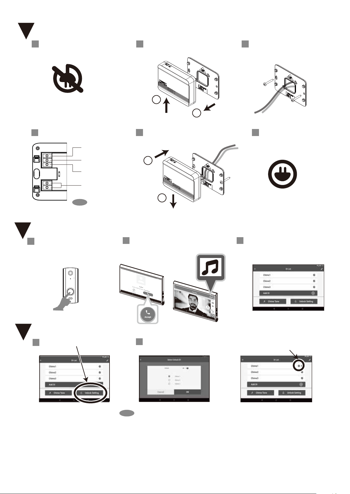
Mounting and wiring
1 Turn off all equipment including
the external devices of the system.
OFF
4
Wire to the terminals.
N.O. (ex. Strike)
COM
N.C. (ex. Maglock)
Power
10 to 24 V AC/DC
NOTE
Polarity is not a concern.
2
Remove the main unit
from the mounting plate.
1
2
Slide up.
5
Mount the main unit on the mounting plate.
Attach
1
2
Slide down.
Pull off.
3
Pass the wires through and fix
the mounting plate to the wall.
6
Turn on all equipment.
ON
2
Pairing
1
Press the doorbell on IVPC-DS to
be paired with the IVPC-DI.
3
Unlock setting
Press the “Unlock Setting” button.
1
After accepting the call, press the icon
2
shown below to start the wizard for
the IVPC-DI.
2
Select which chime will also
function as a door release.
Confirm the correct number of paired
3
chimes is shown at the completion of
the wizard.
“Unlock” marking is indicated
on the assigned IVPC-DI.
NOTE
-
One IVPC-DS can pair up to four IVPC-DI. However, only one IVPC-DI can be assigned to
operate its relay. The other three are limited to sounding their chimes.
- For example, one IVPC-DI operates the door-lock at the front while a second IVPC-DI serves
as a chime in a back room.
- The chimes sound simultaneously with the same type of tone.
- 2 -
 Loading...