

Page 1

Avoid using the Handheld Monitor Unit in the following areas
- Close to a fire, thermal appliance or other source of extreme heat/cold.
- Within 10ft (3m) of a television, microwave oven, personal computer, wireless
LAN equipment, wireless audio/visual equipment - the radio frequency waves
emitted by these devices can affect operation.
- In direct sunlight.
- Where extreme fluctuations in temperature can occur - if moving the unit from
a warm to cold environment, or vice versa, please allow 30 minutes before use.
IVP-HU features
2.4 inch TFT LCD Monitor
Wall-mountable Cradle
Max 4 Units in a System
micro-USB port to PC connection
Manual/Auto Talk Switching
IVP-HU
(Handheld Monitor Unit)
Installation Instructions
ATTENTION:
Thank you for purchasing the iVISION+ wireless video intercom.
Before installation and usage, please read this instruction manual thoroughly
and keep this safe for future reference.
Wireless Video Intercom
IMPORTANT NOTICE
1.
Privacy & portrait/image rights
- Please respect the privacy and image rights of others when using this
equipment. By using this equipment the user assumes total responsibility in
upholding these rights.
- Images stored must not be used for any purpose other than that for which the
equipment is designed.
- Images should be deleted once no longer required.
Operations under harsh environments such as out of warranted temperature,
rapid temperature change, high humidity, constant moisturization may cause the
unit to malfunction.
Electronic device such as TVs, Radios, PCs, Microwave ovens or any other device
with an electric motor may cause the unit to malfunction.
Impact or shocks can cause severe damage to the unit. Please handle the unit
with care and operate without exerting strong forces.
Transmission range of communication between units may decrease under
the following conditions.
- Any unit is installed on a metal surface.
- Presence of reinforced concrete, steel doors or other metal construction
materials between units.
- Places near strong radio sources such as broadcast stations or substations.
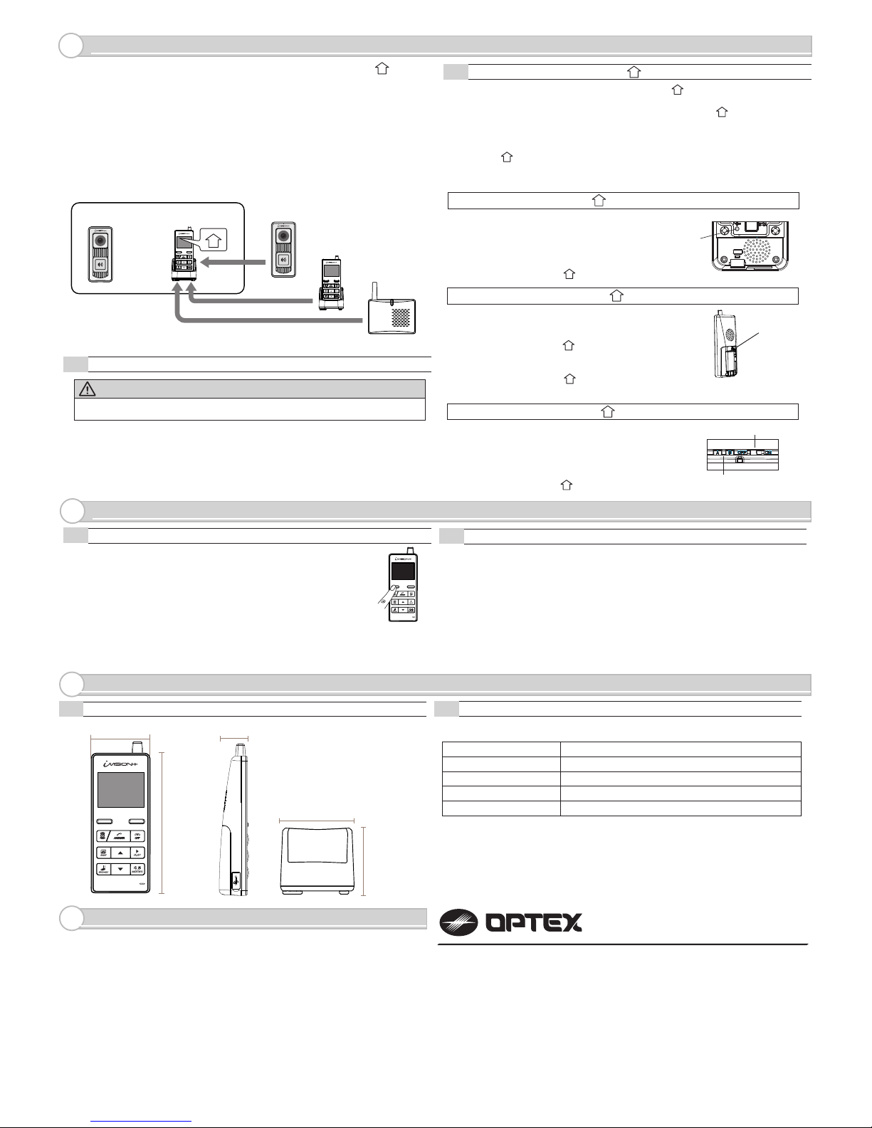
PARTS IDENTIFICATION
2.
CHOOSING LOCATION
3.
INSTALLATION
4.
POWERING THE UNIT
5.
The performance of the iVISION+ system is dependent on the radio frequency
environment and distances between devices. Following materials may decrease
the maximum transmission distance and may cause the Handheld Monitor Unit
inability to respond to incoming signals.
• Metal barricades such as ,metal doors and shutters.
• Walls with aluminium foil insulation.
• Concrete or galvanized metal walls.
The effective communication range is around 300ft (100m) in an open air condition
(line of sight). This range will be significantly reduced by the number and thickness
of walls through which the signal is required to pass. Please keep to a minimum
number of walls wherever possible.
Handheld Monitor Units use 2.4GHz radio frequency. Any electrical appliance may
become a potential cause for malfunction. Please avoid using the Handheld Monitor
Unit near microwave oven or any electrical devices with similar radio frequency.
CAUTION
Please use the includedbattery pack and a power adaptor only.
Do not disassemble or attempt to use alternative battery packs.
Handheld Monitor Unit must be set on Charging Cradle to retain its power while
iVISION+ system is not in operation. The Charging Cradle can either be free-standing
on a horizontal surface or be mounted on a wall as described below.
Charging Cradle
Mounting Screw
Handheld Monitor Unit
AC Adaptor
Battery Pack
1. Connect Battery pack
to the main unit.
LCD display
LEFT function key
“OPEN DOOR”
“SNAP”
“BROWSE”
Scroll buttons
( UP/ DOWN)
Microphone
“BRIGHTNESS”
“PLAY”
“OFF”
“ANSWER”
RIGHT function key
2. Connect AC adapter
to Charging Cradle
3. Press and hold “OFF”
button to power on.
Set the unit onto
the cradle for charging.
Remove and keep the battery seperately if the device is not used
for more than a month. It may require several charge-discharge process
before a battery regains its full capacity after a long storage period.
Battery Pack Compartment
Speaker
USB connection port
Battery Cover
Pairing button
Page 2
WARRANTY
9.
SPECIFICATION
8.
OPERATION CHECK
7.
PAIRING WITH OTHER iVISION+ DEVICES
6.
MODEL NAME: OPTEX iVISION+ (IVP-HU) Handheld Monitor Unit
8-1
Dimensions
8-2
Specification Table
(1) In a normal operation mode, press and hold the left function key
for two seconds to enter menu mode.
(2) Select menu number 3 # DEVICES IN NETWORK
by up and down key.
(3) Press LEFT function key to “OK”
(4) The display will show the number of iVISION+ devices in the network.
Confirm number of iVISION+ devices registered with the HOME ID.
(5) Maximum numbers of devices in an iVISION+ system are;
2 IVP-DU, 2 IVP-GU and 4 IVP-HU. Go over pairing procedure unless optimal
numbers of devices are displayed.
One Handheld Monitor Unit (IVP-HU) must be configured to have a HOME ID*1
prior to paring up with other iVISION+ devices.
*1 HOME ID is an unique network identification protocol for iVISION+ system.
One Handheld Monitor Unit can issue the HOME ID and all other devices on
the same system must be assigned the same HOME ID.
WARNING
Any pre-existing HOME ID set up will be cleared out with this procedure.
6-1
How to create HOME ID by a Handheld Monitor Unit
If not purchased in a bundle package, IVP-DU is
in the pairing mode when powered up. IVP-DU
beeps continuously when PUSH button is pressed.
To purposely enter into a paring mode, press PUSH
button once and hold a pairing button in a back.
Once IVP-DU is paired, HU shows “DU# CONNECTED”.
(1) Press “OFF” and then press pairing button in the back of the unit once.
The IVP-HU will be in a pairing mode.
(2) Press the pairing button again and hold until the unit makes a beep sound.
(3) Press “Left function key” on the front to confirm “CREATE.”
Pairing button
7-1
Confirming number of iVISION+ devices in a HOME ID
7-2
Checking operations on Handheld Monitor Unit
(1) Make sure IVP-HU has been charged and there is a green indication on the top
of display.
(2) To confirm RF reception, bring IVP-HU and IVP-DU in a line of sight.
(3) Press “Push button” on a paired Door Camera Unit.
All paired IVP-HUs display an image from the IVP-DU.
(4) Press “Answer” on any of the IVP-HU.
Voice from IVP-HU will be heard from the IVP-DU.
(5) Press “OFF” on the IVP-HU to terminate the communication.
(6) Move IVP-HU (and IVP-DU) to a desired location and repeat (3) to (5)
to confirm reception of signals.
80mm / 3.15”
71mm / 2.8”
Operating Temperature
Dust/Water Protection
Radiowave Frequency
0 to 40 degC (32 to 104 degF)
< 90% RH (no condensation)
N/A (Indoor Use Only)
2.4 GHz
Operating Humidity
Power
Power Adaptor 5.5V DC
Pairing Button
60mm / 2.36”
30mm / 1.18”
145mm / 5.71”
SYSTEM SETUP
1 DATE & TIME
2 SYSTEM CONFIGURATION
3 DEVICES IN NETWORK
4 PC CONNECTION
OK
BACK
Pairing button A& B
Sound ON/OFF Switch
Use designated battery, IVP-BAT, for IVP-HU.
Please contact your regional technical support for procurement information.
5921603
REV1.03
OPTEX INC. (U.S.)
URL: http://www.optexamerica.com/
OPTEX DO BRASIL LTDA. (Brazil)
URL: http://www.optex.net/br/es/sec/
OPTEX (EUROPE) LTD. / EMEA HQ (U.K.)
URL: http://www.optexeurope.com/
OPTEX CO., LTD. (JAPAN)
URL: http://www.optex.net/
1. This product is under a warranty for a normal usage for 18 months from the date
of manufacturing. The date of manufacturing can be identified from a LOT number
indicated on a label placed in battery compartment of IVP-HU.
2. The warranty may not be applicable when any of following circumstances is found.
- Mechanical or electrical modification is made to the product and the good’s
appearance indicates an alterations or a significant damage.
- The product is already been diagnosed by someone other than the manufacturer.
- Product malfunction is resulting from an improper usage, an accident,
natural disaster or any environmental event.
- Please call our technical assistance before arranging a return.
LOT:YYWWZ(e.g.LOT1350Z)
YYindicateslasttwodigitsoftheyearmanufactured(e.g.“13”=Year2013)
WWindicatesXthweekoftheyearmanufactured(e.g.“50”=50thweek)
NOTE: An additional Device DU, HU and GU must be paired to HU only:
1
6-2
Handheld Monitor Unit bundled with Door Camera Unit already has a HOME ID
set and paired to each other.
IVP-DU IVP-HU
IVP-DU
IVP-HU
IVP-GU
Exsiting
iVISION+
System
1
How to enroll HU, DU and GU to HU
1
(1) Press pairing button twice in the back of IVP-HU .
The unit will be in “PAIRING MODE”.
(2) Proceed to “SCAN” by pressing “Left function key”. IVP-HU starts scanning
for other devices for 60 seconds.
(3) Prepare other iVISION+ device into their pairing mode. (REF as follows)
When the device is ready, the new unit will be enrolled to the HOME ID and
IVP-HU shows which device was connected.
(4) If another device needs to be enrolled, re-enter “SCAN” by “Left Function key”
and repeat the process.
1
1
1
IVP-DU: Door Camera Unit to HU
1
IVP-HU: Handheld Monitor Unit to HU
1
IVP-GU: Gateway Chime Unit to HU
1
1
If not purchased in a bundle package, by the factory
default, IVP-GU is in the pairing mode when powered up.
IVP-GU beeps continuously and green/red LED blinks.
Press down both A and B buttons while powering up
the Gateway Chime Unit to enter the pairing mode.
Once IVP-GU is paired, HU shows “GW CONNECTED”.
1
If not purchased in a bundle package, IVP-HU is in the
pairing mode when powered up. Choose “JOIN” by
“Right function key” to enroll into an existing HOME ID.
Once IVP-HU is paired, HU shows “HU# CONNECTED”.
If otherwise, follow the instruction 6-1 to create
a new HOME ID. After an enrollment of new HU,
reset a Time & Date on HU to reflect the setting
onto the added HU unit.
1
1
 Loading...