

Page 1
No.59-2736-2 1903-06
SETTINGS and INSTALLATION GUIDE
EN
Introduction
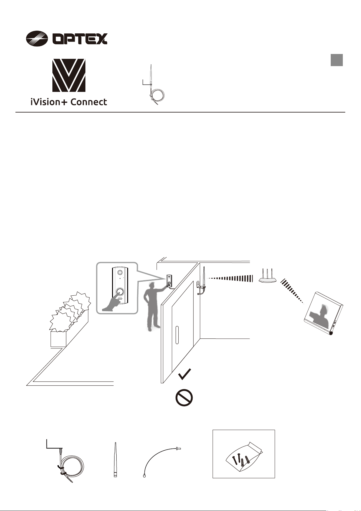
This guide covers the installation of the external antenna optional accessory for the IVPC-DS.
The external antenna comes with a 5 feet cable to allow for greater flexibility in antenna placement.
The guide will cover some key considerations for optimal placement of the antenna.
General Information
The IVPC-ANT helps by providing an antenna at a position that avoids obstacles against radio waves such as
walls and doors. The best communication is achieved by a direct open path between the communicating devices,
in this case the Wi-Fi router and the IVPC-DS. The antenna will not boost signal strength. If the Wi-Fi signal is too
weak at the IVPC-DS location, please consider getting a Wi-Fi range extender.
External antenna
for Wi-Fi communication only.
(Sub 1 GHz IVPC-DI range will not be affected.)
IVPC-ANT
Parts identifications
Bracket and cable
l = 1.5 m (5 ft.)
Antenna
Connecting cable
l = 0.2 m (7.9 inch)
♬
Refer to the Settings and Installation Guide for the IVPC-DS.
Do not use any external antenna other than the IVPC-ANT.
Do not extend the antenna and connecting cables.
(The cable and antenna are matched for optimal performance.)
< Accessories >
Screws & anchors
- 1 -
Page 2

What to expect
1
2
3
4
1
Important points to consider
1. Activate the IVPC-DS and check the signal strength indicator using the IVPC-MS
or a device running the OPTEX Vision App. This will be your reference level.
2. The IVPC-DS can be unmounted and brought to the intended antenna install
location for Wi-Fi range checking before attaching the antenna. This is useful
for assessing your Wi-Fi environment.
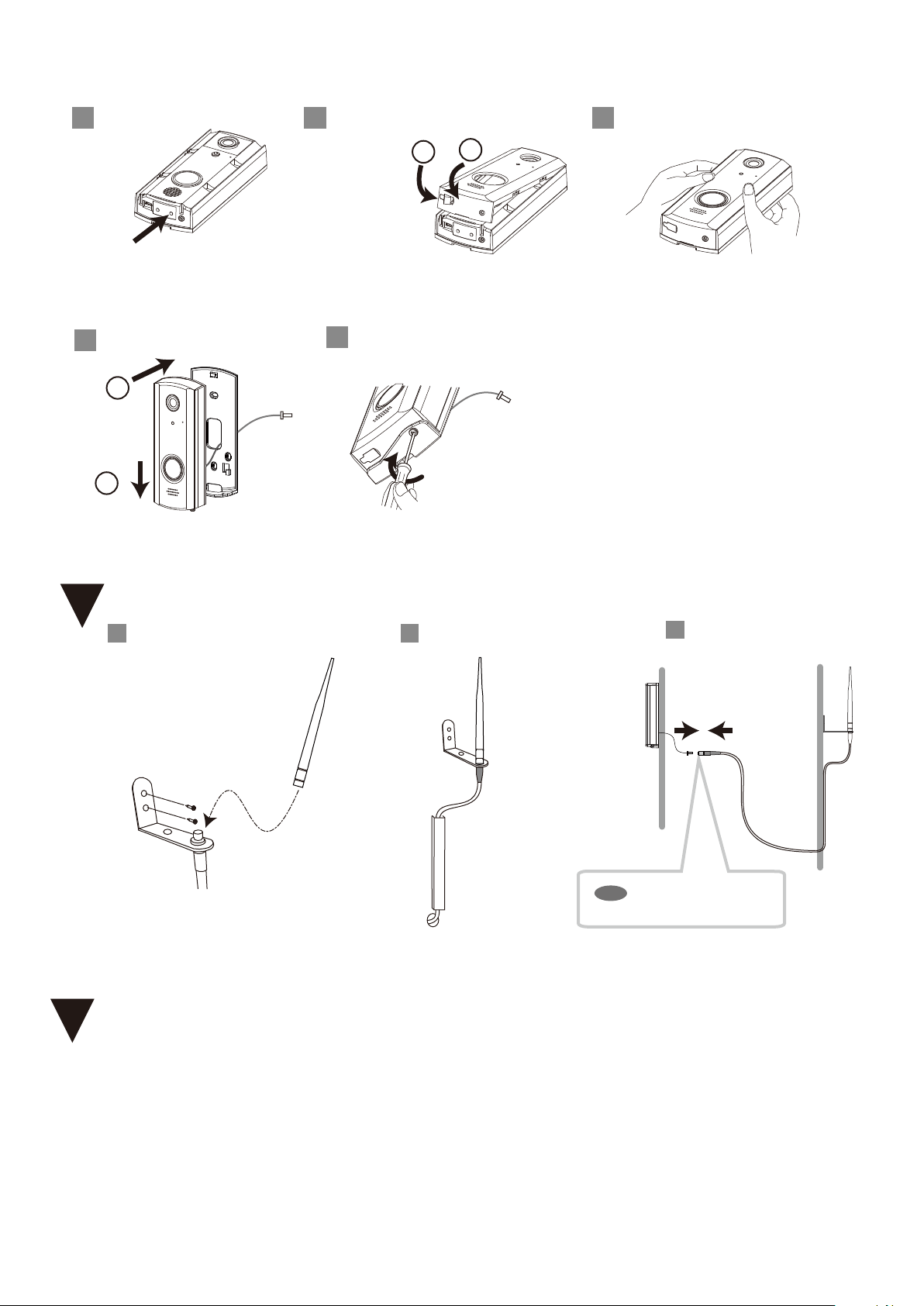
Preparation on the IVPC-DS
2
Important points to consider;
Preparation on the IVPC-DS;
Mounting;
Confirm operation;
how to mount the IVPC-ANT.
make sure everything is working.
read to avoid multiple installation attempts.
steps to take before mounting.
Loosen the lock screw.
1
4 Power off.
Push the power on/off button.
Confirm LED is off.
6 7 8
Switch from INT to EXT of the
internal/external antenna switch.
Remove the main unit.
2 3
2
Pull off the
main unit.
Slide the
1
main unit.
5
! Caution
- If hardwired, please turn off
power to the device while
the terminals are exposed.
Attach the connecting cable.
Remove the
rubber bushing.
Remove the back cover.
Remove the front cover.
Lift up.
1
2
Insert a flat driver bit to pry open.
Replace the back cover.
EXT
EXT
! Caution
- The back cover protects against
water intrusion. Make sure nothing
is interfering with it.
- 2 -
Page 3
9 10 11
Power on.
Replace the front cover. Push the front cover to secure.
1
2
Replace the
rubber bushing.
Push.
1
Push the power on/off button.
12
Mount the main unit.
1
Attach the
main unit.
2
Slide down.
Mounting
3
1
Mount the bracket and set the antenna.
If having trouble with the cover, make sure
the bushing is not in the way.
Tighten the lock screw.
13
2
Run the cables.
Connect cables.
3
4
Confirm operation
- Do a test run to check whether the signal strength is enough.
- Push the doorbell button on the IVPC-DS and confirm audio and video
on the IVPC-MS or the OPTEX Vision App.
- Hand this guide and the user manual to the end user for safekeeping.
- 3 -
NOTE
Consider waterproof
treatment as necessary.
Page 4

Troubleshooting
<<
>>
Status Check point
The signal has not
improved.
The Wi-Fi signal is
intermittent.
Check that the internal/external antenna switch is
properly set to EXT.
Check that the antenna is properly connected to the
back of the IVPC-DS port
Check if other devices are showing Wi-Fi issues.
Check if something has changed in the environment
to interfere with the signal.
NOTE Test the total operation after the installation completed.
Solution
Switch to EXT of the
Attach the connecting cable of the IVPC-ANT so it is firmly on the port.
Check for Wi-Fi coverage using the IVPC-DS, IVPC-MS or device running
the OPTEX Vision App.
Move the Wi-Fi router closer to the IVPC-DS or use a range extender.
Dispose of used products should be in accordance with local government
regulations/laws.
internal/external antenna switch
of the IVPC-DS.
OPTEX CO., LTD. (JAPAN)
URL: www.optex.net
OPTEX INC. (U.S.)
URL: www.optexamerica.com
p. 800-966-7839
warranty-returns@optexamerica.com
tech@optexamerica.com
- 4 -
ivisionplusconnect.info/techtips
Copyri ght (C) 2019 OPTEX C O.,LTD.
 Loading...