

Page 1
High Mount
High Mount
Outdoor Detector
Outdoor Detector
HX -40RAM
HX -40RAM
By utilizing the OPTEX’s unique pyro-element,
HX series achieves high reliable detection
performance against false and missed alarms.
HX series provides stable and accurate
detection in outdoor severe environmental
conditions.
HX-40RAM: Battery operated model with IR
anti-masking feature.
Installation and connection methods differ
depending on the type and size of the
transmitter battery.
INTRODUCTION
1
No.59-1547-1
INSTALLATION MANUAL
N219
CONTENTS
1
INTRODUCTION
1-1 BEFORE YOUR OPERATION 1
1-2 PARTS IDENTIFICATION 2
1-3 DETECTION AREA 2
2
PREPARATIONS
2-1 TRANSMITTER PREPARATION 3
2-2 BATTERY PREPARATION 4
3
INSTALLATION
3-1
DETERMING THE DETECTION LENGTH
3-2 MOUNTING THE BATTERY 5
3-3 MOUNTING THE TRANSMITTER
AND THE BATTERY BOX 7
3-4 MOUNTING THE BRACKET 8
3-5 ADJUSTING THE VERTICAL ANGLE 9
3-6 WIRING 10
4
SETTING
4-1 FUNCTION 11
4-2 ANTI-MASKING 13
4-3 AREA ADJUSTMENT 14
5
SPECIFICATIONS
5-1 SPECIFICATIONS 15
5-2 DIMENSIONS 16
5
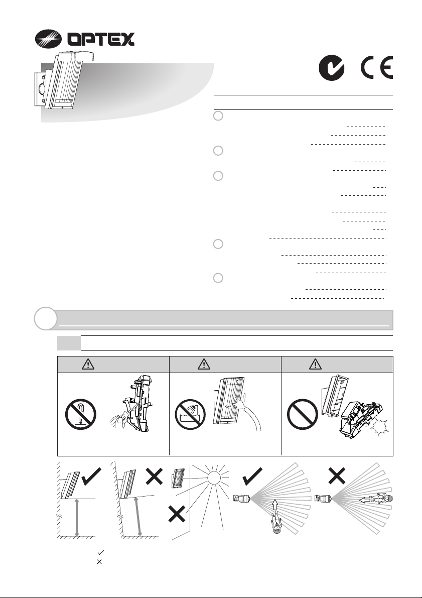
BEFORE YOUR OPERATION
1-1
Warning Warning Caution
Do not repair or modify
product
Parallel
2.5 - 3.0 m
(8.3 - 10 ft.)
The check ( ) mark indicates recommendation.
The cross ( ) mark indicates prohibition.
Tilt
Keep the product away from
the water
-1-
Mount the unit securely
Page 2
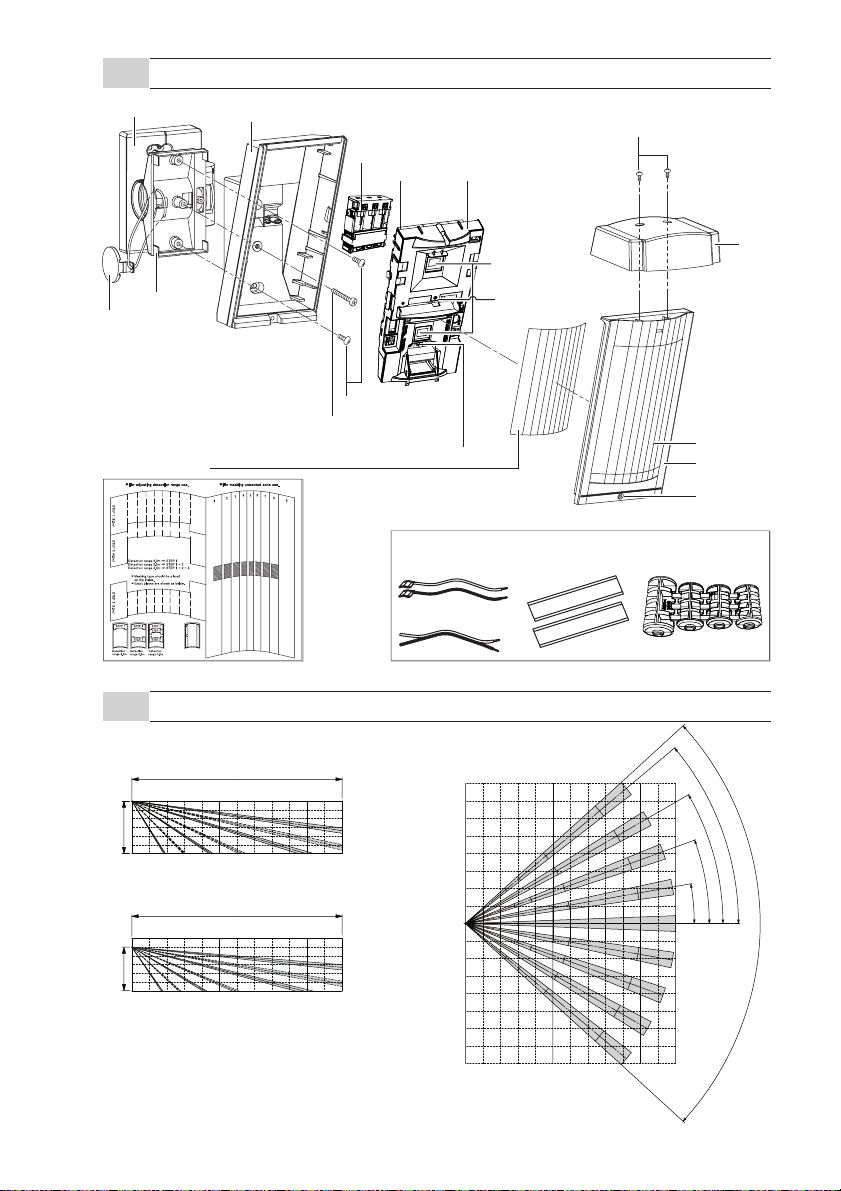
PARTS IDENTIFICATION
1-2
Bracket base
Base
Screw (3×10 mm)
Battery box
Main unitTerminals
Bracket
Shaft cover
Area masking seal
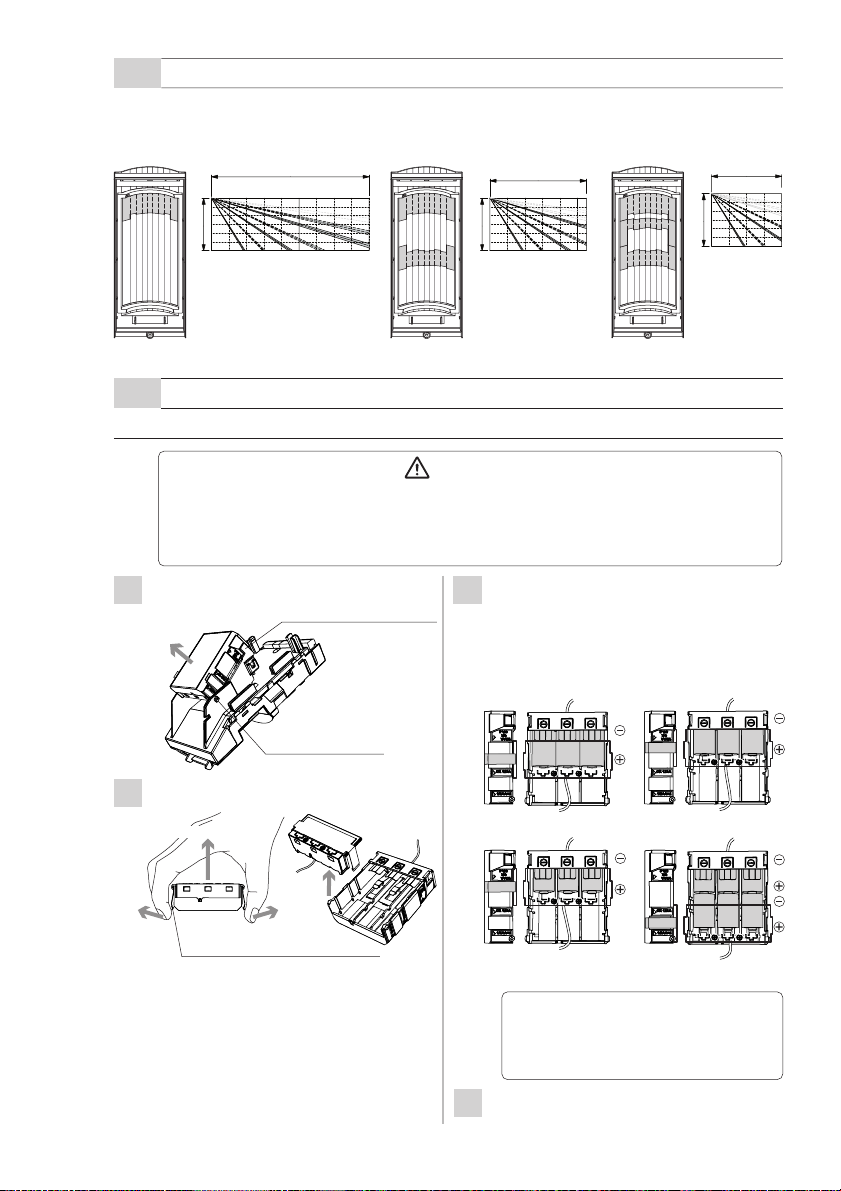
DETECTION AREA
1-3
Side view
(Installation height 3.0 m (10 ft.) )
12 m (40 ft.)
Screw (4×20 mm)
Lock screw (M4×35 mm)
Accessories
Battery leads
Alarm cable
Top view
8 m
(26.7ft.)
PIR sensor
(Don not touch)
Anti-masking infrared LED
LED indicator
Velcro tapes
Hood
Lens
Cover
Lock screw
Dummy battery
3.0 m (10 ft.)
(Installation height 2.5 m (8.3 ft.) )
2.5 m (8.3 ft.)
• vertical angle : 2.5 degrees (1 click) upward
(Refer to “caution” in 3-5).
12 m (40 ft.)
-2-
8 m
(26.7ft.)
40°
30°
20°
12 m
(40 ft.)
10°
85°
0
Page 3
Note : How to change detection length>>
Apply area masking seal to limit the detection length. Note that there are three
different types of seal.
9.0 m (30 ft.)
5.5 m (18.3 ft.)
4.0 m (13.3 ft.)
1
3
2
3.0 m (10 ft.)
3.0 m (10 ft.)
PREPARATIONS
2
11
2
3.0 m (10 ft.)
To use HX-40RAM, transmitter and battery should be prepared.
First check the following flowchart.
• transmitter size • battery type
Is it possible to
accommodate the
transmitter in the space
between Base and Main
unit (refer to 2-1)?
No
Change the transmitter.
TRANSMITTER PREPARATION
2-1
Yes Yes
Is the battery in the transmitter
CR123, CR2, or 1/2AA?
• battery preparation • Reference
It is possible to share the
batteries of HX-40RAM.
Prepare the required batteries
which are the same type as
used in the transmitter.
It is not possible to share the
No
batteries of HX-40RAM.
Prepare the required batteries
for HX-40RAM.
The transmitter that HX-40RAM can accommodate are either 1 or 2 below:
Note that a transmitter with greater dimensions than these is not applicable.
Installation position for the transmitter and the battery box differ depending on their dimensions.
Case 1) 122 × 50 × 33 mm
Case 2) 80 × 50 × 22 mm
22
Refer to
“Battery
Sharing
Possible
case” in 2-2.
Refer to
“Battery
Sharing
Impossible
case” in 2-2.
122
Battery box
Transmitter
33
140
80
Transmitter
Battery box
15
-3-
Page 4
BATTERY PREPARATION
2-2
-Battery Sharing Possible Case
Power supply is available from the battery box to both HX-40RAM and the transmitter.
Transmitter
HX-40RAM Battery box
Note that the battery type shall be the same as
that used for the transmitter.
Type CR123A CR2 1/2AA
Dummy battery
POWER
ALARM
OUTPUT
HX-40-RAM Main unit
POWER
INPUT
Voltage
Number of
cells to use
*1: 3.6 VDC 1/2 AA battery in series.
3.0VDC 3.0VDC 3.6VDC
3 cells 3 cells 3 cells
(See P5)
1/2AA(*1)
7.2VDC(*1)
6 cells(*1)
-Battery Sharing Impossible Case
Separate batteries for HX-40RAM and the transmitter.
Transmitter
TROUBLE
OUTPUT
INSTALLATION
3
ALARM
HX-40RAM Main unit
HX-40RAM Battery box
Not
used
POWER
POWER
OUTPUT
INPUT
-Installation procedure
DETERMING THE DETECTION LENGTH
MOUNTING THE BATTERY
-Battery Sharing Possible Case
-Battery Sharing Impossible Case
MOUNTING THE TRANSMITTER
AND THE BATTERY BOX
Type CR123A
Voltage
Number of
cells to use
If CR123A battery cells are unavailable, three CR2
battery cells (3.0 VDC) can be substituted.
Do not use 1/2AA batteries.
*
Do not use the attached dummy batteries or battery
lead.
3.0VDC
3 cells
(See P6)
MOUNTING THE BRACKET
ADJUSTING THE VERTICAL ANGLE
-4-
Page 5
DETERMING THE DETECTION LENGTH
3-1
Apply masking seal to set the detection length directly on lens. To set an length shorter than
the standard 12 meters, select one of the three patterns and apply the appropriate masking
seal to the lens.
9.0 m (30 ft.)
5.5 m (18.3 ft.)
4.0 m (13.3 ft.)
1
3
2
3.0 m (10 ft.)
MOUNTING THE BATTERY
3-2
-Battery Sharing Possible Case
11
2
3.0 m (10 ft.)
Warning
Do not use batteries of different capacities (i.e.: mixing new and used batteries) or of
different manufacturers and/or types together. Not observing the above may result in
an explosion, leakage of electrolyte, emission of toxic gases or other outcomes that
may be harmful to people and property.
Remove the battery box from the main
1
unit.
Pull
Remove the battery box cover.
2
Lift and remove
Open the claws (at 2 places).
Disengage the bosses
(at 2 places).
Mount batteries and put the cover onto
3
the right position indicated on the side of
the battery box.
Hook the cover firmly by the claws on the
right and left sides.
CR123A×3 (3.0VDC) CR2×3 (3.0VDC)
×3 (3.6VDC) 1/2AA×6 (7.2VDC×3) (*1)
1/2AA
3.0 m (10 ft.)
Open the claws (at 2 places) slightly.
-5-
*1: 3.6 VDC 1/2 AA
battery in series.
Caution>>
Do not contact the ends of the red
and black wires to avoid shortcircuit.
Open the transmitter cover and remove
4
the battery.
Page 6

Place the battery lead (included in the
5
set) and a dummy battery in the battery
case of transmitter.
CR123A
CR2
1/2AA
1/2AA
Dummy battery
* Twist and cut off the portion that fits the applicable
battery type.
BATTERY LEAD(red)
BATTERY LEAD(black)
Connect the alarm cable to the
6
transmitter and close the cover.
Transmitter
Put the alarm wire outside
through the wiring hole
Alarm cable
Dummy battery
-Battery Sharing Impossible Case
Arrange 3 cells each of CR-123A (recommended) or CR2.
Warning
Do not use batteries of different capacities (i.e.: mixing new and used batteries) or of
different manufacturers and/or types together. Not observing the above may result in
an explosion, leakage of electrolyte, emission of toxic gases or other outcomes that
may be harmful to people and property.
Remove the battery box from the main
1
unit.
Pull
Remove the battery box cover.
2
Lift and remove
Open the claws (at 2 places) slightly.
Open the claws (at 2 places).
Disengage the bosses
(at 2 places).
After installing the batteries, check the
3
guide on the side and install the cover.
Hook the cover firmly by the claws on the
right and left sides.
CR123A CR2
Caution>>
Do not contact the ends of the red
and black wires to avoid shortcircuit.
Connect the alarm cable to the
4
transmitter and close the cover.
Transmitter
Alarm cable
Put the alarm wire outside
through the wiring hole
-6-
Page 7

MOUNTING THE TRANSMITTER AND THE BATTERY BOX
3-3
Using a Velcro tape (included in the set),
1
fix the transmitter to the main unit.
Fix the base to the wall surface.
4
Example of Case 1
Connect the alarm cable to the terminal
2
block of the main unit.
Install the battery box into the main unit
3
and connect the necessary wires to the
(See 2-1) (See 2-1)
Velcro tape
Example of Case 2
Velcro tape
terminal block. (refer to “3-6 Wiring”)
Example of Case 1
Engage
3
the claws
(at 2 places).
Insert and
secure here.
2
Example of Case 2
Insert and
secure here.
2
Engage
3
the claws
(at 2 places).
Mount the main unit and the lens onto
5
the base.
Place the main unit Put the cover on
1 2
3
Tighten the locking screws.
1
Engage
the bosses
(at 2 places)
Caution>>
1
Engage
the bosses
(at 2 places)
Fix the battery leads and
alarm cable through the
grooves as shown in the
diagram.
Cut off the excessive
portion of wiring to the
necessary length.
Protruding wires, if any,
may be caught by the
base.
-7-
Caution>>
If the main unit does not easily fit on
to the base, the transmitter may be in
contact or the wiring may have
become caught.
Page 8

MOUNTING THE BRACKET
3-4
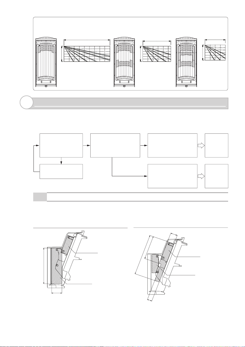
Using the bracket makes it possible to adjust the unit horizontally by ± 90 degrees.
In cases where the ground is uneven and therefore not parallel with the base of the unit, it is
possible to adjust the unit vertically by ± 20 degree (refer to 3-5)
Caution>>
Do not change the detection
length with bracket.
Use the masking seal to
adjust the detection length.
90°
-Bracket installation
Remove the up-down lock screw.
1
Push the shaft cover clip outwards to
2
remove the shaft cover.
Shaft cover
Press with suitable tool.
e.g. small screwdriver
90°
20°
20°
Fasten the bracket to the wall.
4
Change the bracket direction according
to whether the Main unit is to face left
or right.
Open the up-down lock screw knockout
5
for bracket.
Loosen the adjustment screw two turns.
3
Adjustment screw
Caution>>
Do not loosen the
screw too much.
The screw separates
from the unit.
-8-
Page 9

Install the base on the bracket.
6
Caution>>
Do not tighten the up-down lock
screw.
ADJUSTING THE VERTICAL ANGLE
3-5
To have the right performance, set the vertical angle parallel to a ground.
Decide the wanted detection length at first. If you choose 9.0m/5.5m/4.0m, mask the
unwanted lens with masking seals. Refer to the 3-1 for the details.
Carry out the walk test to check if the vertical
angle is perpendicular or not.
Decide the horizontal angle, and tighten
7
the adjustment screw clockwise.
Adjustment
screw
Install the Main unit and cover on the
8
base.
Complete the 3-5 “ADJUSTING THE
9
VERTICAL ANGLE”.
Remove the cover and the Main unit to
10
tighten the up-down lock screw, and
install the Main unit and cover on the
base again.
Fit the shaft cover into the place.
11
12 m (40 ft.)
3.0 m (10 ft.)
If you see the detection only
inside the designated distance,
change the vertical angle upward.
* This is the case to have 12 meters detection length.
If you see the
detection at the
designated distance,
no adjustment is
needed.
If you see the detection outside
the designated distance, change
the vertical angle downward.
Caution>>
If the base of the unit is already parallel to the ground,
• Do not change the detection distance by tilting the unit up or down. Detection area and
length should be adjusted with masking tapes. Refer to 1-3 and 3-1 for the details.
• Walk test the unit to ensure that the desired detection distance is achieved.
0°
5° (2 clicks)
0° is the right setting for 3m (10 ft.)
height installation.
Adjust 1 click (2.5° upward) for 2.5m
(8.3 ft.) height installation to maintain
the 12m (40 ft.) detection range.
NOTE: This setting is available only for the HX is installed vertically to the ground.
10° (4 clicks)
-9-
Page 10

WIRING
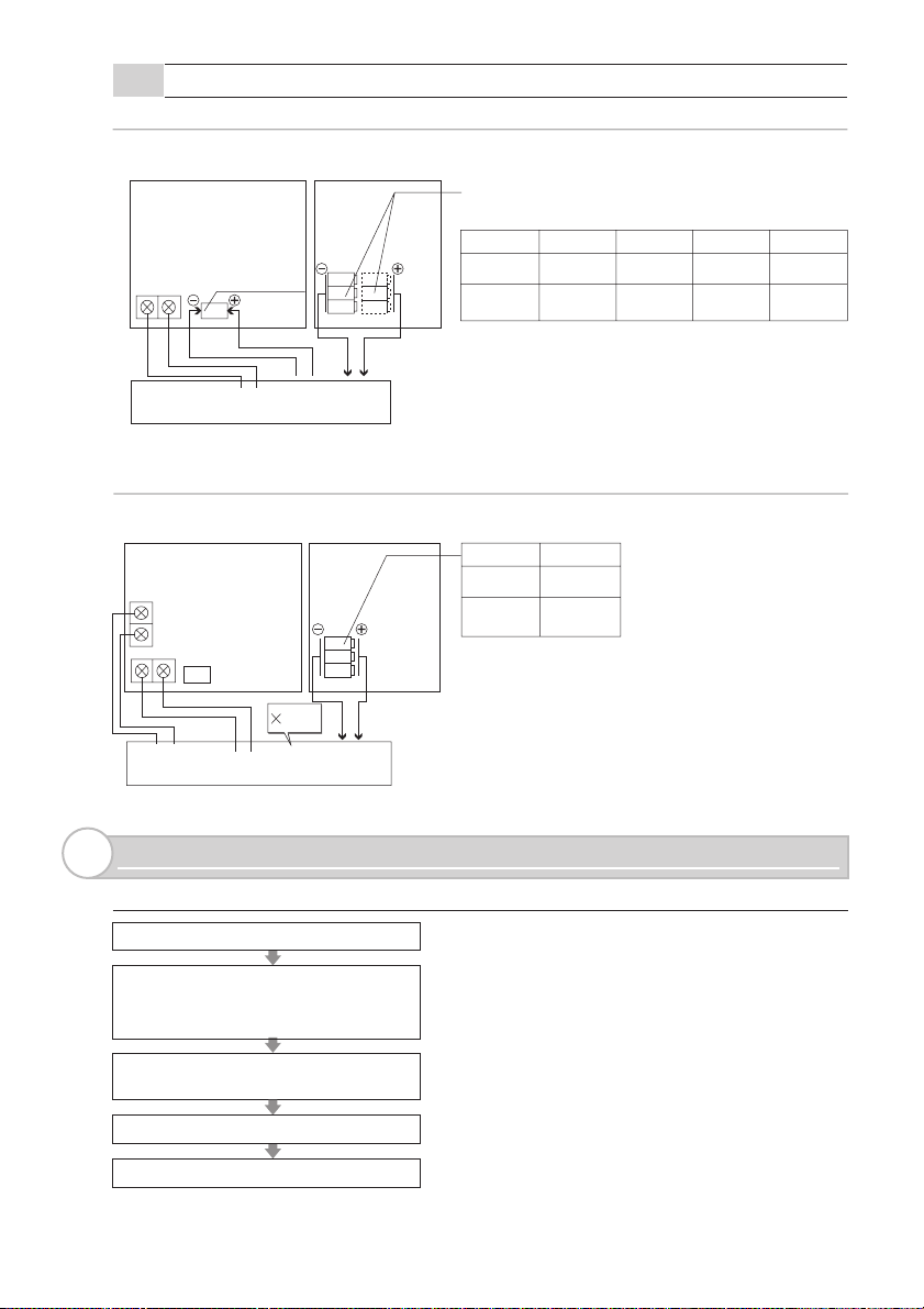
3-6
T
A
M
P
E
R
T
R
O
U
B
LE
A
L
A
R
M
P
O
W
E
R
O
U
T
P
O
W
E
R
N
O
C
O
M
N
C
N
IN
C
N
O
S
P
N
O
C
O
M
N
C
+
+
-
-
*1: TAMPER terminals to be connected to a 24 hour supervisory loop.
-Battery Sharing Possible Case
TAMPER OUTPUT (N.O.) *1
TAMPER
NO
COM NC
TAMPER OUTPUT (COM) *1
TAMPER OUTPUT (N.C.) *1
TROUBLE OUTPUT
TROUBL
OUT (T.O.)
ALARM OUTPUT (N.O.)
SPARE (Non short)
ALARM
COM
ALARM OUTPUT (COM)
NC
TROUBLE OUTPUT
E
SP NO
Transmitter
Dummy battery
ALARM OUTPUT (N.C.)
POWER OUTPUT (–) (3 - 7.2VDC)
POWER OUTPUT (+) (3 - 7.2VDC)
POWER O
UT
POWER I
+
-
-
HX-40RAM Battery box
POWER INPUT (–) (3 - 7.2VDC)
POWER INPUT (+) (3 - 7.2VDC)
N
+
-Battery Sharing Impossible Case
• Use a transmitter with 2 inputs or low battery
terminal and connect to TROUBLE OUTPUT.
• Use 2 small transmitter units and connect one
unit to the alarm wiring and the other to the
trouble wiring (the size of such transmitters
should be small enough to be accommodated
in the HX-40RAM internal spaces (A/B)).
• To output LOW BATTERY SIGNAL to ALARM
OUTPUT terminal, set DIP-SW 5 (see p12)
“Trouble output” to “ Trouble output + Alarm”.
-10-
ALARM
TAMPER
COM NC
TROUBLE
OUT (T.O.) SP NO
NO
ALARM
COM
NC
OUTPUT
POWER OUT
-
INPUT
POWER IN
+
+
-
POWER
POWER
HX-40RAM Main unit
Transmitter
TROUBLE
OUTPUT
TAMPER
COM NC
TROUBLE
OUT (T.O.) SP NO
NO
HX-40RAM Battery box
Not
used
POWER
ALARM
OUTPUT
ALARM
NC
COM
POWER OUT
-
POWER
INPUT
POWER IN
+
-
+
HX-40RAM Main unit
Page 11

SETTING
4
FUNCTION
4-1
Dip SW
1 WALK TEST MODE
2 BATTERY SAVING TIMER
3 IMMUNITY
4 TROUBLE OUTPUT TYPE
5 TROUBLE OUTPUT TERMINAL
6 LED ON/OFF
PIR SENSITIVITY
-WALK TEST MODE
NORM.
-BATTERY SAVING TIMER
120s
TEST
5s
(p13)
ANTI-MASKING
SENSITIVITY
Do not touch
POSITION
•LED will lights at the time of detection regardless
DIP-SW 6.
TEST
(factory default)
NORM.
NOTE: For the walk test, move more than 1m(3.3ft.) away from the
detector.
(Lights up irrespective of the LED ON/OFF (DIPSW 6, see p13) setting)
•Alarm will be generated at the time of detection
regardless DIP-SW 2.
•Normal operation. (Battery saving mode.)
•LED is off. (When LED ON/OFF is OFF.)
FUNCTION
(p13)
Dip switch
Caution>>
After completing a walk test, always set the unit to NORM position for
operation. Using the unit in TEST mode will shorten the battery life.
Dip switch
Even if there are continuous alarm events, the alarm is generated
only once in the timer period to save the battery life.
POSITION
120s
(factory default)
5s
120 seconds
5 seconds.
FUNCTION
1
2
-IMMUNITY SWITCH
IMMUNITY
STD
POSITION
STD
(factory default)
IMMUNITY
FUNCTION
Normal sensitivity.
Sensitivity will be relaxed under the hostile
environment.
-11-
Dip switch
3
Page 12

-TROUBLE OUTPUT TYPE
Select the contact point output form with the TROUBLE OUTPUT
TERMINAL.
FUNCTION
N.C.
N.O.
POSITION
N.C.
(factory default)
N.O.
* This setting is valid only when the “TROUBLE OUTPUT
TERMINAL (factory default)” is selected at Dip switch 5.
N.C. signal is output to the TROUBLE OUTPUT
TERMINAL.
N.O. signal is output to the TROUBLE OUTPUT
TERMINAL.
Trouble signal output >>
Trouble signal at regular intervals is output after trouble condition continues for a certain
period.
• ANTI MASKING OUTPUT
When an object is placed close to the lens surface, for a period of more than 180
seconds, the IR Anti-Masking circuit will activate and generate a trouble signal.
Anti-Masking output will be automatically reset within about one minute after a
masking object is removed.
• LOW BATTERY OUTPUT
When the battery capacity becomes low, the unit automatically outputs fixed time
transmission to call attention.
When LOW BATTERY signal is output, Anti-Masking function will be canceled in order
to extend the battery life.
When LOW BATTERY signal is output, replace all the batteries with new ones.
Warning
Do not use batteries of different capacities (i.e.: mixing new and used batteries) or of
different manufacturers and/or types together. Not observing the above may result in
an explosion, leakage of electrolyte, emission of toxic gases or other outcomes that
may be harmful to people and property.
Dip switch
4
-TROUBLE OUTPUT (T.O.) TERMINAL
POSITION
TROUBLE
OUTPUT
TERMINAL
TROUBLE
OUTPUT
+ALARM
TROUBLE
OUTPUT
(factory default)
TROUBLE
OUTPUT
+ALARM
TERMINAL
Dip switch
FUNCTION
Trouble signal is output from the TROUBLE
OUTPUT TERMINAL.
Trouble signal is output from the TROUBLE
OUTPUT TERMINAL and the ALARM TERMINAL.
-12-
5
Page 13

-LED ON/OFF
Dip switch
6
POSITION
(factory default)
ON
OFF
-PIR SENSITIVITY
POSITION
(factory default)
HIGH
MIDDLE
LOW
ANTI-MASKING
4-2
-ANTI-MASKING SENSITIVITY
POSITION
HIGH
STD
OFF
(factory default)
OFF
ON
HIGH
MIDDLE
LOW
HIGH
STD
OFF
FUNCTION
The LED does not light even at the time of
detection.
The LED lights when someone is detected.
PIR SENSITIVITY
FUNCTION
High sensitivity
Middle sensitivity
Low sensitivity
FUNCTION
High sensitivity
Standard sensitivity
Disabled
Caution >>
When turning on the power, do not leave any object with 1 meter from the unit.
-13-
Page 14

-LED INDICATION
Red
Light BlinkOFF
Trouble
output
STATUS
Alarm
Warm-up period
Anti-Masking booting
(Anti-Masking start up)
Anti-Masking
Low Battery Output
Red blinks 2 times and goes off for 5 sec.
This movement is repeated.
Red blinks 3 times and goes off for 3 sec.
This movement is repeated.
Red blinks 4 times rapidly and goes off for
3 sec. This movement is repeated.
LED Indication
Red lights
Red blinks
NOTE: To distinguish a trouble output caused by low battery power, the low battery power
LED display will light up when the cover is opened even if the LED ON/OFF (DIP-SW
6, see p13) is set to OFF.
AREA ADJUSTMENT
4-3
-DETECTION LENGTH ADJUSTMENT
To limit the detection length, apply the appropriate masking seal. Note that there are three
different types of seal.
4.0 m (13.3 ft.)
3.0 m (10 ft.)
3.0 m (10 ft.)
9.0 m (30 ft.)
5.5 m (18.3 ft.)
11
2
3.0 m (10 ft.)
1
3
2
-AREA MASKING
1
Area masking seal
2
3
4
5
6
7
8
9
0
-14-
Pasting on example for
1
2
3
7
8
9
masking No. 5 and No. 6
4
5
6
5
6
Page 15

SPECIFICATIONS
5
SPECIFICATIONS
5-1
Model
Detection method
PIR Coverage
Distance limit
Detectable speed
Sensitivity
Power input
Operating Voltage
Current draw
Alarm period
Warm-up period
Alarm output
Trouble output
Tamper output
LED indicator
RF Interference
Operating temperature
Environment humidity
Weatherproof
Mounting
Mounting height
Bracket adjust angle
Weight
Accessories
* Specifications and design are subject to change without prior notice.
3 – 7.2VDC Lithium Battery (CR123A×3, CR2×3, 1/2AA×3, 1/2AA×6)
N.C./N.O. Selectable -Solid State Switch- 10VDC 0.01A max
Form C. 28V DC, 0.1A max. changes when cover removed.
Bracket, Hood, Area masking seal, Screw kit (3×10⁻², 4×20-4)
Velcro tape×2, Alarm cable, Battery lead×2, Dummy battery kit
12 m (40 ft.) 85° wide / 94 zones
4 m, 5.5 m, 9 m, 12 m (13 ft, 18 ft, 30 ft, 40 ft.)
30µA(standby) / 4 mA (max) at 3VDC
Form C -Solid State Switch- 10VDC 0.01A max
Disable: During normal operation.
Enable: During WALK TEST or LED SW on.
Red: Warm-up, Alarm, Trouble, Low battery
Vertical: ± 20° Horizon: ± 95°
HX-40RAM
Passive infrared
0.3 – 1.5 m/s (1 – 5 ft/s)
2.0°C (3.6°F) at 0.6 m/s
2.5 – 9VDC
2.0 ± 1 sec
Approx. 90 sec(LED blinks)
No alarm 10 V/m
-20 – +60°C (-4 – +140°F)
95% max
IP55
Wall (Outdoor, Indoor)
2.5 - 3.0 m (8.3 - 10 ft.)
600 g (21.2 oz)
-15-
Page 16

DIMENSIONS
5-2
Using bracket and hood Without bracket and hood
266(10.5)
99(3.9)
148(5.8)
205(8.1)
Unit:mm (inch)
92(3.6)
Unit:mm (inch)
The HX-40 series is only a part of a complete system, we cannot accept complete
responsibility for any damages or other consequences resulting from an intrusion. Due to our
policy of continuous improvement Optex reserves the right to change specification without
prior notice.
As a rough indication of battery change timing, enter the battery type and the date it was first used.
Battery type Date (Year/Month)
197.5(7.8)
OPTEX CO., LTD. (JAPAN)
(ISO 9001 Certified)
(ISO 14001 Certified)
5-8-12 Ogoto Otsu
Shiga 520-0101
JAPAN
TEL:+81-77-579-8670
FAX:+81-77-579-8190
URL:http://www.optex.co.jp/e/
OPTEX INCORPORATED (USA)
TEL:+1-909-993-5770
Tech:(800)966-7839
URL:http://www.optexamerica.com
OPTEX (EUROPE) LTD. (UK)
TEL:+44-1628-631000
URL:http://www.optexeurope.com
OPTEX SECURITY SAS (FRANCE)
TEL:+33-437-55-50-50
URL:http://www.optex-security.com
-16-
OPTEX SECURITY Sp.z o.o. (POLAND)
TEL:+48-22-598-06-55
URL:http://www.optex.com.pl
OPTEX KOREA CO., LTD. (KOREA)
TEL:+82-2-719-5971
URL:http://www.optexkorea.com
OPTEX (DONGGUAN) CO., LTD.
SHENZHEN OFFICE (CHINA)
TEL:+86-755-33302950
URL:http://www.optexchina.com
 Loading...