

Optex HX-40/40AM Installation Insrtuctions
-1-
N219
INSTALLATION INSTRUCTIONS
No.59-1501-0
High Mount
Outdoor Detector
High Mount
Outdoor Detector
CONTENTS
By utilising the OPTEX’s unique pyro-element,
HX series achieves high reliable detection
performance against false and missed alarms.
HX series provides stable and accurate
detection in outdoor severe environmental
conditions.
•HX-40 : standard model with two PIRs
•HX-40AM : HX-40 with IR anti-masking
feature
HX -40/40AM
HX -40/40AM
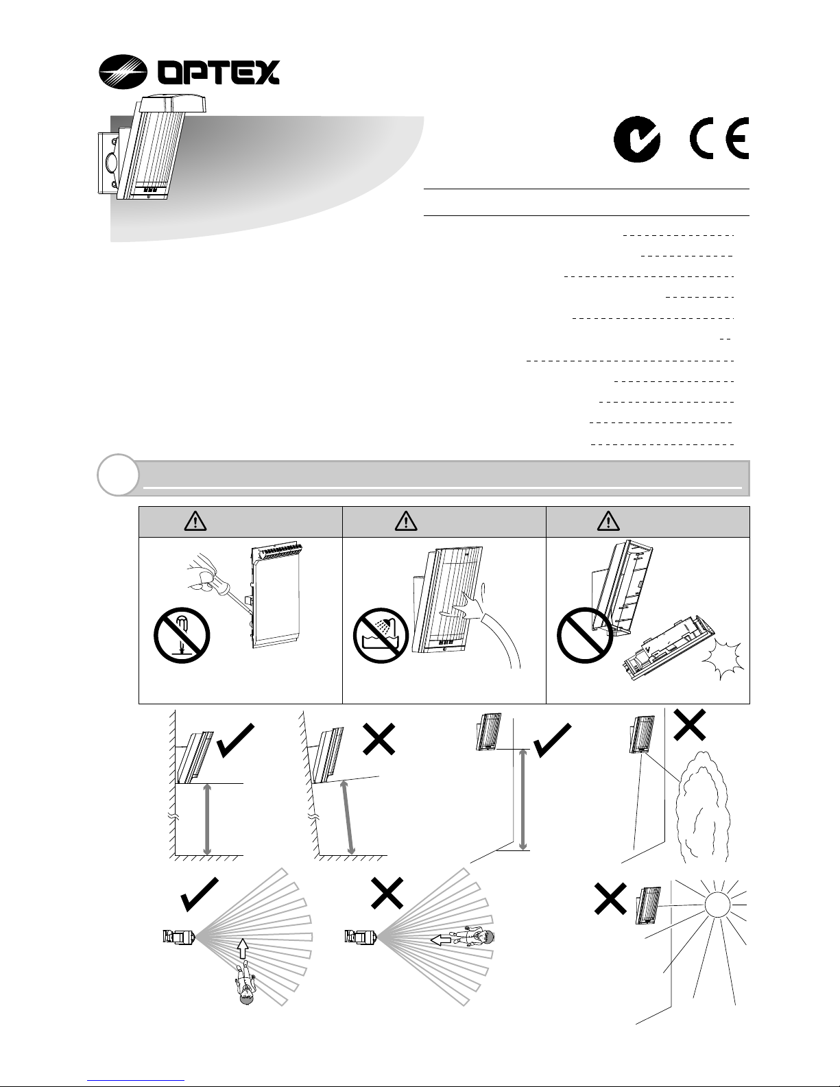
Warning Warning Caution
INSTALLATION HINTS
1
(1) INSTALLATION HINTS 1
(2) PARTS IDENTIFICATION 2
(3) KNOCKOUTS 2
(4) DETECTION AREA SETTING 3
(5) INSTALLATION 3
(6)
BRACKET INSTALLATION AND ADJUSTMENT
4
(7) WIRING 6
(8) FUNCTION SETTING 7
(9) OPERATION TEST 9
(10) LED FUNCTIONS 10
(11) SPECIFICATIONS 11
Parallel
2.5 - 3.0 m
(8.3 - 10 ft.)
Tilt
Never repair or modify product
Do not pour water over the
product
Mount securely
Mount the detector so that a majority of traffic flow is across the detection pattern.
-2-
䎃
䎃
䎃
䎃
䎃
䎃
䎃
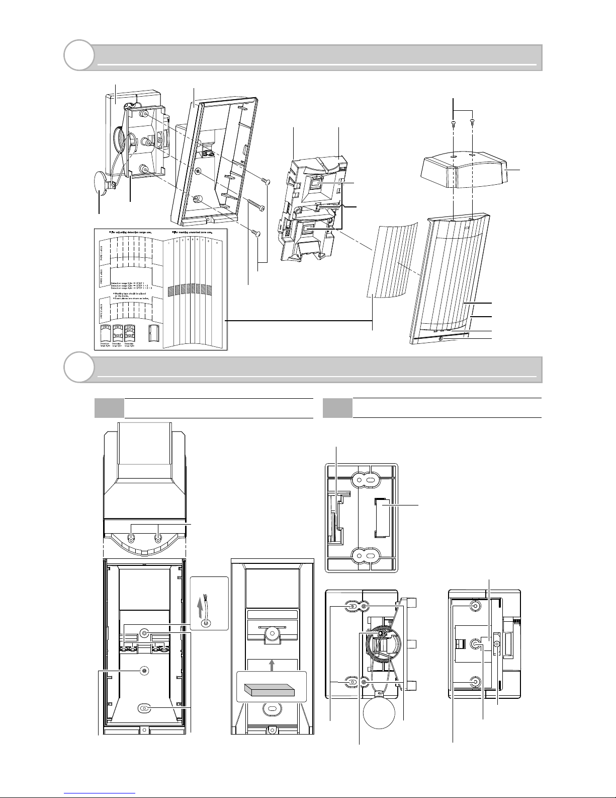
PARTS IDENTIFICATION
2
Hood
Screw (3×10 mm)
Screw (4×20 mm)
Bracket
Shaft cover
Lock screw (M4×35 mm)
Base
Bracket base
Main unitTerminals
Cover
Lock screw
Lens
LED indicator
Area
masking seal
PIR sensor
(Don not touch)
Anti-masking infrared LED
(HX-40AM only)
For wall
fastening
Wiring Hole
Wiring Hole
(Off-the-shelf) magnet switch
installation position
Adjustment screw
For switch
box fastening
For main unit fastening
Up-down
lock screw
Don’t touch
3-B Bracket
KNOCKOUTS
3
3-A Main unit
For wall fastening/bracket fastening
(installation pitch 83.5 mm (3.3 inch))
For bracket
up-down lock screw
For hood fastening
Wiring
knockout
Wiring sponge pad
-3-
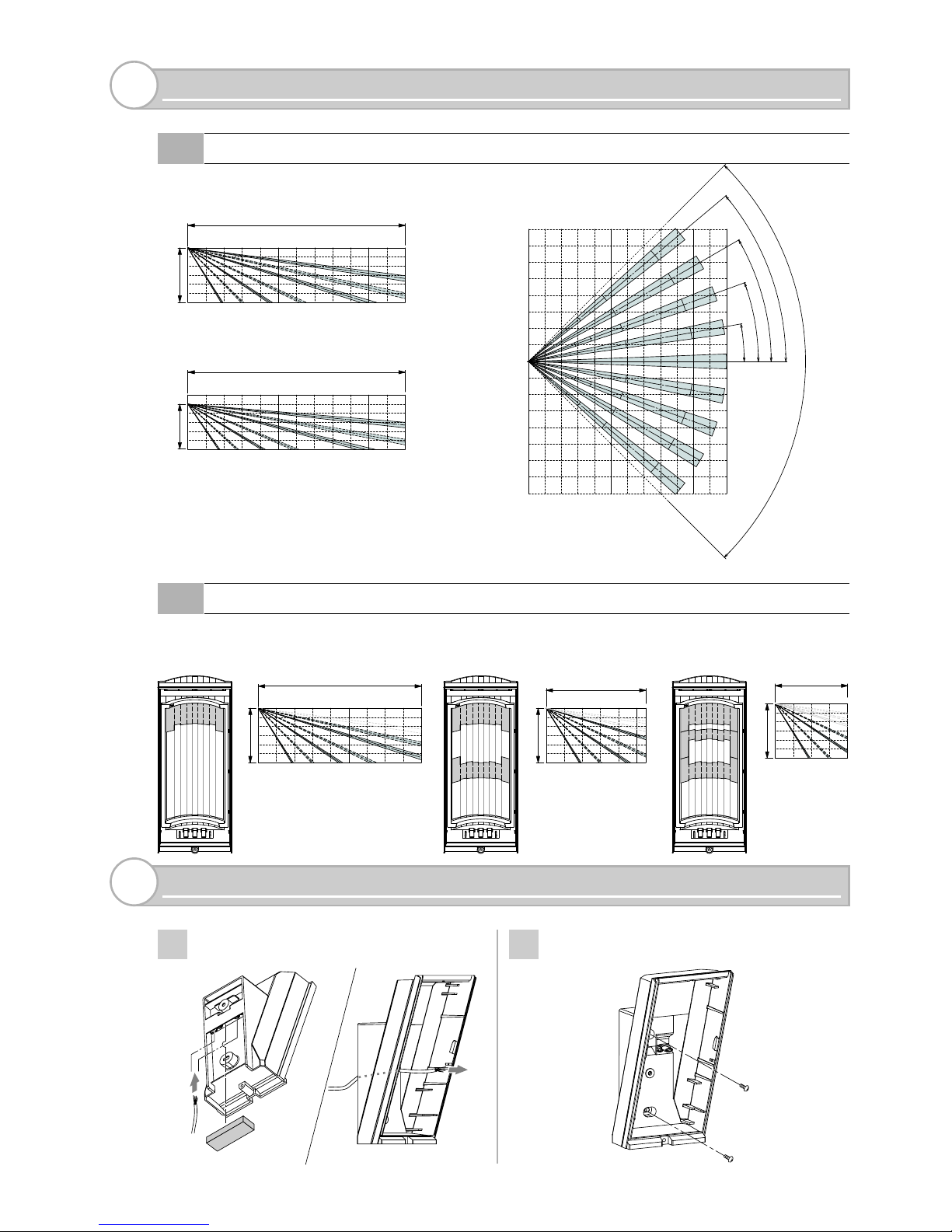
Side view of detection area
(Installation height 3.0 m (1 ft.) )
(Installation height 2.5 m)
To limit the detection distance, apply the appropriate masking seal. Note that there are three
different types of seal.
DETECTION AREA SETTING
4
4-B Detection Length Adjustment
4-A Detection Area
Top view of detection area
90°
4
0
°
30
°
20
°
10°
0
8 m
(26.7ft.)
8 m
(26.7ft.)
12 m (40 ft.)
12 m
(40 ft.)
3.0 m (10 ft.)
12 m (40 ft.)
2.5 m (8.3 ft.)
9.0 m (30 ft.)
3.0 m (10 ft.)
5.5 m (18.3 ft.)
3.0 m (10 ft.)
4.0 m (13.3 ft.)
3.0 m (10 ft.)
1
3
2
11
2
In
Out
Pass the wire through the base knockout.
Fasten the base to the wall.
INSTALLATION
5
1
2
Wiring sponge pad
-4-
In
In
Out
Out
Wiring sponge pad
1
2
3
4
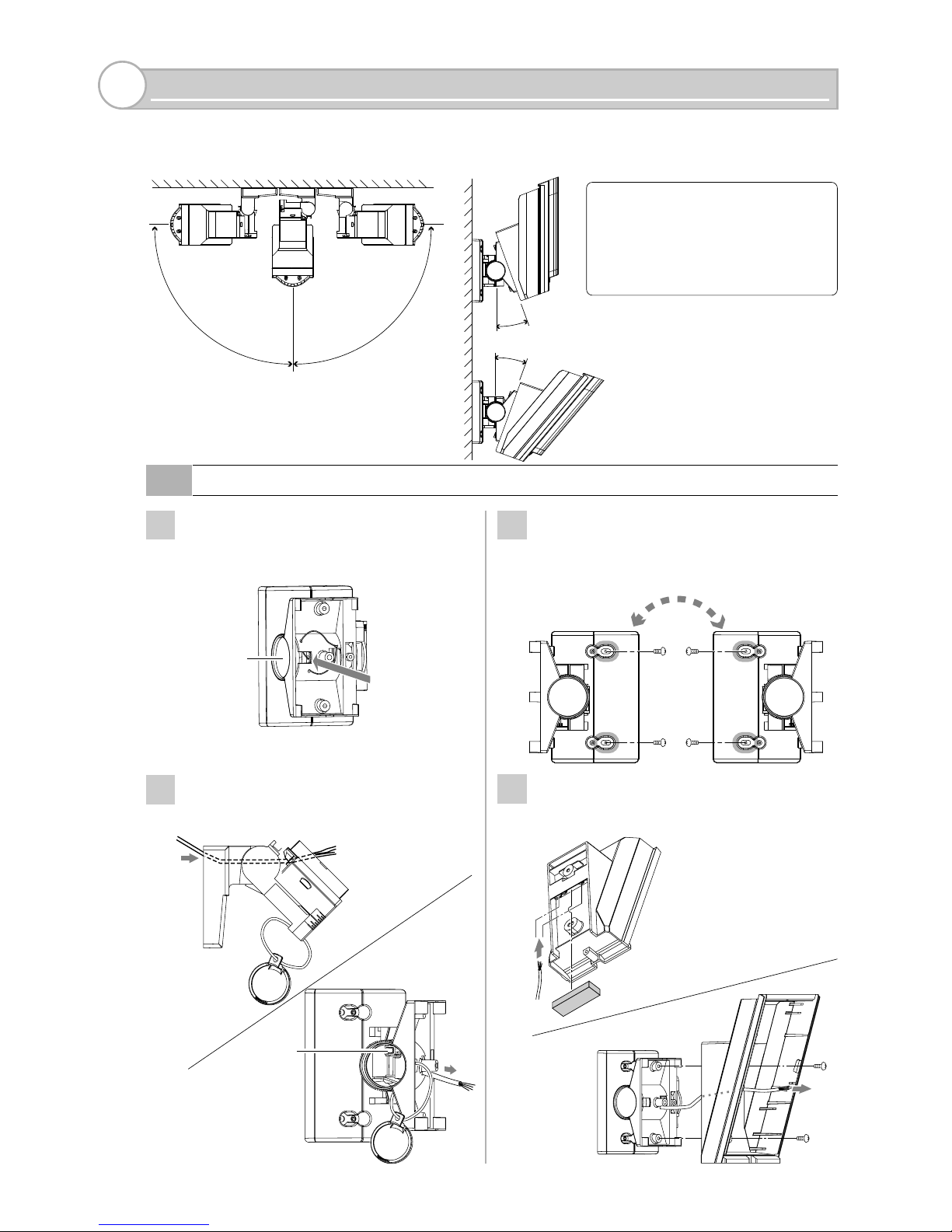
Push the shaft cover clip outwards to
remove the cover.
Loosen the adjustment screw, tilt the
bracket about 45° and pass through the
wire.
Fasten the bracket to the wall.
Change the bracket direction according
to whether the Main unit is to face left
or right.
Pass the wire through the base
knockout and install the base on the
bracket.
Adjustment
screw
BRACKET INSTALLATION AND ADJUSTMENT
6
20°
20°
90°
90°
6-A Bracket installation
Shaft cover
Push
Using the bracket makes it possible to adjust the unit through 180° degree.
In cases where the ground is uneven and therefore not parallel with the base of the unit, it is
possible to adjust the unit vertically by +/- 20 degree (see section 6-B)
Do not change the detection
distance with bracket.
Use the masking seal to
adjust the detection distance.
Caution>>
 Loading...