

Page 1

I
NSTA
L
LATION
INSTRUCTIONS
OFF
59
2536-0
1 BEFORE INSTALLATION
Warning
Failure to follow the
instructions provided
and improper handling
may cause death or
serious injury.
Caution
Failure to follow the
instructions provided
and improper handling
may cause injury and/or
property damage.
Do not touch the unit base or power terminals of the product with a wet hand. (Also, if the product is wet
after rain, do not touch it.) It may cause electric shock.
Never attempt to disassemble or repair the product. It may cause fire or damage to the devices.
[Handling of Batteries]
Fire, explosion and severe burn hazard. Do not recharge, short circuit, crush, disassemble, heat above 100°C,
Incinerate, or expose contents to water. Do not solder directly to the cell.
Do not pour water over the product. The water may enter and may cause damage to the devices.
Clean and check the product periodically for safe use. If any problem is found, do not attempt to use the product
as it is and inform your installer.
If you do not use the product for a long period of time, remove the battery. Keep it in a cool, dark area.
Dispose batteries according to local regulations.
This symbol indicates prohibition. The specific prohibited action is provided in and/or around the figure.
This symbol requires an action or gives an instruction.
The Outdoor Bell is used to attract attention when alarm signal is received from Control Panel, by activating its siren and strobe light.
The Bell Box has built-in tamper protection and low battery detection to monitor its operation status.
2 PARTS IDENTIFICATION
1. Mounting Holes x 4
2. Tamper Switch
The tamper switch protects the device from being opened or from being removed from mounting surface.
3. Function Switch Block
Contains 7 DIP Switches to enable the learning mode and to set the alarm period of siren and strobe light.
4. Securing Screw
To secure the cases from being open.
5. Power Switch
To enable/disable the power supply
3
5
+++
4
3 ACCESSORIES INCLUDED
In addition to the Bell Box, the following accessories are also included in the package
large wall plugs: 4 4x30 cross head fixing screws: 4 1.5V D alkaline cells: 4
4 DIP SWITCH POSITION TABLE
Remove the cover by unscrewing the single screw located at the bottom. In the middle
of the L-shaped PCB board, you can see a Jumper Switch Block which consists of 7
DIP Switches. The function of each DIP Switch is listed in the table on the right.
The DIP Switch is either ON or OFF. Top position indicates ON and bottom position
indicates OFF.
For further detail please see section Function Overview.
ON
SW1
OFF Normal operation
ON Learn-in mode
SW2 Strobe Activation
OFF only during siren alarm period
ON until alarm is disarmed
SW3 SW4 Alarm Length
OFF OFF 3 min.
ON OFF 5 min.
OFF
ON
SW5 Reserved
SW6 Memory Reset
OFF Normal
ON Clear Memory
SW7 Supervision
OFF Supervision function disable
ON Supervision function enable
Siren Learning
ON
ON
10 min.
1 second (test)
2
+
1
Page 2

SSiirreenn AAuuddiioo SSttrroobbee lliigghhtt iinnddiiccaattiioonn
down
beeps
5 POWER SUPPLY
The Bell Box is powered by 4 x D-cell alkaline batteries. It also features low battery voltage detection. When low battery is detected, a low battery signal
will be sent to the Control Panel along with regular signal transmissions for the Control Panel to display the status accordingly. The Bell Box will also
emit 5 beeps when armed/disarmed to notify the user of low battery condition.
6 SUPERVISION FUNCTION
When the Dip Switch #7 is slid to ON position, the Bell Box will conduct a Self-test Periodically by transmitting a supervisory signal once every 30-50
mins in normal operation mode.
If this signal is not received, the Control Panel will determine the particular Bell Box is out-of-order and report the event accordingly.
7 FUNCTION OVERVIEW
SIREN AUDIBLE PERFORMANCE
The siren produces a minimum of 104 dBA sound pressure at 1 meter range when activated.
For Burglar and Panic Alarm, the Bell Box gives a continuous alarm sound.
For Fire / Water alarm, the Bell Box gives an intermittent alarm sound of 2-sec siren followed by a 1 sec interval.
NNOOTTEE>>>>
The siren is silenced when either the programmed siren length expires or when the Control Panel is disarmed to turn off the siren. Please refer
to Dip Switch table above to set your desired alarm length through Dip Switch SW3 and SW4 setting.
STROBE (LED) LIGHT
When the Bell Box is activated, the LED strobe light will also flash to indicate the Bell Box is alarming. The duration of strobe light flash is determined by
Dip Switch SW2 setting. When set to OFF, the strobe light will flash according to the alarm length set by Dip Switch SW3 and SW4. When set to ON, the
strobe light will flash after the alarm length has expired until the control panel is disarmed.
ALARM MEMORY
If an alarm was triggered in your absence and the system was not disarmed before alarm length expiry, the Bellbox will sound a short alarm when the
system is disarmed to warn the user that an alarm has been triggered when he is away. This suggests that the intruder could still be within the premises.
ALARM LENGTH
When an alarm is activated by Control Panel, the Control Panel will notify the Bellbox to start alarming according to the panel’s own alarm length setting.
When the Panel’s alarm length expires, it will notify the Bellbox to stop alarm.
The Bellbox’s own alarm length setting, which is set by Dip Switch SW3&4, determines how long the Bellbox should activate alarm if no stop signal is
received from Control Panel:
For example
If the Panel alarm length is set longer than Bellbox alarm length, after an alarm is activated, instead of waiting panel alarm length to expire, the
Bellbox will stop alarming upon expiry of its own alarm length.
If the panel is under disarm mode and the Bellbox tamper switch is triggered, the Bellbox will activate alarm according to its own alarm length
setting since the panel is under disarm mode and will not activate alarm from tamper trigger.
TAMPER PROTECTION
The Bellbox is protected against any attempt to open the lid or to detach the bellbox from its mounting surface.
If the Bellbox detects a tamper condition, it will activate the siren & strobe light for the programmed alarm period. A tamper signal will be sent to the
Control Panel along with regular signal transmissions for the Control Panel to display the status accordingly. If the tamper condition persists, the Bellbox
will sound a series of five beeps either every time the system is armed or when the tamper is enabled, to indicate a fault.
Tamper feature can be disabled temporaily from the Control Panel using Siren Tamper control function. The Bellbox will stop tamper detection
temporarity for one hour. This function is mainly designed for replacing battery or changing Bellbox installation location. After one hour, The Control
Panel will automatically turn the function back ON after the duration. The tamper detection can also be enabled again manually using the Siren Tamper
function.
AUDIO & VISUAL STATUS INDICATION TABLE
The Bell Box will activate its siren and strobe light to notify the user of
system status, please refer to the table on the right.
NNOOTTEE>>>>
Siren Audio indication will be affected by the Confirmation
ON/OFF setting in your Control Panel settings.
FACTORY RESET
The siren can be reset and memory contents cleared by following
steps.
Step1. Remove the learnt-in Bell Box from Control Panel, refer
Step2. Remove the Bell Box front cover.
Step3. Slide the power switch to Off position, and then press the tamper switch once for discharging.
Step4. Set DIP SW 6 to ON position and put the power switch to ON position. The siren will produce a short confirmation tone.
Step5. Slide DIP SW 6 to OFF position. The Bell Box returns to normal mode.
to the operation manual of your Control Panel for details.
Arm/Home 1 beep* 3 LED flashes once
Disarm 2 beeps* Sequentially flashes for 1 cycle
Arm (Low Battery) 5 beeps 3 LED flashes for three times
Disarm (Low Battery) 5 beeps Sequentially flashes for 2 cycles
Arm (Tamper) 5 beeps 3 LED flashes for three times
Disarm (Tamper) 2 beeps* Sequentially flashes for 2 cycles
Previous alarm warning 3 secs beep Sequentially flashes for 2 cycles
Entry/Exit Sound
Count-
None
8 GETTING STARTED
LEARNING THE BELL BOX
Step1. Release the screws at the bottom of the Bell Box and pull the outer case out carefully. Locate the Function Switch Block.
Step2. Use a sharp object to slide Dip SW3 & SW4 on the Bell Box function switch block for your desired alarm length.
Step3. Put the Control Panel into the learning mode, refer to Control Panel manual for detail.
Step4. Slide Dip SW1 on the Bell Box function switch block to ON position. The LED 1 & 3 flash once with a short beep. The Bell Box is now in
Step5. If the Control Panel fails to receive a learning code, slide Dip SW1 back to OFF and then ON position to enable Bell Box to enter the
Step6. If the Control Panel receives the learning code, it will display Bell Box information accordingly. Refer to Control Panel manual to complete
Step7. After learning is completed, an acknowledgement signal will be sent to the Bell Box. When the acknowledgment is received, the Bell Box
NNOOTTEE>>>>
learning mode. After 3 seconds, the Bell Box will send out a learning code indicated by all 3 LED flashing.
learning mode again. Repeat the rest of the learning process.
learning process.
sounds a short beep with LED 1&3 flashing once to indicate that learning process is successful.
Page 3
If the learning process fails, please remove the Bell Box from the control panel and repeat the step 3-7 again.
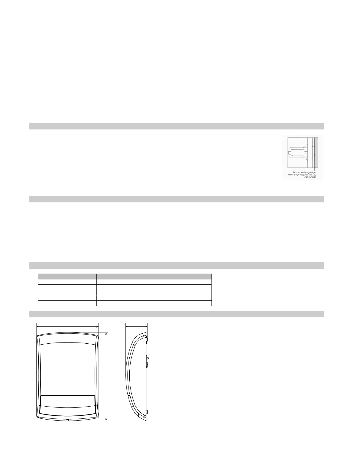
202
71
287
Unit: mm
Step8. Slide Dip SW1 on the Bell Box to OFF position. The Bell Box leaves learning mode. If you don’t slide Dip SW1 back to OFF position, the
Bell Box will automatically leave the learning mode one hour after it enters the learning mode.
PROGRAMING THE BELL BOX
Use the Control Panel “Program Siren” function to adjust Bellbox settings.
GENERAL SIREN FUNCTION
Changing general siren function will affect the setting of all learned in siren / Bellbox.
SIREN TAMPER
If it is set to “ON”, the Bell Box will ativate alarm when the tamper switch is triggered.
If it is set to “OFF”, the Bell Box will remain silent when the tamper switch is triggered.
NNOOTTEE>>>>
CONFIRM
If it is set to “ON”, the Bell Box will sound beeps when the system is armed or disarmed.
If it is set to “OFF”, the Bell Box will remain silent when the system is armed or disarmed.
ENTRY SOUND
If it is set to “ON”, the Bell Box will sound beeps when the Entry timer is activated.
If it is set to “OFF”, the Bell Box will remain silent when the Entry timer is activated.
If the siren tamper is set as disabled (OFF), it will automatically revert to enable (ON) after about an hour if it is not switched back manually.
9 INSTALLING THE BELL BOX
The tamper switch plunger protrudes through the back of the unit. If the Bell Box is pulled off from the wall, the alarm will be activated. Ensure it is fully
depressed when the Bell Box is mounted. If there is a gap, pack with a suitable spacing material.
Step1. Find the location where the Bell Box is to be mounted.
Step2. Using the large screws and wall plugs provided, mount on wall through the 4 x mounting holes.
Step3. Fix the Bell Box cover with the securing screw.
Step4. Enable tamper switch by selecting the tamper enable/disable menu on the Control Panel (please refer to the
Step5. Check if the installation is successful by arming and disarming the Control Panel.
NNOOTTEE>>>>
Step6. The installation is now completed.
Manual of Control Panel for details).
If 5 short-beeps are noticed while arming, it means the tamper is not correctly set. Check to ensure that tamper is
properly set and then test from Control Panel again.
10 CHANGING THE BATTERY
Step1. Find the Control Panel’s Program Siren menu and disable the Siren Tamper function. The Bell Box will emit a beep when the tamper is
Step2. Release the screws at the bottom of the Bell Box and pull the outer case out carefully.
Step3. The battery compartment is a large box in the Bell Box with a lid secured with 4 screws.
Step4. Remove the four screws and take off the compartment lid.
Step5. Remove the old batteries and press the Tamper Switch twice to discharge.
Step6. Insert the new D cell alkaline batteries into the battery compartment. Orient the batteries according to the correct polarity.
Step7. The Bell Box will emit beeps and flash when the last battery is inserted.
Step8. Replace the battery compartment lid with the four screws taking care not to over tighten.
Step9. Enable the Siren Tamper funciton in Control Panel menu. The Bell Box will sound a beep to indicate the tamper protection is now
disabled.
activated.
11 SPECIFICATIONS
Model GEN-OSR
Frequency 433.82 MHz
Power source D size alkaline battery: 4 units
Battery life Approx. 2.5 years (1 activations per year, 25°C)
Operating conditions -10°C to +55°C (up to 85% non-condensing)
Weight 1300 g (including battery)
12 DIMENSIONS
 Loading...