

Page 1

WIRELESS OUTDOOR
WIRELESS OUTDOOR
DETECTOR
DETECTOR
FTN-RRHW/FTN-RRIX
FTN-RRHW/FTN-RRIX
FTN-RR2G/FTN-RRDS
FTN-RR2G/FTN-RRDS
6/13/2017
59-2624-0
INSTALLATION INSTRUCTIONS
FTN-RRHW Honeywell 5800 Series Compatible
FTN-RRIX Interlogix 319.5MHz Compatible
Product is not produced by, endorsed by, nor is officially associated with Honeywell, Interlogix, 2GIG, QOLSYS or DSC.
FEATURES
• Narrow Angle Detection
• Detection Range Adjustability (2m / 5m)
• Intelligent ‘AND’ logic
• Horizontal Adjustability
• Tamper Output
Install in accordance with the Standard for Installation and
Classification of Burglar and Holdup Alarm Systems, UL 681.
FCC NOTICE
This device complies with Part 15 of the FCC rules. Operation is
subject to the following two conditions:
(1) This device may not cause harmful interference.
(2) This device must accept any interference that may be received,
including interference that may cause undesired operation.
Changes or modifications not expressly approved by the
Resolution Products, Inc. could void the user’s authority to operate
this equipment.
IC NOTICE
This device complies with Industry Canada license-exempt RSS
standard(s). Operation is subject to the following two conditions:
(1) This device may not cause interference, and
(2) This device must accept any interference, including interference
that may cause undesired operation of the device.
Le présent appareil est conforme aux cnr d’Industrie Canada
applicables aux appareils radio exempts de licence. L’exploitation
est autorisée aux deux conditions suivantes:
(1) L’appareil ne doit pas produire de brouillage, et
(2) L’utilisateur de l’appareil doit accepter tout brouillage
radioélectrique subi, même si le brouillage est susceptible d’en
compromettre le fonctionnement.
“Honeywell”, “2GIG”, “Interlogix”, “DSC” are trademarks owned by
Honeywell International, Inc, Nortek Security & Control LLC, United
Technologies Corporation, and Tyco Safety Products Canada LTD,
respectively.
OPTEX Inc. products will function with one of either Honeywell,
2GIG, Interlogix, or DSC systems. However, no OPTEX Inc.
product is produced by, endorsed by, nor is officially associated
with Honeywell, 2GIG, Interlogix, DSC.
OPTEX Inc. recommends verifying proper enrollment and
operation, per control panel installation instructions, at installation.
FTN-RR2G 2GIG Compatible
FTN-RRDS DSC 433MHz Compatible
CONTENTS
1 INTRODUCTION
1-1 BEFORE INSTALLATION .................. 2
1-2 ZONE CONFIGURATION ..................3
1-3 PARTS IDENTIFICATION.................. 3
1-4 DETECTION AREA ............................ 4
2 INSTALLATION
2-1 WIRING DIAGRAM ............................4
2-2 ENROLLING TO PANEL.................... 5
2-3 MOUNTING........................................ 9
3 WALK TEST
3-1 WALK TEST ..................................... 12
4 DIP SWITCH SETTING
4-1 WALK TEST MODE .........................12
4-2 BATTERY SAVING TIMER .............. 13
4-3 ALARM & TROUBLE OUTPUT........ 13
4-4 LED .................................................. 13
4-5 PIR SENSITIVITY ............................ 13
5 OTHERS
5-1 LED LIGHT PATTERN ..................... 14
6 BATTERY
6-1 HOW TO REPLACE BATTERY....... 15
6-2 BATTERY LIFE ................................15
7 SPECIFICATIONS
7-1 SPECIFICATIONS ........................... 16
7-2 DIMENSIONS................................... 16
- 1 -
Page 2
INTRODUCTION
1
1-1
BEFORE INSTALLATION
Warning
Caution
Avertissement
Attention
The check
Le signe de coche indique une recommandation.
Failure to follow the instructions provided with this indication and improper
handling may cause death or serious injury.
Failure to follow the instructions provided with this indication and improper
handling may cause injury and/or property damage.
Le non respect des instructions données avec ce signe et une mauvaise
manipulation peuvent causer la mort ou des blessures graves.
Le non respect des instructions données avec ce signe et une mauvaise
manipulation peuvent causer des blessures et/ou des dommages aux biens.
mark indicates recommendation. The nix sign indicates prohibition.
Le signe de négation indique une interdiction.
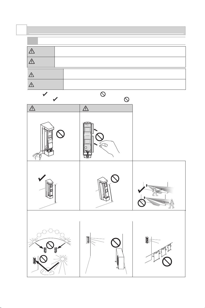
Warning/Avertissement
Do not remove the PCB.
Ne pas enlever le PCB.
Mounting height. Keep the detector parallel to the ground. Consider the direction a person is
Hauteur de montage.
0.8 – 1.2 m
(2'7" – 3'11")
Parallel
Parallèle
Caution/Attention
Do not touch the PCB except for the
DIP switch.
Maintenir le détecteur parallèle au sol.
Ne pas toucher le
PCB sauf les
interrupteurs DIP.
Tilt
Ne pas incliner
approaching from, as well as the
detection area.
Tenir compte de la direction d’approche
d’une personne de même que de la
zone de détection.
Install the detector in a place where it is free from false alarm factors. For example:
Installer le détecteur dans un emplacement ne présentant pas de cause de fausses alarmes. Par exemple :
• Direct Sunlight and reflection •
• Lumière solaire et réflexion
Heat source
•
Source de chaleur
•
Objects moving in the wind
Objets bougeant au vent
•
- 2 -
Page 3
1-2
ZONE CONFIGURATION SUGGESTIONS
Set up “FITLINK” according to location as desired. Below are zone configurations for typical location types.
Location
Alarm Output Report to CMS
Disarm Away Stay Alarm Trouble
Front Porch;
Backyard Carport;
Gate Entrance;
No
No
Deck
Crawl Space;
Basement;
No
Storage Shed;
Garage or
Sliding Glass Door;
Screened in Porch;
No
Sunroom
Driveway;
Sidewalk;
No
No
Public Areas
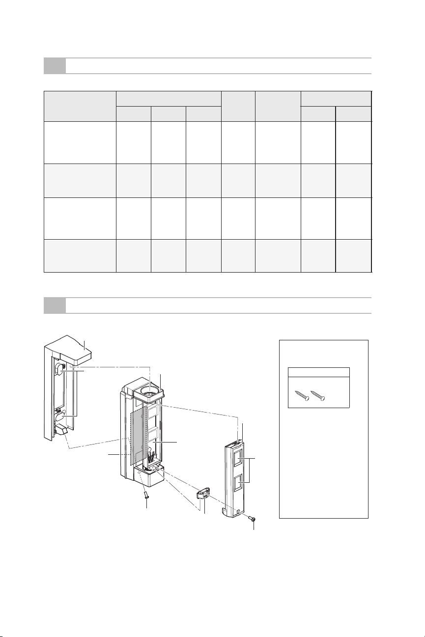
1-3
PARTS IDENTIFICATION
Mounting base
Screw cap
Instant
Alarm
Entry
delay 2
Bracket
No
Instant
Alarm
Entry
delay 2
No
Panel
Event
Yes
Yes
Yes
No
Chime
Toggle
On or Off
On during
disarm
On during
disarm
Toggle
On or Off
Accessories>>
Screw kit
No
Yes
Yes
No
For wall mounting
Screw (3 × 20 mm)
Yes
Yes
Yes
Yes
Transmitter
compartment
Screw
Main unit
Fixture
- 3 -
Main unit
cover
Lens
Screw
Note>>
FCC ID
FTN-RRHW: U5X-RE201X
FTN-RR2G: U5X-RE201X
FTN-RRIX: U5X-RE101X
FTN-RRDS: U5X-RE301
IC ID
FTN-RRHW: 8310A-RE201
FTN-RR2G: 8310A-RE201
FTN-RRIX: 8310A-RE101
FTN-RRDS: 8310A-RE301
Page 4
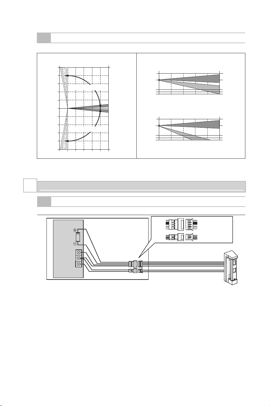
1-4
DETECTION AREA
Top view Side view
(m)
5
4
3
Adjustable range: 95° (by 5° pitch)
2
1
0
1
2
Adjustable range: 95° (by 5° pitch)
3
4
5
1
INSTALLATION
2
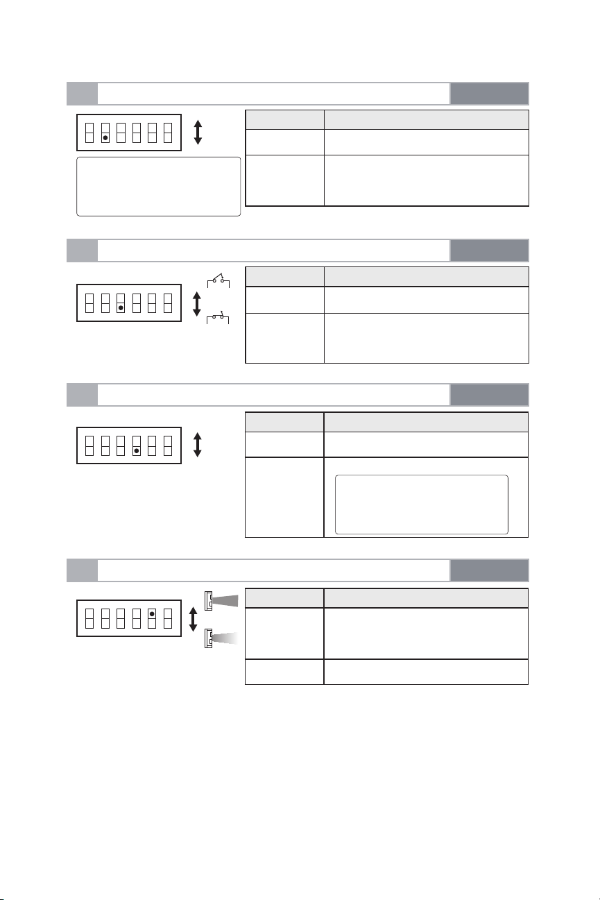
2-1
WIRING DIAGRAM
- Overall wiring diagram
Transmitter
GND
10 234 5
A
B
(m)
Bracket
5 m detection length
(m)
0
0.8
1.0
1.2
10 2 3 4 5
2 m detection length
(m)
0
0.8
1.0
1.2
10 2 3 4 5
Red
Black
White
Yellow
Green
Blue
(m)
(m)
Red: Power input (+)
Black: Power input (-)
White: Alarm
Yellow: Alarm
Green: Tamper
Blue: Tamper
Main unit
Note>>
• The battery in the transmitter is shared with the detector.
• Connection for TROUBLE is used when monitoring for Tamper.
- 4 -
Page 5

2-2
ENROLLING TO CONTROL PANEL
Enrolling to Honeywell LYNX Touch L5210/L7000 Series
1. Place the panel into wireless enrollment mode and then trip the tamper three times.
2. Set “Loop Number” to 1.
3. Set “Device type” to “Other”.
4. Set “Response Type” and “Alarm Report” according to following table.
5. Set “Chime” to your preferred type.
6. Set “Supervision” to “Supervised”.
Location Response Type
Front Porch; Backyard Carport;
Gate Entrance; Deck
Crawl Space; Basement;
Storage Shed
Garage or Sliding Glass Door;
Screened in Porch; Sunroom
Driveway; Sidewalk;
Public Areas
Silent Burglary
Perimeter
Entry Exit 2
Silent Burglary
Alarm Report
No
Yes
Yes
No
Enrolling to Honeywell Residential Vista Panels
1. While in program mode, press *56 to enter Zone Programming Menu Mode.
2. Select 0 or 1 to determine if you will “confirm” the sensor after learning it.
3. Enter the zone number that you wish to program (or 00 to exit zone programming). Press [*] to continue.
4. A summary display appears, press [*] to continue.
5. Enter “Zone Type” according to table.
6. Enter “Partition No.”
7. Enter “Report codes” according to table.
8. Enter “Input Type” to “3” = RF (supervised RF transmitter).
9. Learn or input transmitters serial number. (To learn FITLINK, trip the tamper three times.)
10. Change “Loop Number” to 1.
Location Zone Type
Report Codes
Front Porch; Backyard Carport;
Gate Entrance; Deck
Crawl Space; Basement;
Storage Shed
Garage or Sliding Glass Door;
Screened in Porch; Sunroom
Driveway; Sidewalk;
Public Areas
Type 24
Silent Burglary
Type 03
Perimeter Burglary
Type 02
Entry Exit 2
Type 24
Silent Burglary
- 5 -
00
Other than 00
Other than 00
00
Page 6

2-2
ENROLLING TO CONTROL PANEL
Enrolling to 2GIG GC2/GC3
1. Select “RF Sensor #” (01 to 48).
2. Select “Sensor Type” according the following table.
3. Select “Sensor Equipment Code” as “[0000] Other or [0609] Existing Motion Detector”.
4. Select “Sensor Other Equip code as “[0]” (this menu only appears if [0000] Other was selected in the
previous menu.
5. At the “Sensor Serial Number” menu, press shift, then press Learn, and then trip detector tamper switch.
6. Select “Equipment Age” as “New”.
7. Select “Loop Number ” as “Loop 1”.
8. Select “Dialer Delay” as “Enabled”.
9. Edit “Voice Descriptor” according to location.
10. Select “Sensor Reports” according to following table.
11. Select “Sensor Supervised” to “Enabled”.
12. Select the desired chime.
Location Sensor Type
Front Porch; Backyard Carport;
Gate Entrance; Deck
Crawl Space; Basement;
Storage Shed
Garage or Sliding Glass Door;
Screened in Porch; Sunroom
Driveway; Sidewalk;
Public Areas
(23) No Response Type
(03) Perimeter
(02) Exit/Entry 2
(23) No Response Type
Sensor Reports
No
Yes
Yes
No
- 6 -
Page 7

2-2
ENROLLING TO CONTROL PANEL
Enrolling to DSC PowerSeries
1. Put control panel into learn sensor mode.
2. Push tamper switch to enroll FITLINK.
3. Press [*] key to confirm ID.
4. Enter [zone #].
5. Enter [zone type] according to the following table.
6. Press the tamper again to “Activate the Device for Test”.
7. Set “Zone Attributes” according to following table.
Location Zone Types
Front Porch; Backyard Carport;
Gate Entrance; Deck
Crawl Space; Basement;
Storage Shed
Garage or Sliding Glass Door;
Screened in Porch; Sunroom
Driveway; Sidewalk;
Public Areas
24-hour Non-Alarm
Instant
Delay 2
24-Hour Non-Alarm
Zone Attributes
Set “Chime” ON or OFF
Keep as defaults
Keep as defaults
Set “Chime” ON or OFF
Enrolling to Qolsys IQ PANEL
1. Enter Settings Menu and select "Installation".
2. Select "Security Sensors" and then select "Auto Learn Sensor".
3. Trip the tamper to enroll within 2min.
4. Panel will chime and display the sensor's code. Select OK to confirm.
5. Set "Sensor Type" to "Motion".
6. Set "Sensor Name" to the correct name from the list.
7. Set "Chime Type" to your preferred type.
8. Set “Sensor Group” according to following table.
9. Select "Add New" to complete.
Location Sensor Group
Front Porch; Backyard Carport;
Deck; Gate Entrance
Crawl Space; Basement;
Storage Shed
Garage or Sliding Glass Door;
Screened in Porch; Sunroom
Driveway; Sidewalk;
Public Areas
25: Safty Motion
17: Away - Instant
Motion
20: Away - Delay
Motion
25: Safety Motion
- 7 -
Page 8

2-2
ENROLLING TO CONTROL PANEL
Enrolling to Interlogix Simon XTi
1. Put control panel in learn sensor mode.
2. Push tamper switch to enroll FITLINK.
3. Enter “Sensor Number”
4. Select “Sensor group” according to following table.
5. Change “Sensor Name” of Item 1 to the correct name from the list.
6. Press save to save the changes.
Location Sensor Type
Front Porch; Backyard Carport;
Gate Entrance; Deck
Crawl Space; Basement;
Storage Shed
Garage or Sliding Glass Door;
Screened in Porch; Sunroom
Driveway; Sidewalk;
Public Areas
25: Local special chime
13: Instant perimeter
10: Entry/exit delay
25: Local special chime
Enrolling to Interlogix Concord 4/Concord Express
1. Put control panel in learn sensor mode.
2. Select partition.
3. Enter the sensor group according to following table.
4. Push tamper switch to enroll FITLINK.
5. Exit learn sensor mode
Enrolling to Interlogix AdvisorOne
1. From the Sensors screen, press LEARN RF.
2. Select the sensor group according to following table.
3. Push tamper switch to enroll FITLINK.
4. Press CLOSE.
5. Press EDIT to edit the options.
6. Select “Chime Mode” as desired.
7. Press SAVE and CLOSE.
Location Sensor Type
Front Porch; Backyard Carport;
Gate Entrance; Deck
Crawl Space; Basement;
Storage Shed
Garage or Sliding Glass Door;
Screened in Porch; Sunroom
Driveway; Sidewalk;
Public Areas
25: Local special chime
13: Instant perimeter
11: Supplementary
Extended Delay
25: Local special chime
- 8 -
Page 9

2-3
MOUNTING
Remove the mounting base.
1
2
1
Mount the mounting base on the wall.
3
Mounting height:
0.8 – 1.2 m
100 mm
Screw (3 × 20 mm)
Screw (3 × 20 mm)
Note>>
• Transmitter needs to be enrolled to
reciever before installing the detector.
Open the knockout.
2
Use this knockout screw hole to mount the
base, when making the wall tamper switch
effective. If the main unit is peeled off from
a wall, this plastic part will be cracked and
remain on a wall, activating the tamper
switch.
Mounting base
Joint screw
knockout
Joint screw
knockout
Attach the bracket and main section.
4
1
2
Open the main unit cover
5
Note>>
• Be sure to set the screw cap after installing the mounting base.
- 9 -
2
1
Page 10

Determine the horizontal detection angle and attach the fixture.
6
Notes>>
Note>>
• To make adjustments, remove the fixture.
2
1
3
• Align the detection area parallel to
the wall to reduce interference with
the wall.
Note>>
• Check that the fixture and
bracket engage correctly.
• When the unit is mounted on the
corner to look ahead along the wall,
choose the guide-mark located on
the opposite side of the wall.
- 10 -
• When the unit is mounted on the
wall and the detection pattern is at
90 degrees, choose the corresponding engraved guide mark.
Page 11

Determine the detection length. (2 m or 5 m)
8
5 m detection length
(Factory default)
Side view
(m)
0
0.8
1.0
1.2
Attach the fixture.
9
10 2 3 4 5
If 2 m is required, rotate the lower lens
180 degrees.
Note>>
• Do not remove the upper lens.
2 m detection length
Side view
(m)
0
0.8
1.0
1.2
(m)
Attach the main unit cover.
10
10 2 3 4 5
(m)
Fixture
Perform walk test.
11
For details, refer to 3-1.
12
- 11 -
Note>>
• To prepare for walk test, check that
DIPswitch 1 (WALKTEST MODE) is
set to “ON (TEST)” before attaching
main unit cover.
After walk test is complete, set DIP
switch 1 (WALK TEST MODE) from
“ON” to “OFF”.
Note>>
• The battery life will be shortened
unless the DIP switch 1 is set to
“OFF”.
Page 12

WALK TEST
3
3-1
Set the DIP switch 1 (WALK TEST
1
MODE) to “ON (TEST)”.
WALK TEST
Check that LED lights for 2 seconds
2
when the intended object is detected.
DIP switch
ON
Note>>
• The switch is set to “ON (TEST)” by
factory default.
Set the DIP switch 1 (WALK TEST MODE) to “OFF (NORM)”.
3
DIP SWITCH SETTING
4
ON
1234 5 6
●: Factorydefault
1 2 3 4 5 6
DIP switch
ON
1 2 3 4 5 6
DIP switch
1 WALK TEST MODE
2 BATTERY SAVING TIMER
3 ALARM & TROUBLE OUTPUT
4 LED
5 PIR SENSITIVITY
6 N/A
Detected
Not detected
Notes>>
• The battery life will be shortened unless
the DIP switch 1 is set to “OFF”.
• To use the LED in normal operating
condition, set the DIP switch 4 to “ON”.
Do not touch the
PCB except for
the DIP switch.
4-1
WALK TEST MODE
ON
1 2 3 4 5 6
TEST
NORM
DIP switch 1
Position Function
TEST
(Factory
default)
NORM
• The LED lights irrespective of the DIP
switch 4 (LED) setting.
• The DIP switch 2 (BATTERY SAVING
TIMER) setting is inactive.
• The LED lights depending on the DIP
switch 4 (LED) setting.
• The DIP switch 2 (BATTERY SAVING
TIMER) setting is active.
- 12 -
Page 13
4-2
BATTERY SAVING TIMER
5S
120S
ON
1 2 3 4 5 6
Note>>
• The detector will not generate
alarms at intervals shorter
than the specified time.
DIP switch 2
Position Function
5S 5 sec.
120S
(Factory
default)
120 sec.
4-3
ALARM & TROUBLE OUTPUT
ON
1 2 3 4 5 6
4-4
LED
ON
1 2 3 4 5 6
4-5
PIR SENSITIVITY
ON
1 2 3 4 5 6
N.O.
N.C.
STD
LOW
ON
OFF
DIP switch 3
Position Function
N.O.
N.C.
(Factory
default)
Position Function
ON LED ON
OFF
(Factory
default)
Position Function
STD
(Factory
default)
N.O. output
N.C. output
DIP switch 4
LED OFF
Note>>
• If the LED lights, check the DIP
switch 1 (WALKTEST MODE)
setting.
DIP switch 5
Normal sensitivity
LOW Low sensitivity
- 13 -
Page 14

OTHERS
5
5-1
LED LIGHT PATTERN
The following explains the LED light pattern.
Warm-up
Note>>
• The LED blinks even if the DIP
switch 4 (LED) is set to “OFF”.
Alarm
LED
Blink Light OFF
rotacidni DELnoitidnoc rotceteD
Blinks for approx. 120 seconds.
Lights for 2 seconds.
- 14 -
Page 15

BATTERY
6
The detector shares the battery with the transmitter.
6-1
HOW TO REPLACE BATTERY
Remove the bracket and main
1
section.
2
1
Attach the bracket and main section.
3
1
2
6-2
BATTERY LIFE
The values indicated are only for reference on each condition.
The sensor will send low battery transmissions to the control panel.
CR123A (3 V, 1300 mAh)
Battery LifeAlarm trigger per day
150
500
Approx. 5 years
Approx. 2 years
Replace the battery.
2
Install a new battery.
- 15 -
Page 16

SPECIFICATIONS
7
7-1
SPECIFICATIONS
Model FTN-RRHW FTN-RRIX
Detection method Passive infrared
PIR coverage 16'5" × 3'3" (5 × 1m)
Detection length limit 6'7", 16'5" (2 m, 5 m)
Detection width 3'3" wide at 16'5" / 24" wide at 6'7"
Detectable speed
Sensitivity
Power source
Current draw
Alarm period
Warm-up period
Alarm output N.C./N.O. Selectable-Solid State Switch 10 V DC 0.01 A (max.)
Trouble output N.C./N.O. Selectable-Solid State Switch 10 V DC 0.01 A (max.)
LED indicator
RF Interference
Operation temperature
Environment humidity
Weatherproof
Mounting
Mounting height
Accessories
*Specifications and design are subject to change without prior notice.
7-2
DIMENSIONS
Enable: During DIP switch 1 (WALK TEST MODE) or DIP switch 4 (LED) ON
Disable: During normal operation
Light/Blink:
Warm-up, alarm
6.4 oz. (180g) without wireless transmitter and batteryWeight
1' – 4'11"/s (0.3 – 1.5 m/s)
3.6°F (at 2'/s) (2.0°C (at 0.6 m/s))
CR123A Lithium battery
11.2μA standby / 23mA max. at 3 V DC
2.0 ±1.0 sec.
Approx. 120 sec. (LED blinks)
No alarm 10 V/m
-4 to +140°F (-20 to +60°C)
Wall (Outdoor, Indoor)
2'7" to 3'11" (0.8 to 1.2 m)
screw (3 × 20 mm) × 2
FTN-RR2G FTN-RRDS
95% max.
IP55
NOTE
These units are designed to detect an intruder and activate an
Unit: in (mm)
alarm control panel.
Being only a part of a complete system, we cannot accept
responsibility for any damages or other consequences resulting
from an intrusion.
2.07 (52.6)
OPTEX INC. ( U.S.)
URL: http://www.optexamer ica.com
OPTEX DO BR ASIL LTDA. ( Brazil)
URL: http://www.optex.net /br/es/sec
OPTEX (EURO PE) LTD. / EMEA HQ (U.K.)
URL: http://www.optex-eu rope.com
OPTEX TECHN OLOGIES B.V. (The Nether lands)
URL: http://www.optex.eu
2.66 (67.5)
For programming technical support: 877-260-5578
For OPTEX support: 800-966-7839
support@optexamerica.com
www.optexamerica.com
6.94 (176.4)
OPTEX SECUR ITY SAS (France)
URL: http://www.optex-se curity.com
OPTEX SECUR ITY Sp. z o.o. (Poland)
URL: http://www.optex.co m.pl
OPTEX PINN ACLE INDIA , PVT., LTD. (India)
URL: http://www.optex.net /in/en/sec
- 16 -
OPTEX KORE
URL: http://www.optexkorea.c om
OPTEX (DONGG UAN) CO.,LTD.
SHANGHAI O FFICE (China)
URL: http://www.optexchina.c om
OPTEX (Thai land) CO., LTD. (Thailand)
URL: http://www.optex.net /th/th
A CO.,LTD. (Korea)
Copyright (C) 2 017 OPTEX CO.,LTD.
 Loading...