

Page 1
FitLink QUICK REFERENCE GUIDE
1
3
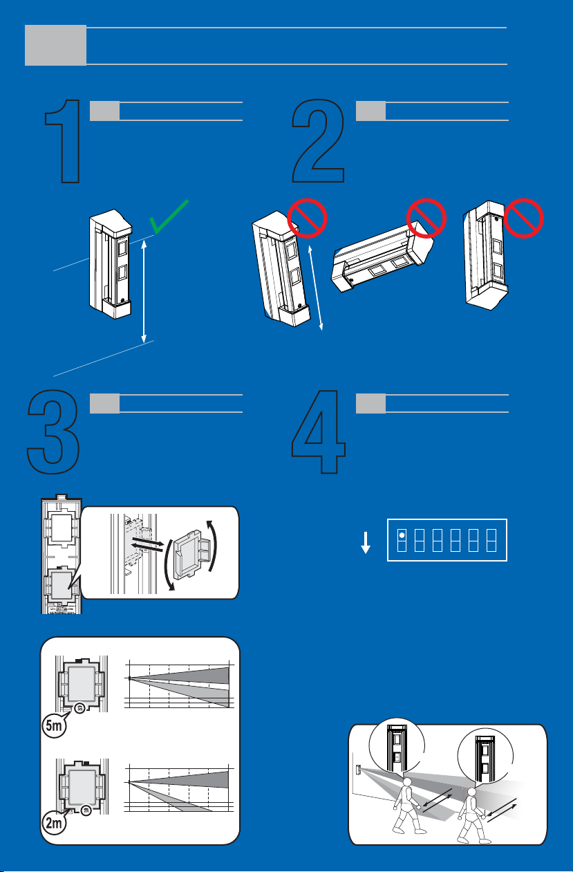
MOUNTING HEIGHT
It’s extremely important to stay
within recommend heights of
2ft.,7in. to 3ft.,11in. to prevent
missed and unwanted alarms.
2’7” to 3’11”
(0.8 to 1.2m)
Parallel
DETECTION RANGE
Make sure to adjust detection range to
best fit application.
16.4' (5m) or 6.6' (2m)
If 6.6’ (2m) is required, rotate the
lower lens 180 degrees.
2
4
MOUNTING POSITION
Make sure to keep detector vertical and
level to the ground. When mounting
detector, do not tilt, turn upside down, or
mount horizontal. Detector should alway be
mounted vertical for best operation.
Horizontal Upside DownTilt
FINAL TESTING
Make sure to insert battery to power
detector and perform Walk Test.
After unit has been installed and
programmed, make sure to walk test and
confirm detector is performing affectively.
Once confirmed be sure to flip dip switch #1
from TEST (factory setting) to NORMAL.
Note>>
Do not remove the upper lens.
16.4ft. (5m) detection length (Factory default)
(ft)
3.9
3.3
2.6
3.30 6.6 9.8 13 16.4
6.6ft. (2m) detection length
(ft)
3.9
3.3
2.6
0 6.6 9.8 13 16.4
Side view
Side view
TEST
ON
NORM
TEST:
Regardless of DIP switch 4 (LED) and DIP
switch 2 (BATTERY SAVING MODE)
settings, LED will illuminate and detector will
trigger every time.
This is used for Walk Test ONLY.
NORMAL:
The LED lights depending on the DIP switch
4 (LED) setting and DIP switch 2 (BATTERY
SAVING MODE) setting is active.
(ft)
(ft)
1 2 3 4 5 6
Detected
Not detected
Page 2
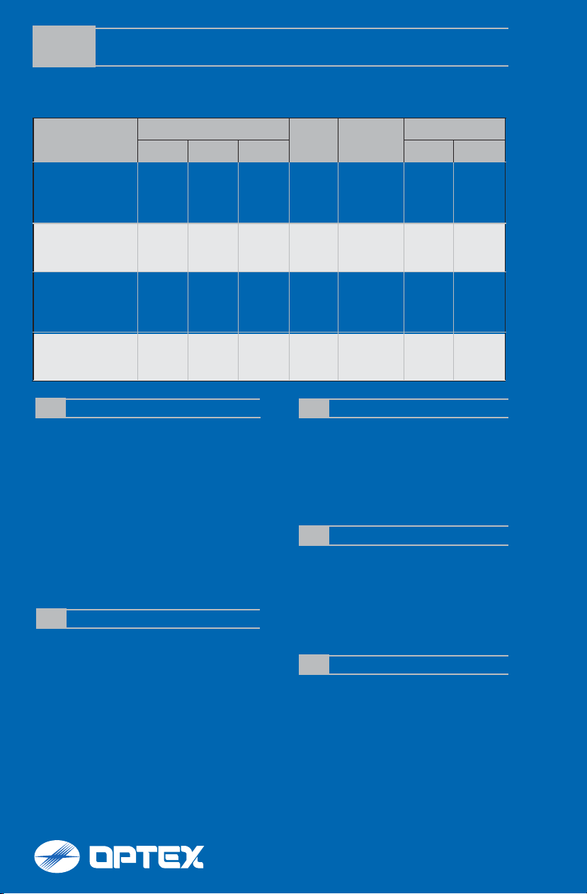
PROGRAMMING GUIDE
Set up “FITLINK” according to location as desired. Below are zone configurations for typical location types. For
specific panel types and programming instructions for your specific control panel, refer to installation instructions.
Location
Alarm Output Report to CMS
Disarm Away Stay Alarm Trouble
Panel
Event
Chime
Front Porch;
Backyard Carport;
Gate Entrance;
No
No
No
Yes
Toggle
On or Off
Deck
Crawl Space;
Basement;
Storage Shed;
No
Instant
Alarm
Instant
Alarm
Yes
On during
disarm
Garage or
Sliding Glass Door;
Screened in Porch;
No
Entry
delay 2
Entry
delay 2
Yes
On during
disarm
Sunroom
Driveway;
Sidewalk;
No
No
No
No
Toggle
On or Off
Public Areas
ENROLLING HONEYWELL ENROLLING INTERLOGIX
1. While in program mode, press *56 to enter Zone
Programming Menu Mode.
2. Select 0 or 1 to determine if you will “confirm” the sensor
after learning it.
3. Enter the zone number that you wish to program (or 00 to
exit zone programming). Press [*] to continue.
4. A summary display appears, press [*] to continue.
5. Enter “Zone Type” according to table found in Installation
Instruction.
6. Enter “Partition No.”
7. Enter “Report codes” according to table.
8. Enter “Input Type” to “3” = RF (supervised RF transmitter).
9. Learn or input transmitters serial number. (To learn
FITLINK, trip the tamper three times.)
10. Change “Loop Number” to 1.
ENROLLING 2GIG
1. Select “Wireless Zone #” (01 to 48).
2. Select “Sensor Type” from following:
(23) No Response Type, (03) Perimeter, (02) Exit/Entry 2
3. Select “Sensor Equipment Code” as “[0000] Other or
[0609] Existing Motion Detector”.
4. Select “Sensor Other Equip code as “[0]” (this menu only
appears if [0000] Other was selected in the previous menu.
5. At the “Sensor Serial Number” menu, press shift, then
press Learn, and then trip detector tamper switch.
6. Select “Equipment Age” as “New”.
7. Select “Loop Number ” as “Loop 1”.
8. Select “Dialer Delay” as “Enabled”.
9. Edit “Voice Descriptor” according to location.
10. Select “Sensor Reports” according to above table.
11. Select “Sensor Supervised” to “Enabled”.
12. Select the desired chime.
1. Put control panel in learn sensor mode.
2. Push tamper switch to enroll FITLINK.
3. Depending on panel type, select “Sensor Number”,
“Sensor group”, Sensor Name, and/or partition. Refer to your
control panel RF programming guide for specific details.
OPTEX recommendations can be found in the FitLink manual.
4. Press save to save the changes.
ENROLLING DSC
1. Put control panel in learn sensor mode.
2. Push tamper switch to enroll FITLINK.
3. Press [*] key to confirm ID.
4. Enter [zone #].
5. Enter [zone type]
6. Enter “Loop Number” 1.
7. Set “Zone Types” and “Zone Attributes”
ENROLLING QOLSYS
1. Enter Settings Menu and select "Installation".
2. Select "Security Sensors" and then select "Auto Learn
Sensor".
3. Trip the tamper to enroll within 2min.
4. Panel will chime and display the sensor's code. Select OK to
confirm.
5. Set "Sensor Type" to "Motion".
6. Set "Sensor Name" to the correct name from the list.
7. Set "Chime Type" to your preferred type.
8. Set “Sensor Group” according to table found in Installation
Instruction.
9. Select "Add New" to complete.
For programming technical support: 877-260-5578
No
Yes
Yes
No
For OPTEX support: 800-966-7839
Yes
Yes
Yes
Yes
support@optexamerica.com
www.optexamerica.com
 Loading...