

Page 1

N219
CONTENTS
1 INTRODUCTION
1-1 BEFORE INSTALLATION ................2
1-2 PARTS IDENTIFICATION ................3
1-3 DETECTION AREA..........................4
2 INSTALLATION
2-1 WIRING DIAGRAM..........................4
2-2 TRANSMITTER PREPARATION .....5
2-3 BEFORE WALL MOUNTING ...........6
2-4 STACKING METHOD ......................7
2-5 SIDE-BY-SIDE AND
TOP-TO-BOTTOM METHOD ........11
3 WALK TEST
3-1 WALK TEST ...................................13
4 DIP SWITCH SETTING
4-1 WALK TEST MODE .......................14
4-2 BATTERY SAVING TIMER ............14
4-3 ALARM & TROUBLE OUTPUT ......14
4-4 LED ................................................15
4-5 PIR SENSITIVITY ..........................15
4-6 ANTI-MASKING .............................15
5 OTHERS
5-1 WALL TAMPER (OPTION)
CONNECTION...............................16
5-2 LED LIGHT PATTERN ...................16
6 BATTERY
6-1 HOW TO REPLACE BATTERY .....17
6-2 BATTERY LIFE ..............................18
7 SPECIFICATIONS
7-1 SPECIFICATIONS .........................19
7-2 DIMENSIONS ................................20
FTN-R Battery operated model with 2 PIRs
FTN-RAM FTN-R
with anti-masking
Long battery life
Easy wiring by a connector
Multi fixing transmitter box
Compact design
190° adjustable bracket
Intelligent AND logic
Digital anti-masking (RAM model)
Wall tamper (option)
•
•
•
•
•
•
•
•
N
O.59-1646-0 091201
INSTALLATION INSTRUCTIONS
Compact outdoor
detector
Compact outdoor
detector
fit series
fit series
- 1 -
Page 2
1
INTRODUCTION
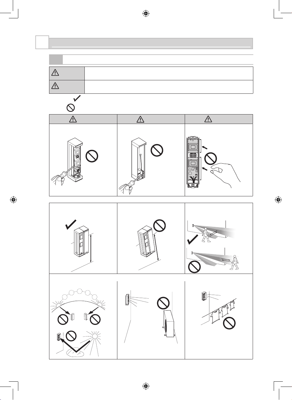
1-1
BEFORE INSTALLATION
Warning
Failure to follow the instructions provided with this indication and improper
handling may cause death or serious injury.
Caution
Failure to follow the instructions provided with this indication and improper
handling may cause injury and/or property damage.
The check
mark indicates recommendation.
The nix sign indicates prohibition.
Warning
Caution Caution
Do not remove the PCB. Do not remove the separate box
tamper.
Do
not touch the PCB except for the
DIP switch.
ON
1 2 3 4 5 6
ON
1 2 3 4 5 6
Mounting height. Keep the detector parallel to the
ground.
Consider the direction a person is
approaching from, as well as the
detection area.
Install the detector in a place where it is free from false alarm factors. For example:
Sunlight and reflection• Heat source• Objects moving in the wind •
0.8 – 1.2 m
(2'7
" – 3'11")
Parallel
Tilt
- 2 -
Page 3
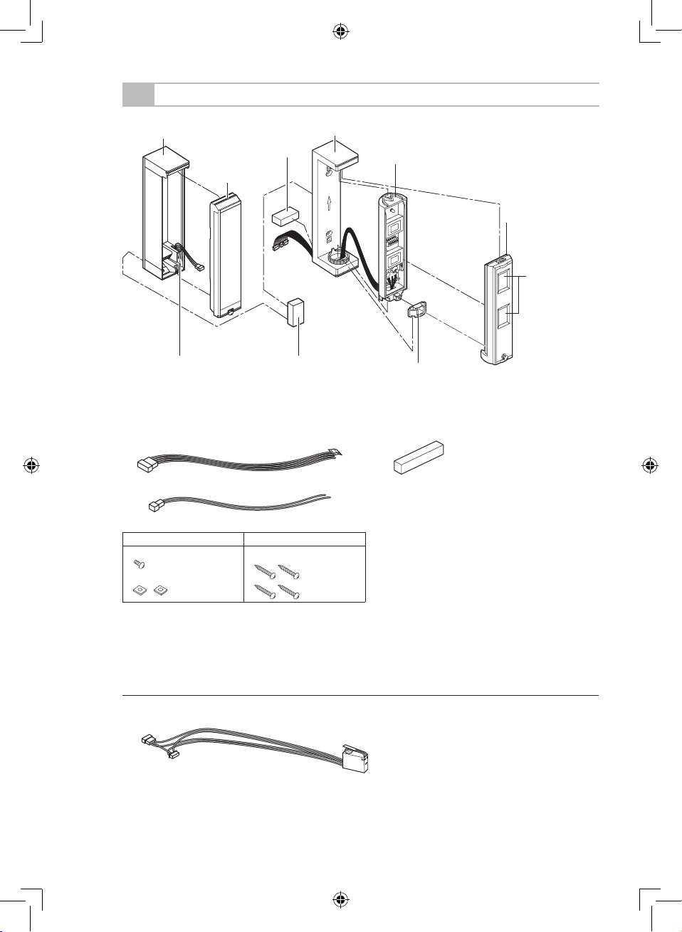
Separate box
Separate box tamper
Main unit
Bracket
Fixture
Main
unit cover
Lens
1-2
PARTS IDENTIFICATION
Connector for POWER and ALARM
Connector for TROUBLE
Screw kit
For joint For wall mounting
Screw (M3 × 10 mm)
Plate nut
Screw (3 × 20 mm)
Note>>
Transmitter and battery are not included.
-Optional accessories
Wall tamper (WRS-03)
•
Separate box cover
Sponge
Sponge
Sponge for transmitter
- 3 -
Page 4
0' 5' 10' 15'
0.8
0
(m)
1.0
1.2
2'7"
0'
(ft.)
3'3"
3'11"
10 2 3 4 5
(m)
(ft.)
0' 5' 10' 15'
0.8
0
(m)
1.0
1.2
10 2 3 4 5
(m)
2'7"
0'
(ft.)
3'3"
3'11"
(ft.)
0
10
0'0'5'
5'
5'
10'
10'
10'
15'
15'
15'
2 3 4 5
1
1
1
2
3
4
5
(m)
(ft.)
(ft.)
(m)
2
4
5
3
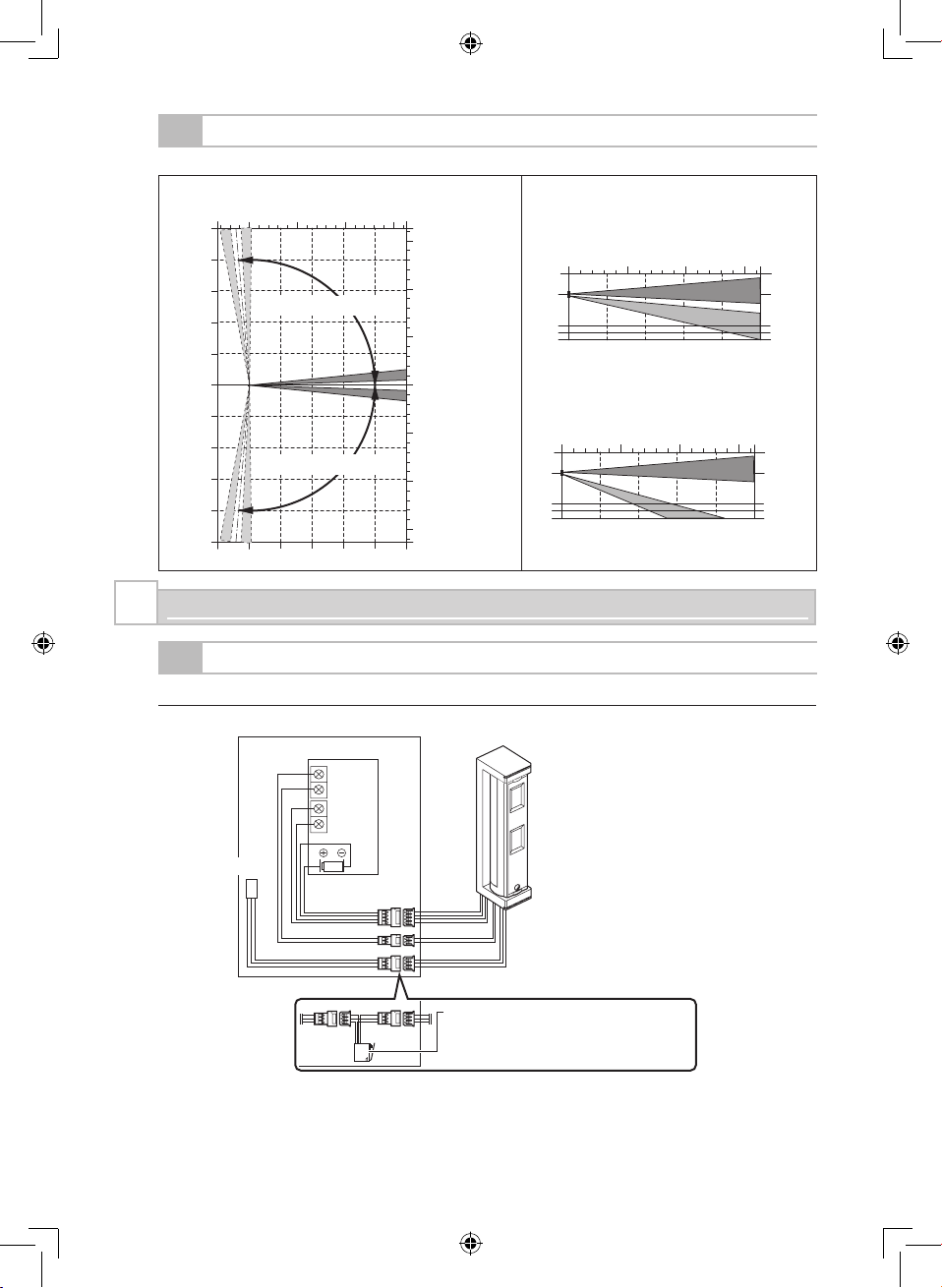
Separate box tamper
Trouble
Alarm
Wall tamper (option)
*For wall tamper wiring (option), refer to page
16.
Separate
box
Main unit
Transmitter
1-3
DETECTION AREA
Top view Side view
2 m detection length
5 m detection length
Adjustable range: 95° (by 5° pitch)
Adjustable range: 95° (by 5° pitch)
2
INSTALLATION
2-1
WIRING DIAGRAM
-Overall wiring diagram
Notes>>
The battery in the transmitter is shared with the detector.
Connection for TROUBLE is used when monitoring for Tamper and Anti Mask.
•
•
- 4 -
Page 5
35 (1.38")
130 (5.12")
30 (1.18")
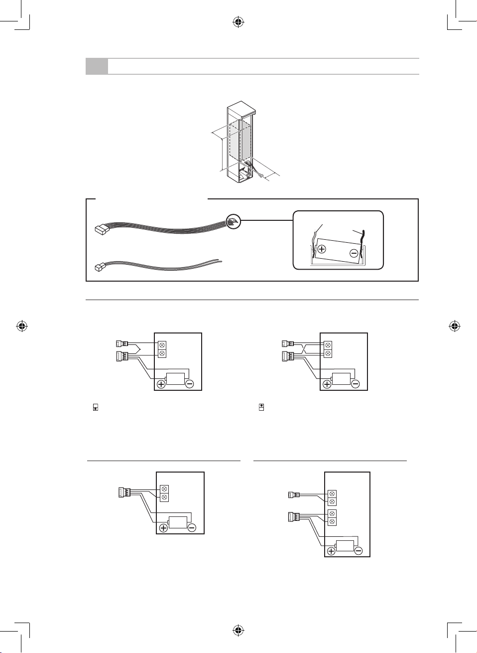
2-2
TRANSMITTER PREPARATION
The transmitter used should have the internal dimensions of H 130 × W 30 × D 35 mm.
(H 5.12" × W 1.18" × D 1.38")
- When monitoring ALARM and TROUBLE using the transmitter with 1 external input
External input is N.C. External input is N.O.
3
... DIP switch 3: OFF (N.C.)
3
... DIP switch 3: ON (N.O.)
-To monitor only the ALARM using a
transmitter with 1 external input
-To monitor the ALARM and TROUBLE
using a transmitter with 2 external inputs
Connectors to be used
Connector for POWER and ALARM
Connector for TROUBLE
Red
Black
How
to position a battery
Connector for POWER
and ALARM
Connector for
TROUBLE
Connector
for
POWER and ALARM
N.C.
N.O.
Unit: mm (inch)
- 5 -
Page 6
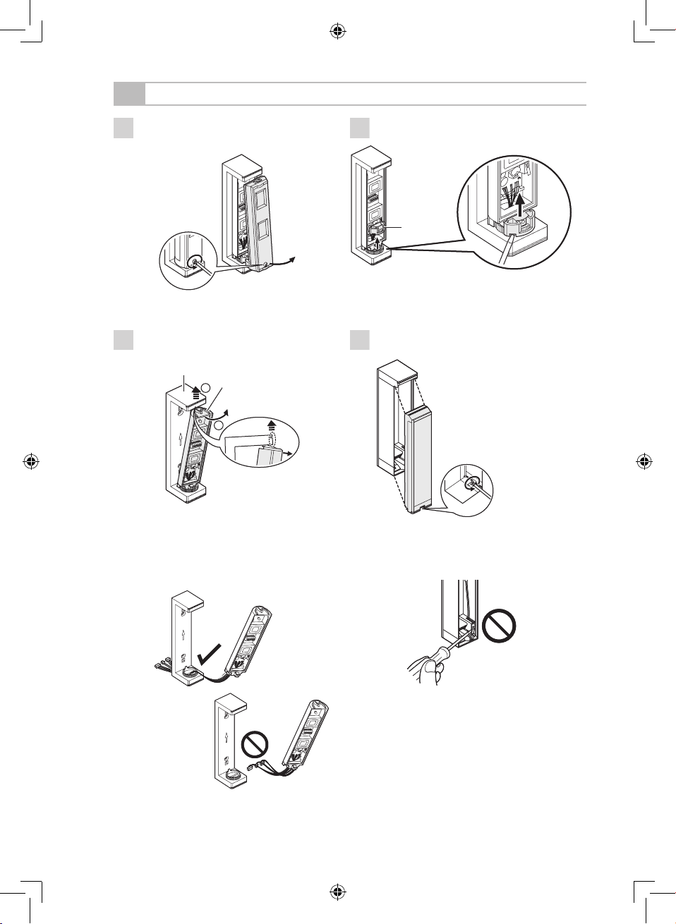
3
Hold the top of the bracket and
remove the main unit.
Note>>
Be sure to keep connectors installed
through the bottom part of bracket after
main unit is removed.
•
Bracket
Main unit
2
1
Bracket
Main unit
2
1
2-3
BEFORE WALL MOUNTING
1
Open the main unit cover.
2
Remove the fixture.
FixtureFixture
4
Open the separate box.
Note>>
Do not remove the separate box
tamper.
•
- 6 -
Page 7

5
Select the mounting method.
Stacking method
(Page 7)
Side-by-side method
(Page 11)
Top-to-bottom method
(Page 11)
Note>>
Be sure to mount the main
unit on the top.
•
2-4
STACKING METHOD
For the side-by-side method and the top-to-bottom method, refer to page 11.
6
Open the knockout.
Separate box
Separate box cover
Joint screw
knockout
W
all mounting
knockout
W
all mounting
knockout
Wiring knockout
Joint screw
knockout
Separate box
Separate box cover
Joint screw
knockout
W
all mounting
knockout
W
all mounting
knockout
Wiring knockout
Joint screw
knockout
7
Pull the connectors through the wiring
knockout.
- 7 -
Page 8

8
Attach the separate box cover and the bracket.
Notes>>
Be careful not to attach separate box cover upside down.
Be careful not to pinch wires.
•
•
Screw (3 × 10 mm)
Screw (3 × 10 mm)
Sponge
Plate
nut
Wiring
Sponge
Plate nut
Double-sided tape for
temporary fixing
Screw (3 × 10 mm)
Screw (3 × 10 mm)
Sponge
Plate
nut
Wiring
Sponge
Plate nut
Double-sided tape for
temporary fixing
9
Hold the top part of the bracket and
mount the main unit.
1
3
2
1
3
2
10
Mount the separate box on the wall.
Screw (3 × 20 mm)
Screw (3 × 20 mm)
Mounting height:
0.8 – 1.2 m (2'7" – 3'11")
Screw (3 × 20 mm)
Screw (3 × 20 mm)
Mounting height:
0.8 – 1.2 m (2'7" – 3'11")
100 mm
(3.94")
- 8 -
Page 9

13
Determine the horizontal detection
angle and attach the fixture.
Note>>
To make adjustments, remove the
fixture.
•
Angle pitch: 5°
95°
95°
Angle pitch: 5°
95°
95°
Note>>
Check that the fixture and bracket
engage correctly.
•
Note>>
Check that the fixture and bracket
engage correctly.
•
11
Connect the connectors.
Separate box side
Main unit side
Red
Black
White
Yellow
Red:
Power input (+)
Black: Power input (-)
White: Alarm
Yellow: Alarm
Green: Trouble
Blue:
Trouble
Brown: Tamper
Orange: Tamper
Grey:
Tamper
Green
Blue
Brown
Orange
Grey
Separate box side
Main unit side
Red
Black
White
Yellow
Red:
Power input (+)
Black: Power input (-)
White: Alarm
Yellow: Alarm
Green: Trouble
Blue:
Trouble
Brown: Tamper
Orange: Tamper
Grey:
Tamper
Green
Blue
Brown
Orange
Grey
Notes>>
The tamper output is not exclusive. The
Anti-masking and Tamper circuits share
the Trouble output.
For the wall tamper wiring connection
(option), refer to page 16.
To detect cutoff of tamper
input wires (3 wire
line) as shown in the
illustration, cut the orange
jumper wire provided for
purpose of detection.
In
this case, be sure to
use the connector of the separate box
tamper. Otherwise, the trouble output
will remain on.
•
•
•
12
Install the transmitter and attach the
separate box cover.
Note>>
Please use the sponge for transmitter
when needed.
•
1
2
3
Transmitter
1
2
3
Transmitter
- 9 -
Page 10

14
Determine the detection length. (2 m or 5 m)
If 2 m is required, rotate the lower lens
180 degrees.
Note>>
Do not remove the upper lens.•
5 m detection length
(Factory default)
2 m detection length
Side view
0' 5' 10' 15'
0.8
0
(m)
1.0
1.2
2'7"
0'
(ft.)
3'3"
3'11"
10 2 3 4 5
(m)
(ft.)
0' 5' 10' 15'
2'7"
0'
(ft.)
3'3"
3'11"
0.8
0
(m)
1.0
1.2
(ft.)
10 2 3 4 5
(m)
Side view
15
Attach the main unit cover.
Note>>
To prepare for walk test, check that DIP
switch 1 (WALK TEST MODE) is set to
“ON (TEST)” before attaching main unit
cover.
•
16
Perform walk test.
For details, refer to page 13.
17
After walk test is complete, set DIP
switch 1 (WALK TEST MODE) from
“ON” to “OFF”.
Note>>
The battery life will be shortened unless
the DIP switch 1 is set to “OFF”.
•
- 10 -
Page 11

6
Open the knockout.
Wiring knockout
(For side-by-side method)
Main unit
(Back
surface)
Wiring knockout
(For top-to-bottom
method)
Separate box
(Back surface)
Wiring knockout
(For side-by-side method)
Main unit
(Back
surface)
Wiring knockout
(For top-to-bottom
method)
Separate box
(Back surface)
Separate box
Wall mounting
knockout
W
all mounting
knockout
Wiring
knockout
Separate box
Wall mounting
knockout
W
all mounting
knockout
Wiring
knockout
2-5
SIDE-BY-SIDE AND TOP-TO-BOTTOM METHOD
For the stacking method, refer to page 7.
7
Pull the wire connectors through
wiring knockout.
8
Mount the bracket and the separate box to the wall.
Wiring
Side-by-side
method
Screw (3 × 20 mm)
Screw (3 × 20 mm)
Top-to-bottom
method
Double-
sided tape
Sponge Sponge
Mounting
height:
0.8
– 1.2 m
(2'7" – 3'11")
83.5 mm
(3.29")
Note>>
Be careful not to pinch wires.•
Wiring
Side-by-side
method
Screw (3 × 20 mm)
Screw (3 × 20 mm)
Top-to-bottom
method
Doublesided tape
Sponge Sponge
Mounting
height:
0.8
– 1.2 m
(2'7" – 3'11")
83.5 mm
(3.29")
Note>>
Be careful not to pinch wires.•
10 0 mm
(3.94")
Double-sided tape
- 11 -
Page 12

9
Hold the top part of the bracket and
mount the main unit.
1
3
2
1
3
2
10
Connect the connectors.
Notes>>
The tamper output is not exclusive. The
Anti-masking and Tamper circuits share
the Trouble output.
For the wall tamper wiring connection
(option), refer to page 16.
To detect cutoff tamper
input wires (3 wire
line) as shown in the
illustration, cut the orange
jumper wire provided for
purpose of detection.
In
this case, be sure to
use the connector of the separate box
tamper. Otherwise, the trouble output
will remain on.
•
•
•
Separate box side
Main unit side
Red
Black
White
Yellow
Red:
Power input (+)
Black: Power input (-)
White: Alarm
Yellow: Alarm
Green: Trouble
Blue:
Trouble
Brown: Tamper
Orange: Tamper
Grey:
Tamper
Green
Blue
Brown
Orange
Grey
Separate box side
Main unit side
Red
Black
White
Yellow
Red:
Power input (+)
Black: Power input (-)
White: Alarm
Yellow: Alarm
Green: Trouble
Blue:
Trouble
Brown: Tamper
Orange: Tamper
Grey:
Tamper
Green
Blue
Brown
Orange
Grey
11
Install the transmitter and attach the
separate box cover.
Transmitter
1
2
3
Transmitter
1
2
3
12
For the subsequent procedure, refer
to steps 13 to 17 (page 9 to 10).
- 12 -
Page 13

1
Set the DIP switch 1 (WALK TEST
MODE) to “ON (TEST)”.
Note>>
The switch is set to “ON (TEST)” by
factory default.
•
ON
1 2 3 4 5 6
ON
1 2 3 4 5 6
ON
1 2 3 4 5 6
DIP switch
ON
1 2 3 4 5 6
ON
1 2 3 4 5 6
ON
1 2 3 4 5 6
DIP switch
3
Set the DIP switch 1 (WALK TEST
MODE) to “OFF (NORM)”.
Notes>>
The battery life will be shortened unless
the DIP switch 1 is set to “OFF”.
To use the LED in normal operating
condition, set the DIP switch 4 to “ON”.
•
•
ON
1 2 3 4 5 6
ON
1 2 3 4 5 6
ON
1 2 3 4 5 6
DIP switch
ON
1 2 3 4 5 6
ON
1 2 3 4 5 6
ON
1 2 3 4 5 6
DIP switch
3-1
WALK TEST
3
WALK TEST
2
Check that LED lights for 2 seconds
when the intended object is detected.
Detected
Not detected
- 13 -
Page 14

Note>>
The detector will not generate
alarms at intervals shorter
than the specified time.
•
4-1
WALK TEST MODE
DIP switch 1
FTN-R
FTN-RAM
ON
1 2 3 4 5 6
TEST
NORM
Position Function
TEST
(Factory
default)
The LED lights irrespective of the DIP
switch 4 (LED) setting.
The DIP switch 2 (BATTERY SAVING
TIMER) setting is inactive.
•
•
NORM
The
LED lights depending on the DIP
switch 4 (LED) setting.
The DIP switch 2 (BATTERY SAVING
TIMER) setting is active.
•
•
4-2
BATTERY SAVING TIMER
DIP switch 2
FTN-R
FTN-RAM
ON
1 2 3 4 5 6
5S
120S
Position Function
5S 5
sec.
120S
(Factory
default)
120 sec.
4-3
ALARM & TROUBLE OUTPUT
DIP switch 3
FTN-R
FTN-RAM
ON
1 2 3 4 5 6
N.O.
N.C.
Position Function
N.O. N.O.
output
N.C.
(Factory
default)
N.C. output
ON
1 2 3 4 5 6
ON
1 2 3 4 5 6
ON
1 2 3 4 5 6
ON
1 2 3 4 5 6
ON
1 2 3 4 5 6
ON
1 2 3 4 5 6
ON
1 2 3 4 5 6
ON
1 2 3 4 5 6
ON
1 2 3 4 5 6
ON
1 2 3 4 5 6
●: Factory default
DIP switch
1 WALK TEST MODE
2 BATTERY SAVING TIMER
3 ALARM & TROUBLE OUTPUT
4 LED
5 PIR SENSITIVITY
6 ANTI-MASKING
Do not touch the
PCB except for the
DIP switch.
4
DIP SWITCH SETTING
- 14 -
Page 15

4-4
LED
DIP switch 4
FTN-R
FTN-RAM
ON
1 2 3 4 5 6
ON
OFF
Position Function
ON LED
ON
OFF
(Factory
default)
LED OFF
Note>>
If the LED lights, check the DIP
switch 1 (WALK TEST MODE)
setting.
•
4-5
PIR SENSITIVITY
DIP switch 5
FTN-R
FTN-RAM
ON
1 2 3 4 5 6
Position Function
STD
(Factory
default)
Normal sensitivity
LOW Low
sensitivity
4-6
ANTI-MASKING
DIP switch 6
FTN-R
FTN-RAM
ON
1 2 3 4 5 6
Position Function
ON
(Factory
default)
ANTI-MASKING ON
OFF ANTI-MASKING
OFF
-ANTI-MASKING function
When
masking condition continues more than 3 minutes, TROUBLE will be generated.
TROUBLE is generated after 20 seconds under the anti-masking test mode.
STD
LOW
ON
OFF
Teaching mode starts when both the separate box cover and the main unit cover are
attached.
Please
be careful not to leave any object within 1 m from the unit.
ANTI-MASKING test mode
The trouble is output after 20 seconds.
Normal mode
The trouble is output after 3 minutes.
10 minutes1 minute
Teaching
- 15 -
Page 16

5-1
WALL TAMPER (OPTION) CONNECTION
Connect the tamper connector as shown below when connecting a wall tamper (option).
Mounting position
Stacking method Side-by-side method and top-to-bottom method
Separate box
Bracket
5
OTHERS
Separate box side
Main unit side
Wall tamper (option)
WRS-03
Sponge
Sponge
5-2
LED LIGHT PATTERN
The following explains the LED light pattern.
Detector condition LED indicator
Warm-up
Note>>
The LED blinks even if the DIP
switch 4 (LED) is set to “OFF”.
•
Blinks for approx. 120 seconds.
Alarm
Lights for 2 seconds.
Masking detection
(FTN-RAM only)
Blinks 3 times and then repeats.
LED
Blink Light OFF
- 16 -
Page 17

1
Open the separate box, and
disconnect the transmitter connector.
(It is not necessary for the main unit
to be opened.)
6
BATTERY
The detector shares the battery with the transmitter. Check that the 2.5 to 10.0 V power battery is
used for the transmitter.
6-1
HOW TO REPLACE BATTERY
Stacking method
Side-by-side method and
top-to-bottom method
Separate box
Separate
box cover
Separate box
Separate box
cover
Black
Red
3
2
Replace the battery.
3
Connect the connector, and close the
separate box.
Note>>
Check that the warm-up period is
started.
•
- 17 -
Page 18

6-2
BATTERY LIFE
The values indicated are only for reference on condition that the detector is exceptionally
operated by the sole battery.
It is impossible to indicate the battery life under the normal operation as the battery in the
transmitter is shared with the detector.
Interval 120 sec Interval 5 sec
CR123A (3 V, 1300 mAh) Approx. 6 years Approx. 5 years
CR2 (3 V, 750 mAh) Approx. 4 years Approx. 3 years
1/2AA (3.6 V, 1000 mAh) Approx. 5 years Approx. 4 years
Note>>
Data shown here is when the LED is off, AM is on. Battery life becomes shorter when the
LED is on.
•
- 18 -
Page 19

7
SPECIFICATIONS
7-1
SPECIFICATIONS
Model FTN-R FTN-RAM
Detection method Passive infrared
PIR coverage 5 × 1 m (16'5" × 3'3")
Detection length limit 2 m, 5 m (6'7", 16'5")
Detectable speed 0.3 – 1.5 m/s (1' – 4'11"/s)
Sensitivity 2.0°C
(at 0.6 m/s) (3.6°F (at 2'/s))
Operation voltage 2.5 – 10 V DC
Power input 3 – 9 V DC (Lithium or Alkali Battery)
Current draw
9 μA (at stand-by)/3 mA
(max.)
(at 3 V DC)
10 μA (at stand-by)/3 mA
(max.) (at 3 V DC)
Alarm period 2.0 ±1.0 sec.
Warm-up period Approx. 120 sec. (LED blinks)
Alarm output
N.C./N.O. Selectable-Solid State Switch 10 V DC 0.01 A
(max.)
T
rouble output
N.C./N.O. Selectable-Solid State Switch 10 V DC 0.01 A
(max.)
LED
indicator
Enable:
During DIP switch 1 (WALK TEST MODE) or
DIP switch 4 (LED) ON
Disable: During normal operation
Light/Blink: Warm-up, alarm, masking detection
RF Interference No alarm 10 V/m
Operation temperature -20 – +60°C (-4 – +140°F)
Environment humidity 95% max.
Weatherproof IP55
Mounting W
all (Outdoor, Indoor)
Mounting height 0.8 – 1.2 m (2'7" – 3'11")
Weight 190
g (6.7 oz.)
Accessories
Connector
for POWER and ALARM,
connector
for TROUBLE, plate nut × 2,
screw
(M3 × 10 mm) × 2, screw (3 × 20 mm) × 4,
sponge
for transmitter
*Specifications and design are subject to change without prior notice.
- 19 -
Page 20

7-2
DIMENSIONS
Unit: mm (inch)
Unit: mm (inch)
35 (1.38") 42.5 (1.67") 35 (1.38") 42.5 (1.67")
155 (6.10")
155 (6.10")
Note>>
These units are designed to detect an intruder and activate an alarm control panel. Being
only a part of a complete system, we cannot accept responsibility for any damages or other
consequences resulting from an intrusion. These products confirm to the EMC Directive
2004/108/EC.
•
OPTEX INCORPORATED (USA)
TEL:+1-909-993-5770
Tech:(800)966-7839
URL:http://www.optexamerica.com/
OPTEX KOREA CO., LTD. (KOREA)
TEL:+82-2-719-5971
URL:http://www.optexkorea.com/
OPTEX SECURITY Sp. z o. o. (POLAND)
TEL:+48-22-598-06-55
URL:http://www.optex.com.pl/
OPTEX (DONGGUAN) CO., LTD.
SHENZHEN OFFICE (CHINA)
TEL:+86-755-33302950
URL:http://www.optexchina.com/
OPTEX CO., LTD. (JAPAN)
(ISO 9001 Certified)
(ISO 14001 Certified)
5-8-12 Ogoto Otsu
Shiga 520-0101
JAPAN
TEL:+81-77-579-8670
FAX:+81-77-579-8190
URL:http://www.optex.co.jp/e/
OPTEX (EUROPE) LTD. (UK)
TEL:+44-1628-631000
URL:http://www.optexeurope.com/
OPTEX SECURITY SAS (FRANCE)
TEL:+33-437-55-50-50
URL:http://www.optex-security.com/
- 20 -
 Loading...