

Page 1

CX-702 , CX-702V
PASSIVE INFRARED DETECTOR
INSTALLATION INSTRUCTIONS
14
PASSIVE INFRARED DETECTOR
CX-702 , CX-702V
INSTALLATION HINTS
1
DETECTION AREA
2
SPECIFICATIONS
9
TROUBLE SHOOTING
8
EGNAR GNOLELGNA EDIW
207-XCledoM
Current draw
V207-XCledoM
Current draw
See Section 7-3.
Alarm memory
D.L. terminal
No.59-0951-6 1602-22
UL No 59-0951-4 0904-30
Avoid direct sunlight.
Avoid vapor or high
humidity that can
cause condensation.
Do not install outdoors.
Avoid Curtain,Screen,etc.
blocking detection area.
1
4
5
3
6
7
8
2
This symbol indicates prohibition.
• This unit is designed to detect movement of an intruder and activat e an
alarm control panel.
• Being only a part of a complete system, we c annot accept responsibility
for any damages or other consequences resulting from an intrusion.
Note>>
*The CX-702 is UL Listed per UL639,Intrusion-Detection Units.
*The CX-702V has not been investigated by UL.
OPTION
CA-1W : Wall Mount Bracket : adjustable ±45° (Horizontally),
0 to 20° (Vertically downwards)
CA-2C : Ceiling Bracket : adjustable ±45° (Horizontally),
0 to 20° (Vertically downwards)
Avoid mounting detector where
movement of Fans or Air
Conditioning Fans can be
detected.
Never repair or modify
product. It may cause
accident, fire hazard or
electric shock.
Mount securely.
A falling product
may cause injury.
When damage has occured to
the product, i.e. water logged,
abnormal things inside product,
overheating or smoking, strange
smells etc., immediately stop
using product and contact your
supplier. Otherwise, continued
use in such condition may cause
electric shock or fire hazard.
WARNING
WARNING
CAUTION
Model
CX-702 / CX-702V
evissaPdohtem noitceteD
Infrared
68 zone
1.5 to 3.6 m (5 to 12 ft.)
Wide Angle 85° wide
21 m × 21 m
(70 ft. × 70 ft.)
0.3 to 1.5 m / sec. (1 to 5 ft. / sec.)
Alarm condition
Approx. 2.5 sec.
N.C., 28 V DC 0.2 A (max.)
N.C., Opens when cover removed.
28 V DC 0.1 A (max.)
Approx. 20 sec. 2 or 4
Approx. 1 min.
9.5 to 16 V DC
200 g (7.0 oz)
-20°C to +50°C (-4°F to +122°F)
95 % (max.)
No Alarm 30 V / m
Detection zones
Mounting height
1.6°C at 0.6 m / sec., 2.4 m mounting height
(3°F at 2 ft. / sec., 8 ft. mounting height)
Sensitivity
Coverage
Detectable speed
LED indicator
Alarm period
Alarm output
Tamper switch
Pulse count
Warm up period
Power input
Weight
Operating temperature
Environment humidity
RF interference
Long Range
45 m × 2.4 m
(150 ft. × 8 ft.)
PROBLEM
LED does not light.
LED lights even
though no person
within area.
LED lights but
signal is not sent.
LED continues to light.
YDEMERESUAC ELBABORP
Incorrect power supply voltage. (disconnection, or low voltage)
Improper detection area.
LED switch is OFF.
Improper polarity to detector.
Moving object within area. (curtain,wall hanging, etc.)
Temperature of object within area changing rapidly.
(heater, air conditioning, etc.)
Relay contact is stuck of damaged due to overloading.
Faulty Wiring.
Poor connection of alarm memory.
Wrong control voltage from panel.
Correct supply voltage to 9.5 to 16 V DC. See Section 5.
See Section 2.
Turn on the switch.
Switch positive and negative at terminal.
Remove the souces from the detection area.
Remove object from the detection area.
Check load of output. The unit needs repair or replacement.
Wire correctly.
Reconnect wire.
Must be 0 to 1 V DC (grounded) See Section 7-3.
Dimensions
mm (inch)
140 (5.51)
69 (2.72)
SIDE VIEW
A
0
TOP VIEW
0 5 10 15 20 21 m
30
10
5
0
5
10m
20
10
0
10
20
10 20 30 40 50 60 70ft.
30ft.
0 5 10 15 20 21
1.5
2.4 m
m
0 10 20 30 40 50 60 70ft.
85ft.
0 5 10 15 20 25 30 35 40 45
1.5
2.4 m
m
0 10 20 30 40 50 60 70 80 90 100 110 120 130 140 150 ft.
85ft.
B
0 5 10 15 20 25 30 35 40 45
1.5
2.4
3.6 m
m
0 10 20 30 40 50 60 70 80 90 100 110 120 130 140 150 ft.
12
8
5
ft.
C
A
B
C
0 5 10 15 20 25 30 35 40 45
1.5
2.4
3.6 m
m
10 20 30 40 50 60 70 80 90 100 110 120 130 140 150 ft.
12
8
5
ft.
TOP VIEW
SIDE VIEW
0 5 10 15 20 25 30 35 40 45mm
0 10 20 30 40 50 60 70 80 90 100 110 120 130 140 150 ft.
5
0
5
2
1
0
1
2
ft.
120251010
1.5
2.4
3.6 m
m
0 10 20 30 40 50 60 70ft.
12
8
5
ft.
0 5 10 15 20 21
1.5
2.4
3.6 m
m
0 10 20 30 40 50 60 70ft.
12
8
5
ft.
5
00
FEATURES
● Dual Purpose Lens:Selectable ”WIDE ANGLE” and “LONG RANGE” detection patterns
● Double Conductive Shielding of the pyroelectric element Extremely High Light and RFI
Immunity (Patent listed)
● Multifocus Optics Design (Patent listed)
● LED On / Off Switch
● Sealed Optics
● Easy Installation
● Alarm Memory (CX-702V Only)
● LED Remote Control Terminal (CX-702V Only)
**ATTENTION**
The specified detection area can be achieved by mounting the unit at a height of 2.4 m (8 ft.).
Mounting at a lower or higher height may reduce the area of coverage
OPTEX CO., LTD. (JAPAN)
URL: http://www.optex.net
100 (3.94)
Manufacturer:
OPTEX CO., LTD.
5-8-12 Ogoto, Otsu, Shiga, 520-0101 JAPAN
Authorised representative in Europe:
OPTEX (EUROPE) LTD. / EMEA HEADQUARTERS
Marandaz House 1 Cordwallis Park, Clivemont Road,
Maidenhead, Berkshire, SL6 7BU U.K.
22 zones
8 mA (normal) / 11 mA (max.) at 12 V DC
8 mA (normal) / 16 mA (max.) at 12 V DC
See Section 7-1.
* Specifications and design are subject to change without prior notice.
OPTEX INC. (U.S.)
URL: http://www.optexameric a.com
OPTEX DO BR ASIL LTDA. (Brazil)
URL: http://www.optex.net/ br/es/sec
OPTEX (EUROPE) LTD. / EMEA H Q (U.K.)
URL: http://www.optex-europe.c om
OPTEX TECHNOLO GIES B.V. (The Nethe rlands)
URL: http://www.optex.eu
OPTEX SECURIT Y SAS (France)
URL: http://www.optex-secur ity.com
OPTEX SECURIT Y Sp.z o.o. (Poland)
URL: http://www.optex.com.pl
OPTEX PINNACLE I NDIA, PVT., LTD. (India)
URL: http://www.optex.net/ in/en
/sec
OPTEX KOREA CO.,LTD. (Korea)
URL: http://www.optexkorea.co m
OPTEX (DONGGUAN) CO., LTD.
SHANGHAI OFFI CE (China)
URL: http://www.optexchina.com
OPTEX (Thailand ) CO., LTD. (Thailand)
URL: http://www.optex.net/ th/th
Copyright (C) 2016 OP TEX CO.,LTD.
Page 2
3
2
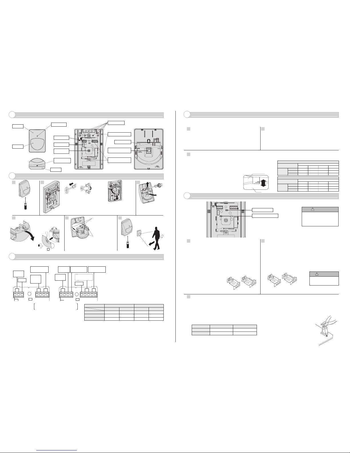
DESCRIPTION AND OPERATION
3
INSTALLATION
4
WIRING
5
ADJUSTMENTS FOR REQUIRED AREA PATTERN
6
FUNCTIONS
7
Loosen fastening screw and
remove cover.
Lead in wires through knockouts
along the wiring guide on the
rear side of base. Mount base
with supplied screws. When
using a bracket, check matching
knockout position before opening
mounting holes. Wire according
to Section 5.
When you remove the PCB,
push down on the hook under
PCB and remove it from its
base. Attachment of PCB is
the reverse of removal.
Remove the screw fixed the
lens holder (CX-702V Only),
open the cover's hook and
then lens cover can be
removed.
Power wires should not exceed the following lengths.
VOLTAGE
WIRE SIZE
AWG 22 (0.33 mm
2
)
12 V
V207-XC207-XC
14 V 12 V 14 V
520 m (1700 ft) 1130 m (3700 ft)
360 m (3700 ft)
770 m (2520 ft)
1220 m (4000 ft)
1960 m (6430 ft)
560 m (1830 ft)
900 m (2950 ft)
1780 m (5830 ft)
2850 m (9350 ft)
820 m (2690 ft)
1310 m (4290 ft)
AWG 20 (0.52 mm
2
)
AWG 18 (0.83 mm
2
)
1
2
1
3
3
The CX-702 is designed to provide ideal detection areas for different patterns ranging from 12 m (40 ft.) to 21 m (70 ft.) Wide Angle, and 24 m
(80 ft.) to 45 m (150 ft.) Long Range. The following adjustments will provide ideal detection areas for each of these requirements.
LED ON / OFF
2
PULSE COUNT
ALARM MEMORY ( CX-702V Only )
The Detection Mode can be switched to either “2” or “4” mode
depending on the environmental conditions of the installation.
2 : For normal applications.
4 : For use in hostile areas where there may be movement of small
animals or other objects such as fax machines or curtains.
When the “4” is selected, the detector’s sensitivity may seem sluggish. It is
therefore important to always conduct a walktest to ensure that the desired
coverage is given.
Operation
If the unit triggered during armed period, when the system is
disarmed, LED will remain lit to confirm that it reported an alarm.
· Alarm Memory will operate even when LED is switched OFF.
· Alarm Memory will not operate while system is disarmed.
· After Alarm Memory latches, Alarm Output and LED operate
normally during armed period.
Reset
Alarm Memory resets automatically
when system is re-armed.
Jumper Pin Switch
The Alarm LED indicator can be switched either “ON” or “OFF”.
D.L. terminal (CX-702V Only)
LED can be enabled or disabled remotely from control panel by
D.L. terminal.
1) Place Jumper Pin Switch in OFF position.
2) LED “ON” :
Connect DL terminal to common ground with
detector. (0 to 1 V DC, grounded)
LED “OFF” :
No Connection to the DL terminal.
(OPEN or +5 to 16 V DC)
Alarm Memory
This function is used to indicate if the detector was activated
while the panel was armed. It will cause the red LED on the
Detector to illuminate once the panel has been disarmed.
Compatible Control Panel is required for Alarm memory.
Connect A.M. terminal to Control Panel’s Control Voltage
Signal terminal (System Arming Status Voltage Output).
1
3
DETERMINE THE AREA PATTERN
2
SELECTING WIDE ANGLE OR LONG RANGE
DETECTION
VERTICAL ADJUSTMENT OF DETECTION AREA
1. Inverting the lens will select either the Wide Angle or Long Range detection patterns.
2. Please note markings “W (Wide Angle) ” and “L (Long Range) ”, on each side of lens.
3. For Wide Angle, “W” will be on top of lens.
4. For Long Range, “L” will be on top of lens.
1. Set the upper edge of the lens at either the “A”, “B” or “C” position.
2. The following chart illustrates the different position setting.
3. Confirm the detection area by conducting a walktest.
Before making adjustments, determine the pattern area,
detection range mounting height.
Adjust the vertical angle according to the desired detection
range and mounting height.
Cover
Lens
LED Indicator
Terminals
Tamper switch
Sensor
Do not touch.
Cover Fastening
Screw
Base
Wiring Knockout
Lens Holder
Corner mount Knockout
Double Conductive Shield
Do not touch.
Mounting Knockout
Pitch 83.5 mm (3.29 inch)
Remove lens holder carefully.
Select wide angle or long range
according to Section 6-2. (Note:
Factory default is WIDE ANGLE.)
Check to confirm that the lens is in the
desires position. Press down the lens
holder until it clicks into place along the
guide of cover. Fix the screw at the end.
Conduct a walktest and
make adjustments
(Section 7). Fit cover
using fastening screw.
4
5
6
Guides of Cover
Guides of Lens Holder
POSITIVE : Leave AM Jumper as it is.
NEGATIVE : Cut AM Jumper as shown.
AM Jumper
System armed
System Disarmed
OPEN or +5 to 16 V DC
0 to 1 V DC(grounded)
0 to 1 V DC(grounded)
OPEN or +5 to 16 V DC
POSITIVE NEGATIVE
CONTROL VOLTAGE SIGNAL
2
ON OFF
4
Do not use pulse count 4
for Long Range detection.
Always conduct a walktest after
changing the position of this
switch to ensure the detector is
still providing optimum coverage.
CAUTION
LED ON / OFF Switch
Pulse Count Selector (2 / 4)
W : WIDE ANGLE
DISTANCE
HEIGHT
1.8 (6)
2.4 (8)
3.6 (12)
12 (40) 15 (50) 18 (60) 21 (70)
BAAA
CCCC
CCCC
L : WIDE ANGLE
DISTANCE
HEIGHT
1.8 (6)
2.4 (8)
3.6 (12)
24 (80) 15 (100) 36 (120) 45 (150)
BBAA
CCCC
CCCC
m (ft.)
CAUTION
W
W
L
TAMPER
(N.C.)
ALARM
OUTPUT
(N.C.)
POWER INPUT
(9.5 to16 V DC)
SPARE
SPARE
TAMPER
(N.C.)
ALARM
OUTPUT(N.C.)
POWER INPUT
(9.5 to 16 V DC)
CX-702VCX-702
D.L.
(Disable LED)
ALARM
MEMORY
Connect tamper terminals to
a 24 hour s upervisory loop.
A
B
C
Lens Holder
Lens
● When using two or more units on one wire, the maximum length is obtained by dividing the maximum wire length listed above by the number of units
used.
●
UL requires CX-702 to be connected to a UL listed power supply capable of providing a nominal input of 12 V DC 11 mA (max.) and battery standby time
of 4 hours.
●
For UL Listed systems, do not connect field wiring more than 25 ft. to Alarm Memory, and DL terminals.
●
The equipment shall be installed in accordance with the National Electrical Code, NFPA 70.
 Loading...