

Optex THERMO-HUNTER BUILT-IN, CS-30TAC-HT, CS-30TAC, CS-40TAC-HT, CS-40TAC Instruction Manual
Page 1

THERMO-HUNTER BUILT-IN
CS-30TAC
,
CS-40TAC
CS-30TAC-HT
,
CS-40TAC-HT
Non-Contact Thermometer
Printed in JAPAN 1941-4 2013/09
Instruction Manual
OPTEX FA CO., LTD.
91 Chudoji-Awata-cho Shimogyo-ku Kyoto
600-8815 JAPAN
TEL: +81-75-325-1314 FAX: +81-75-325-2936
Page 2

2
Introduction
○ Please make sure the model you purchased is the one you specifi ed.
○ Please read the manual thoroughly before using the device for correct
usage.
○ After reading this manual, please retain it for future reference.
○ OPTEX is not liable for any incidental or consequential damages or losses
including losses of data or changes of measurement, arising from accident,
misuse or abnormal conditions of operation or handling.
Thank you very much for purchasing OPTEX products.
This device is a non-contact thermometer to convert the infrared energy emitted from the
surface of an object into temperature. This thermometer measures the surface temperature
of solid and liquid without contacting them. The temperature of gas cannot be measured by
this thermometer.
Contents
Introduction ................................................................................................ 2
Safe Usage ................................................................................................3
Warnings & Caution on Environment and Usage ......................................3
Specifi cations ............................................................................................4
External Dimensions/Parts Name..............................................................5
Wiring Diagram ..........................................................................................6
Mounting/Installation..................................................................................8
Field of View ..............................................................................................9
How to Use ..............................................................................................10
Function List ............................................................................................ 11
Setup of Functions...................................................................................12
BANK mode .......................................................................................12
DELY mode ........................................................................................12
TADJ mode ........................................................................................12
ASCL mode........................................................................................15
ALAM mode .......................................................................................16
TRIG mode ........................................................................................ 18
ECO mode .........................................................................................21
END mode ......................................................................................... 21
Troubleshooting ....................................................................................... 22
Maintenance ............................................................................................ 22
Page 3
3
This product is not a clinical thermometer and therefore, cannot be used for medical
purposes.
Use of controls or adjustments or performance of procedures other than those
specifi ed herein may result in hazardous radiation exposure.
Safe Usage
This instruction manual contains various warnings for your safety and proper usage to avoid
possible personal injury. Please be sure to heed the warnings and strictly follow safety
instructions.
This symbol signifies that improper usage may result in injuries or
damage.
Environmental Warnings - Warning - Caution
Usage Warnings - Warning - Caution
Caution
!
Caution
!
Caution
!
!
!
!
!
!
!
!
DO NOT USE THERMOMETER WHEN IT IS WET OR
SOAKED IN LIQUID.
Although the product is water-resistant, using it with water
drops on its lens or in wet conditions may cause incorrect
measurement.
AVOID MEASURING SHINY OBJECTS.
Shiny objects refl ect surrounding temperatures. Incorrect
measurement may occur although specifying the emissivity
rate can correct it.
DO NOT USE WITH NON-STANDARD VOLTAGE.
Using the unit out of 12 to 24 VDC range may result in
damage to the unit, shorts, fi res and injuries. In such cases,
immediately switch the unit off.
DO NOT TOUCH THE LENS.
Do not touch the lens with hard or sharp objects. Do not
insert foreign objects into the light receiving part. Otherwise
incorrect measurement will occur.
KEEP THE THERMOMETER AWAY FROM DIRECT
SUNLIGHT, DUST, HIGH TEMPERATURES AND HIGH
HUMIDITY DURING USE AND STORAGE.
This may cause irreparable damage or incorrect
measurement.
DO NOT DROP THIS THERMOMETER NOR GIVE
A STRONG IMPACT TO IT, WHICH MAY CAUSE
IRREPARABLE DAMAGE OR INCORRECT MEASUREMENT.
This may cause irreparable damage or incorrect measurement.
DO NOT LET THE THERMOMETER TOUCH THE OBJECT
THAT IS BEING MEASURED.
This product is a non-contact thermometer. Touching hightemperature object may cause deformation of the meter,
irreparable damage or incorrect measurement.
DO NOT BRING THE THERMOMETER CLOSE TO
ELECTRICALLY CHARGED OBJECTS.
This may cause irreparable damage or incorrect
measurement.
KEEP THE THERMOMETER AWAY FROM SUDDEN
CHANGE IN AMBIENT TEMPERATURE.
Sudden temperature change may cause incorrect
measurement. Start measurement when temperature has
become stable after leaving the meter for a while.
KEEP THE THERMOMETER AWAY FROM PRODUCTS
WHICH PRODUCE STRONG ELECTROMAGNETIC
WAVES. DO NOT USE IN AN ATMOSPHERE CONTAINING
CORROSIVE GASES OR EXPLOSIVE GASES.
This may cause irreparable damage or incorrect measurement.
Page 4

4
Accessories: Mounting nut (M12 × P1.0) × 2
Options: Black body tape, mounting fi tting, amplifi er protective case, changeable laser marker, air purge
collar, CF lens
* The specifi cations are subject to change without notice for product improvement.
Specifi cations
Model
CS-30TAC-HT CS-40TAC-HT
CS-30TAC CS-40TAC
Temperature range 0 °C to 1000 °C -40 °C to 500 °C
Area size
φ
30/500 mm
22:1
φ
40/500 mm
15:1
φ
30/500 mm
22:1
φ
40/500 mm
15:1
Optics Silicon lens(Water-repellent coat, Oil-repellent coat)
Detection element /
Wavelength
Thermopile/ 8 to 14 μm
Response speed 150 msec/90
%
Accuracy
0 to 200
°
C: ± 2 °C
201 to 1000
°
C: Reading value ± 1 %
-40 to 0
°
C: ± 3 °C
1 to 200
°
C: ± 2 °C
201 to 500
°
C: Reading value ± 1 %
Repeatability
Up to 200
°
C: ± 1.0 °C
201
°
C and more: ± 0.5 %
Emissivity rate
adjustment
0.1 to 1.2
Power supply 12 to 24 VDC ± 10 %
Consumption 120 mA (Max. load), 80 mA (Eco mode)
Ambient temperature
Sensor head: 0 to 180°C, Amplifi er: 0 to 65°C Sensor head: 0 to 100°C, Amplifi er: 0 to 65°C
Ambient humidity 35 to 85 % (without condensation)
Storage temperature 0 to 70
°
C
Water resistance Sensor head: IP69K, Amplifi er: IP40
Vibration resistance 10 to 55 Hz, 1.5 mm amplitude, 2 hours each for XYZ directions
Material Sensor head: SUS, Amplifi er: ABS
Dimensions Sensor head: M12 (φ14) x 34 mm, Amplifi er: 35 x 52 x 38.5 mm
Weight
Sensor head: Approx. 100 g (including a cable of 3 m),
Amplifi er: Approx. 200 g (including a cable of 2 m)
Display LED
Resolution 1°C
Analog output 4 to 20 mA
Analog output resolution
0.5°C
Analog output accuracy
± 0.5% or ± 1.0°C
Analog output updating time
10msec
Analog output allowable load
250 Ω
Analog output impedance
47 Ω
Contact output Photo MOS FET x 2 (c contact x 2)
Contact output capacity
300 mA/ 30 VDC or less
Interface Digital output
Others
Trigger (synchronous) input
Bank switch x 4
Page 5
5
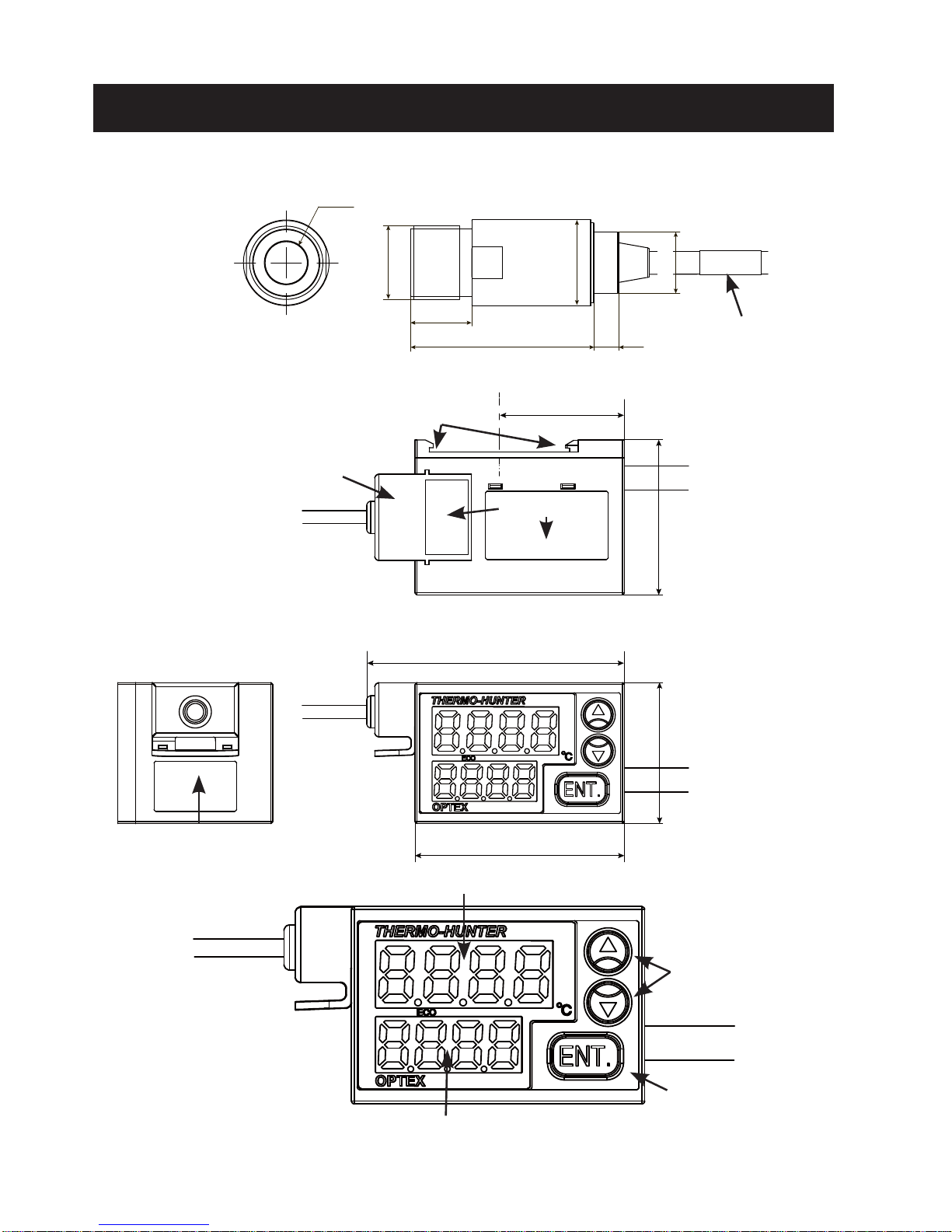
External Dimensions/Parts Name
Lens surface
φ
7
M12 × P1.0
10
30
φ14
Sensor head
Sensor cable
φ
4×3000 (MAX)
Cable cover
Serial No.
▲/▼
buttons
ENT. button
Output cable
φ
6×2000 (MAX)
Cable No.
Main display
Amplifi er
Sub display
64
52
35
38.5
31
[mm]
DIN rail attachment part
Cable No.
φ10
4
Page 6
6
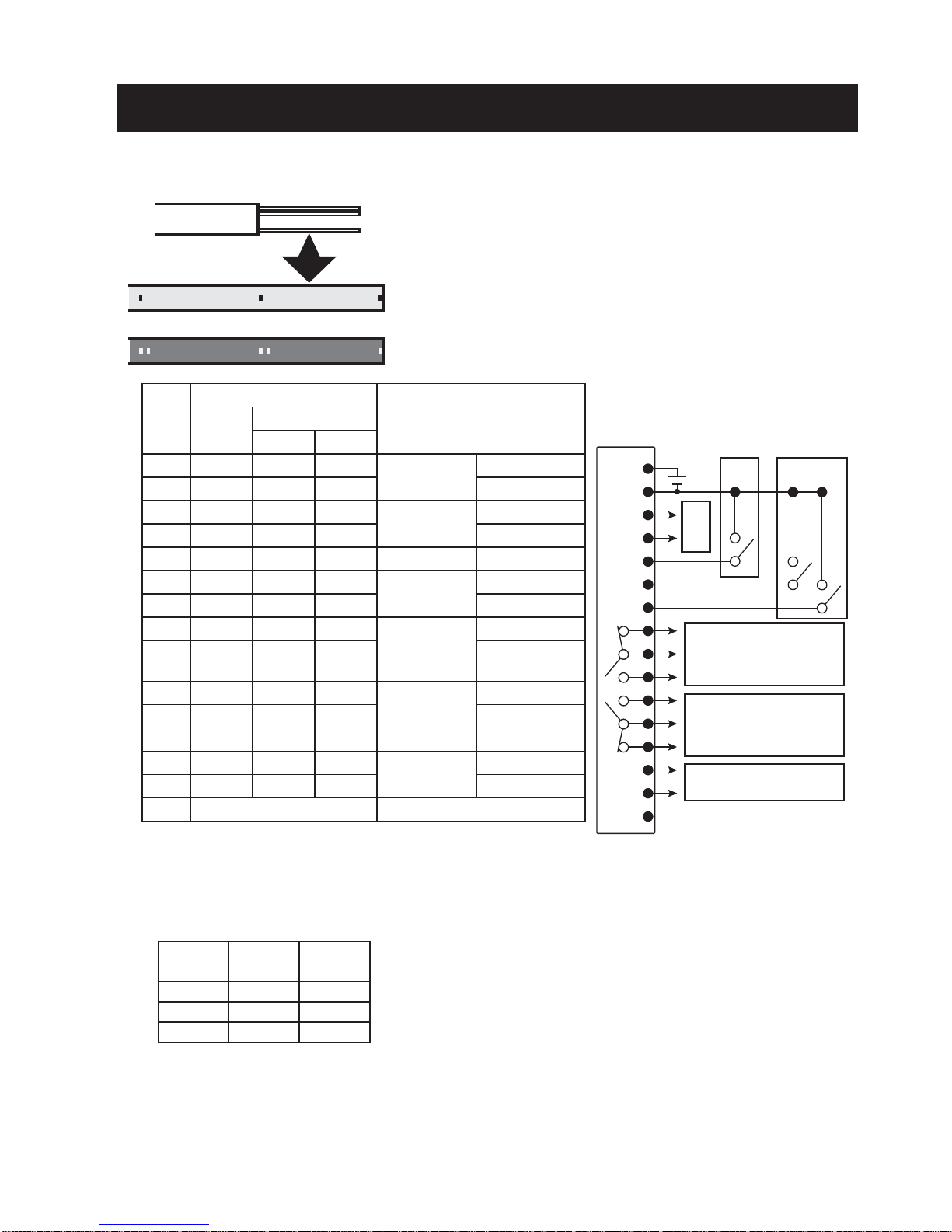
Wiring Diagram
BANK (1) (2)
1 OPEN OPEN
2 CLOSE OPEN
3 OPEN CLOSE
4 CLOSE CLOSE
.
.
.
15 pieces
Dot mark 1
Dot mark 2
No.
Output cable
Descriptions
Line
color
Dot mark
Color
Quantity
1 Pink Red 1
Power supply
12 to 24 VDC
2 Gray Black 1 GND
3 White Red 1
Analog output
4-20 mA
+
4 White Black 1
-
5 Pink Black 1
External trigger
Input
6 Gray Black 2
Bank switch
(1)
7 White Red 2 (2)
8 Yellow Red 1
Alarm output
H
N.C.
9 Gray Red 1 COM
10 Yellow Black 1 N.O.
11 Orange Red 1
Alarm output
L
N.O.
12 Gray Red 2 COM
13 Orange Black 1 N.C.
14 Orange Red 2
Digital output
Output
15 Orange Black 2 Input
16 *4 (Shielded cable)
-
Output cable
*1 Connect to the 4-20 mA input of an analog device.
Analog output allowable load 250Ω and analog output impedance 47 Ω
*2 External trigger: Switches on/off in the range from 2 to 5.
*3 Bank switch: Switches OPEN/CLOSE in the range from 2 to 6 or from 2 to 7 to select a bank.
*2 *3
c contact
300 mA/30 VDC or less
c contact
300 mA/30 VDC or less
Communication option -> PC
*1
*4 When you cut the output cables shorter, a shielded cable for reinforcement will come out. Cut the
shielded cable to prevent it from contacting with other cables.
* Cables not used should be cut so that they do not contact with other cables, and insulated with
adhesive tape or by other methods.
Page 7
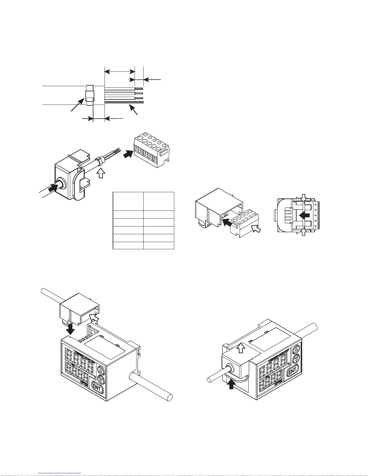
7
Sensor
cable
Connector
No.
Green 1
Yellow 2
Brown 3
Shield 4
-
5
When you cut the sensor cables, ensure to perform
end treatment and connection of the cables.
(1) Cut the cables to a desired length and treat their
end as shown in the left fi gure.
A guide wire is sheathed in the shielded mesh
cable. Cut the other cables than the guide wire at
their base.
(2) Pass the sensor cable bundle through the hole
of the cable cover and tighten the cable tie at the
point shown in the left fi gure.
* The serial numbers are printed on the cable cover.
Make sure to put each sensor cables back to the
same holes that you removed.
(3) Connect the cables and shielded cable (guide
wire) to the connector.
(4) Insert the connector to the cable cover.
*The metal plate of connector should be placed onto
the clasp in the cable cover.
Sensor cable
5
15
5
Cable tie
(of approx. 2
mm width)
Guide wire
(1)
(2)
(3)
(4)
[mm]
○
Connecting the sensor cables
Keeping the connector pushed
in, fi t the cable cover to the
grooves of the amplifi er, and
insert the cable cover.
○
Removing the sensor cables
Pinch the tab of the cable
cover and pull the cable cover
upward.
Sensor head and amplifi er has
been adjusted in one set. When
you connect both, make sure
that the serial number of cable
matches the serial number of
amplifi er.
Amplifi er is not a protective structure. When you connect the output cable and the sensor cable,
make sure that the water or oil does not penetrate to amplifi er along the cable. When used in such
an environment where water or oil might get in to the amplifi er, please use optional protective case.
(Equivalent to IP65)
Please noted that continuous hot water with high pressure may cause breakage of the cable or covering.
Page 8

8
Mounting/Installation
Sensor head
Amplifi er
Mount the amplifi er on the DIN rail using the hooks on its bottom.
Avoid a location where water or oil may spill on it.
○
Mounting
Make the two hooks on the SW side catch the
DIN rail and push in to set the amplifi er.
(1)
(2)
(1)
(2)
○
Removing
Push the two hooks on the SW side to the
opposite direction and raise the amplifi er.
The external screw is M12 × P1.0.
Fix securely into the hole of φ12 mm or more using the attached hexagon nut.
The optional mounting fi tting can help you adjust the angle easily.
○
Mounting
Mount the sensor head perpendicular to the
target.
Avoid a location where the sensor head may
be exposed to vibration or impact.
The ambient temperature should not rapidly
change and should be within the operating
temperature range.
Do not fi x the cable when it is bent or
excessive load is applied to it.
Although the sensor head is water-resistant,
water drops on the lens may cause an error.
90°
Target
Page 9

9
Field of View
[CS-30TAC/CS-30TAC-HT]
[CS-40TAC/CS-40TAC-HT]
φ 12/100
φ 21/300
φ 30/500
φ 14/100
φ 27/300
φ 40/500
[CS-30TAC/CS-30TAC-HT + CF]
[CS-40TAC/CS-40TAC-HT + CF]
φ 0.6/12 φ 1.0/12
φ 25/50φ 26.5/50
[For correct measurement]
The range of fi eld of view is equivalent to 90% of optical response (energy).
The target measured should be suffi ciently larger than the fi eld of view shown above.
When measuring a high-temperature target, keep as much distance from it as possible within the range
of the fi eld of view.
If the main body rapidly heats up, a measurement error may occur.
When using the optional CF lens
* When the CF lens is attached, correction is necessary because light intensity received from the target
decreases by 20 to 30%.
When measuring a minute spot, the recommended target size is approximately 1.5 times of the fi eld
of view shown above.
[mm]
[mm]
Area size/Distance
Area size/Distance
D (distance) : S (area) = 22:1
D:S = 15:1
φ 7/0
φ 7/0
Page 10

10
How to Use
(1) Check that the connections are correct and turn the power
on.
The display fl ashes and temperature measurement starts.
(2) Check that the unit performs normal operation.
Put your hand over the head part to check that the
measurement value changes.
* A measurement error may occur just after the sensor head is
mounted.
25
E1.00
MODE
8888
BANK
1
(1) BANK
DELY
1
(2) DELY
TADJ
E1.00
(3) TADJ
ASCL
-40
(4) ASCL
ALAM
400
(5) ALAM
TRIG
NoN
(6) TRIG
ECO
OFF
(7) ECO
END
SET
(8) END
Normal measurement
ENT.
Press 3 sec. or more
MODE indication
fl ashes and the unit
enters the setting
mode.
* The indications above are factory setting.
The sub indication values of ASCL and ALAM are different
depending on the model.
8.8.8.8
8.8.8.8
(3) To check the Setting values, switch the setting modes.
(4) Press the ENTER Button for three seconds or more to switch
the setting mode.
The unit enters the setting mode when the BANK indication
appears after the MODE indication fl ashes.
(5) Select the item with ▲/▼ buttons to check the setting.
MODE
Page 11

11
Function List
To change the settings, press the ENTER button for three seconds or more.
The settable items are shown below.
Change the settings as necessary.
While the indication fl ashes, the settings are being read or written and the button operation
is not accepted.
No. Indication Name Descriptions Page
(1)
BANK
Bank Select the bank (1 to 4) to change the setting.
12
Individual setting is possible for each of 1 to 4 banks. Switching the
bank by cable connection can call up the saved setting.
(2)
DELY
Delay Select the response time.
12
The response time changes as you change the number of moving
average times. The response time is delayed more as you increase the
number, which is effective to minimize fl uctuation of measurement values.
(3)
TADJ
T-Adjust
Make the temperature measurement settings such
as emissivity rate.
12
You can change the emissivity rate and make simple temperature
adjustment.
(4)
ASCL
Analog Scale
Change the output temperature width of analog
output.
15
You can specify a desired measurement width for analog output (420mA) within the measurement temperature range.
(5)
ALAM
Alarm Make the contact output settings.
16
You can select ON/OFF, type and temperature for alarm output.
(6)
TRLG
Trigger Make the trigger input settings.
18
You can specify the type of trigger input as a switch to execute output
control.
(7)
ECO
ECO Set the ECO mode.
21
You can set the ECO mode in order to reduce current consumption by
turning off the display of main unit.
(8)
END
End Save the modifi ed settings.
21
You can save the Setting values in the bank or switch to the next bank
to change the setting.
* The values confi rmed with SET will be deleted if they are not saved
in this mode.
If the unit is left unoperated for ten seconds or more, it returns to the measurement mode. At
the time, the settings not saved by END -> SET will be deleted.
MODE
8888
END
SET
END
SET
BANK
1
Flashing / Button operation is not possible Lighting / Button operation is possible
Page 12

12
TADJ
E1.00
Setup of Functions
Make the temperature measurement settings.
TECH: Input the temperature value of the target to automatically
calculate the emissivity rate.
ε
: Input the emissivity rate directly.
AADJ: The display value can be adjusted in accordance with the
specifi ed value (within the measurement temperature range).
NON: Cancel the TADJ mode. The unit returns to the function
selection mode.
TECH
E1.00
E
E1.00
AADJ
OFF
TECH
ε
AADJ
NON
SET
NON
●
TADJ
:
TADJ/ Thermo Adjust mode
Select the bank No. to make the setting.
There are four banks (1 to 4) in total, each of which can have its own
setting.
The No. displayed fi rst is that of the bank enabled in normal
operation.
* The bank enabled in normal operation should be selected by
connecting the cable.
You cannot select it in the setting mode.
(1) Enter the BANK mode select the bank No.
(2) Press the ENTER button to confi rm the setting.
* Switch banks in END mode, when changing the setting value for
each bank in succession.
* The changed values for setting become effective by saving them in
END mode(SET).
DELY
1
BANK
1
BANK
4
DELY
200
Select the response time.
You can select the value between 1 and 200 of the number of moving
average times. Selecting a larger value will delay the response time
more.
1 = response time of the product (0.15 sec.) to 200 = approximately
10 sec.
This setting can average (smooth) fl uctuation of measurement
values and large variation of temperature.
(1) Enter the DELY mode select the value.
(2) Press the ENTER button to confi rm the setting.
●
BANK
:
BANK/ Bank mode
●
DELY
:
DELY/ Delay mode
Indications of selectable settings
* Setting NON with SET returns the unit to
the state of before making the setting.
Page 13

13
TECH
E1.00
150
150
150
160
160
E0.90
E
E1.00
E
E0.95
Emissivity rate (ε)
The emissivity rate is the rate of energy emitted from the surface of an object. Every object has
a unique emissivity rate which is variable according to the surface condition and temperature
of the object. This product allows for setting a desired emissivity rate, which can enable even
more precise measurement by adjusting the emissivity rate according to that of the target.
An object with low emissivity rate (e.g. a shiny metallic object) refl ects the surrounding
temperature since it is highly refl ective. If the surrounding objects have greatly different
temperature from that of the main unit, their temperatures are refl ected resulting in incorrect
measurement. Therefore it is necessary to block out such effect.
The maximum emissivity rate is normally 1.00, but this unit is designed to accept up to 1.20 for
practical convenience.
(1) Press the ENTER button in the Teach mode after confi rming the target
is aimed suffi ciently larger than the fi eld of view.
(2) When the current measurement value is displayed, input the
temperature of the target.
(3) Press the ENTER button to confi rm the setting.
(4) Check that the indicated value and emissivity rate have been changed.
(1) In the ε mode, press the ENTER button to make the
setting.
(2) Directly input the emissivity rate.
(3) Check that the indicated value and emissivity rate
have been changed.
○
TECH
:
TECH/ Teach mode
○E:
ε
/ Emissivity mode
Err1
E
In the TECH mode, if the automatically calculated emissivity rate is outside the
setting range (0.1 to 1.2), an error (Err1) occurs. In this case, the emissivity rate
cannot be set in the TECH mode. Set it in the ε mode again.
Err2
E
In the TECH mode, if the temperature measurement value calculated with the
automatically calculated emissivity rate is outside the measurement temperature
range, an error (Err2) occurs. In this case, the emissivity rate cannot be set in
the TECH mode. Set it in the ε mode again.
Error indication
An error is displayed when the set item or input value is incorrect.
Perform the procedures below when an error is displayed.
Page 14

14
Setup of Functions
AADJ
OFF
AADJ
ON
L
EXIt
100
120
120
SET
H
EXIt
L
SET
H
SET
250
300
300
SET
○
AADJ
:
AADJ/ Analog Adjust mode
(1) Set the AADJ mode to ON and press the ENTER button to make
the setting.
(2) Press the ENTER button after confi rming the target is aimed
suffi ciently larger than the fi eld of view.
(3) Check that the target is in the measurement area. The current
measurement value appears on the display. Press the ▲/▼
buttons to input the temperature L (lower limit value) of the target.
(4) Press the ENTER button to confi rm the setting.
(5) Check that the indicated value has been changed.
* To input the value later, select EXIT.
This setting is for adjusting the measurement value with the specifi ed value
according to the measuring targets. A intended value can be output by setting
L (lower limit value) and H (upper limit value) conforming to the both specifi ed
value.
* Measurement accuracy can not be guaranteed for the value made by AADJ
mode.
* Please do not change emissivity after setting in the AADJ mode, otherwise
the adjusted value will be changed.
(1) Set the AADJ mode to ON and press the ENTER button to make
the setting.
(2) Press the ENTER button after confi rming the target is aimed
suffi ciently larger than the fi eld of view.
(3) Check that the target is in the measurement area. The current
measurement value appears on the display. Press the ▲/▼
buttons to input the temperature H (upper limit value) of the target.
(4) Press the ENTER button to confi rm the setting.
(5) Check that the indicated value has been changed.
* To input the value later, select EXIT.
* If the timings to set L and H are different (e.g., when using the same target for setting L and
H), set either of them fi rst and save the setting with END. Otherwise the input value will be
canceled.
The adjusted value are effective after the both of L and H value are set
and stored. When AADJ mode on, AADJ is displayed as sub indication.
The measuring value is output according to the setting value previously
stored, if the setting of L and H value are stored in EXIT mode with AADJ
mode on. In this process, AADJ is also displayed as sub indication.
EXIT
300
AADJ
* Either the upper or the lower limit value can not be changed after the
setting is completed.
Page 15

15
ASCL
-40
You can change the temperature range of analog
output (4 - 20 mA) within the measurement
temperature range.
H (upper limit value): Value for 20 mA output
L (lower limit value): Value for 4 mA output
* The value of sub indication displayed fi rst is the
current Setting value.
●
ASCL
:
ASCL/ Analog Scale mode
ASCL
500
(1) In the ASCL mode, press the ENTER button to
make the setting.
(2) H (upper limit value) is displayed.
Change the value and press the ENTER button to
confi rm the setting.
H
500
H
300
L
-40
L
0
(3) L (lower limit value) is displayed.
Change the value and press the ENTER button to
confi rm the setting.
* The minimum width of output range is 100°C. You cannot set it to less
than 100 °C.
0 to 1000 °C: 4 – 20 mA -> 100 to 200 °C: 4 – 20 mA ○
-> 100 to 180 °C: 4 – 20 mA ×
250
100
300
250
100
120
Temperature
Energy Energy
Temperature After adjustment
‑40℃
500℃
4mA 20mA
0℃
300℃
4mA 20mA
Temperature
Output Output
Temperature
* The minimum temperature width for upper limit value and lower limit
value is 10 degree.
Page 16

16
Setup of Functions
●
ALAM
:
ALAM/ Alarm (contact) output mode
ALAM
400
You can set the temperature and output method of
alarm (contact)output.
H (upper limit value): Output turns on when the value
exceeds the Setting value.
L (lower limit value): Output turns on when the value
falls below the Setting value.
Select one of the three types of OUT (output) mode:
NOR, DEL and ONES.
ALAM
50
OUT
NOR
OUT
DEL
OUT
ONES
NOR
DEL
ONES
L
ON
OFF
H
L
ON
OFF
H
t
L
ON
OFF
H
t
t: Time to delay output
t: Time to keep output on
ONES: Output turns on when the value exceeds or falls
below the set temperature and is kept for a specifi c time.
NOR: Output is kept on as long as the value is over or below
the set temperature.
DEL: Output turns on when a specifi c time period passes
after the value exceeds or falls below the set temperature.
Measurement value
Measurement value
Measurement value
Contact output
Contact output
Contact output
Page 17

17
○
OUT
:
OUT/ Output mode
H
OFF
H
ON
H
400
H
300
L
OFF
L
ON
L
50
L
0
OUT
NOR
OUT
DEL
TIME
0.010
TIME
2.000
OUT
ONES
TIME
0.010
TIME
2.000
(1) Switch from OFF to ON and press the ENTER button to confi rm the
setting.
(2) When the upper limit value is displayed, press the ▲/▼ buttons to input
the temperature.
(3) Press the ENTER button to confi rm the setting.
* To cancel the setting, select OFF and press the ENTER button.
(1) Switch from OFF to ON and press the ENTER button to confi rm the
setting.
(2) When the lower limit value is displayed, press the ▲/▼ buttons to input
the temperature.
(3) Press the ENTER button to confi rm the setting.
* To cancel the setting, select OFF and press the ENTER button.
Select the output mode.
To set to the NOR mode, press the ENTER button to confi rm the setting.
To set to the DEL mode,
(1) Switch to the DEL mode and press the ENTER button to confi rm the
setting.
(2) When the time to delay output (TIME) is displayed, press the ▲/▼ buttons
to input the time. The settable range is between 0.01 to 2.00 seconds.
(3) Press the ENTER button to confi rm the setting.
To set to the ONES mode,
(1) Switch to the ONES mode and press the ENTER button to confi rm the
setting.
(2) When the time to keep output (TIME) is displayed, press the ▲/▼ buttons
to input the time. The settable range is between 0.01 to 2.00 seconds.
(3) Press the ENTER button to confi rm the setting.
TIME
Page 18

18
TRIG
NoN
You can select the output control at the time of trigger (synchronous) input.
NONE: No setting
EXT: External trigger input
WAVE: WAVE trigger input
* Output is controlled by setting the specifi ed temperature as the judgment
criterion value (WAVE LIMIT).
Output setting
MAX: The maximum value between the synchronous input points is output.
MIN: The minimum value between the synchronous input points is output.
P-P: The difference between the maximum and minimum values between
the synchronous input points is output. (For EXT only)
SAMP: The value at the moment of synchronous input is output. (For EXT only)
TRIG
NoN
TRIG
EXT
TRIG
WAVE
NON EXT WAVE
●
TRIG
:
TRIG/ Trigger (synchronous) input mode
HOLD
MAX
HOLD
MIN
HOLD
P-P
MAX HOLD
MIN P-P
HOLD
SAMP
SAMP
Setup of Functions
MIN
ON
OFF
MAX
MIN
MAX
ON
OFF
MIN
MAX
ON
OFF
MIN
MAX
ON
OFF
MIN HOLD
MAX
P-P HOLD
SAMPLE HOLD
Trigger input Trigger input
Trigger inputTrigger input
Analog output
Analog output
Analog output
Analog output
Measurement
value
Measurement
value
Measurement
value
Measurement
value
Page 19

19
TRIG
EXT
(1) In the TRIG mode, select EXT and press the ENTER button to confi rm the
setting.
(2) Select the analog output at the time of trigger input.
(3) Press the ENTER button to confi rm the setting.
○
EXT
:
EXT/ External Trigger mode
HOLD
MAX
HOLD
MIN
HOLD
P-P
HOLD
SAMP
TRIG
WAVE
(1) In the TRIG mode, select WAVE and press the ENTER button to confi rm
the setting.
(2) Select the analog output at the time of WAVE trigger input.
(3) Input the WLIT/WAVE LIMIT value.
(4) Press the ENTER button to confi rm the setting.
* In the WAVE mode, the selectable output setting is MAX or MIN only.
○
WAVE
:
WAVE/ Wave Trigger mode
HOLD
MAX
HOLD
MIN
WIMT
200
WLIM
150
WIMT
200
WLIM
150
* After the power is turned on and before the fi rst trigger is input, the minimum value (4 mA) is output in
the MAX, P-P and SAMPLE settings and the maximum value (20 mA) in the MIN setting.
Sampling starts at the fi rst trigger input, and the analog output control starts from the second trigger
input.
MIN
ON
OFF
MAX
WAVE
LIMIT
WAVE MAX HOLD
MIN
ON
OFF
MAX
WAVE
LIMIT
WAVE MIN HOLD
* If the alarm output has been set, the judgment criterion will be the analog output controlled by the
trigger input setting. -> Page 20
Trigger input Trigger input
Analog output
Analog output
Measurement value
Measurement value
Page 20

20
●
Combination of alarm output and trigger input
Setup of Functions
This unit allows individual setting for each function.
The behavior when the alarm output and trigger input are combined is as described below.
The alarm output uses the analog output value as the judgment criterion, so when the trigger
input is set, the controlled analog output will be the judgment criterion.
MIN
ON
OFF
MAX
MAX HOLD
H
L
H ON
OFF
L ON
Setting value
Alarm: H/L setting NOR output
Trigger: External trigger MAX HOLD
According to the analog output of MAX
HOLD set by the trigger input, alarm
is output while the value is outside the
range between H and L.
Setting value
Alarm: (1) H/L setting NOR output
(2) H/L setting DEL output
(3) H/L setting ONES output
Trigger: WAVE trigger MAX HOLD
According to the analog output of MAX
HOLD set by the trigger input, alarm
is output while the value is outside the
range between H and L.
t
t
MIN
ON
OFF
MAX
WAVE
LIMIT
H ON
OFF
L ON
H
L
H ON
OFF
L ON
H ON
OFF
L ON
t
t
ECO
OFF
You can reduce consumption current by turning off the display during normal
measurement.
(1) Enter the ECO mode and select ON.
(2) Press the ENTER button to confi rm the setting.
(3) Input the time that elapses before the display is turned off.
The settable range is between 1 to 600 seconds.
(4) Press the ENTER button to confi rm the setting.
ECO
ON
●
ECO
:
ECO mode
ECOT
1
ECOT
600
.
When ECO is ON
A single dot is lighting.
Trigger input Trigger input
Contact output
Contact output
(1) NOR
Contact output
(2) DEL
Contact output
(3) ONES
Analog output
Analog output
Measurement value
Measurement
value
Page 21

21
END
SET
You can save (SET) or cancel (CSEL) the setting and change the bank No. to
make the setting.
* The Setting values become valid only after they are saved. The setting is
restored to its previous state if the unit returns to the measurement mode
without saving them or the Setting values are canceled.
(1) Enter the END mode and select SET
(save) or CSEL (cancel).
(2) Press the ENTER button to confi rm the setting.
(3) The unit returns to the normal measurement mode.
To switch the bank to make the setting
(1) Enter the END mode and select the number from 1 to 4.
(2) The unit enters the setting mode for the selected bank. Make the
necessary setting.
END
CSEL
●
END
:
END mode
BANK
DELY
ε
AADJ L
=℃
→
℃
H
=℃
→
℃
ASCL L(4mA)
=℃
H(20mA)
=
℃
ALAM
L
=℃H=℃
NOR DEL ONES
TIME ms
TRIG
EXR
MAX MIN P-P SAMP
WAVE
MAX MIN
WLIT
:
WAVE LIMIT
℃
ECO
ON OFF
TIME ms
[Note of the setting]
END
1
SET
CSEL
END
4
Page 22

22
Problem Cause Action
Cannot measure.
The power is not applied. Check the cabling and connections.
The power voltage is low.
Check the power voltage and adjust it to
the 12 to 24 VDC range.
The
measurement
value is wrong.
The lens is dirty.
Clean the lens referring to the Lens section
under “Maintenance”.
The measurement area is off center.
Adjust the mounting position so that the
target comes to the center of the area.
A high-temperature object is near the
target affecting the measurement.
Block the heat source using a board, etc.
The emissivity rate setting is not
correct.
Set the emissivity rate to that of the target.
The measurement
value is not
stable.
The sensor head is affected by
vibration.
Prevent vibration.
The sensor head is affected by rapid
temperature change.
Leave the sensor head for a while until the
temperature becomes stable.
Troubleshooting
Maintenance
Lens Dust, dirt and scratches on the lens can cause incorrect measurement. If the lens is dirty,
remove the dust using a blower for cleaning lens. For stubborn dirt, apply a small amount
of ethyl alcohol to a cotton swab or special lens cleaning cloth and gently wipe off the dirt.
Amplifi er For heavy dirt on the amplifi er, use a lightly moistened cloth to wipe it off. Do not use
alcohol or such other material because it may damage the surface or fade the printing.
Calibration Yearly calibration is recommended. The sensor head and amplifi er cannot be separately
calibrated. Always calibrate them together. For details, contact the sales distributor.
* If the problem persists even after taking the actions above or the problem is not listed here, contact
the sales distributor
.
You can rinse the sensor head with water because it is water-resistant. However, water drops remaining
on the lens will cause incorrect measurement. Be sure to wipe them off with a soft cloth or blow them off
with air.
You can easily remove water or oil by using air as the water/oil-repellent coat is applied on the surface
of lens.
If the unit may be exposed to splash of water or oil or located in a dusty place during measurement, use
the optional air purge collar.
 Loading...