

Page 1
PHOTOELECTRIC DETECTOR
AX-250PLUS, AX-500PLUS
< STANDARD >
Take care of the environment.
This manual uses recycledpaper.
No. 59-1365-0 0608-07
INSTALLATION MANUAL
AX-350TF, AX-650TF
< 4 SELECTABLE BEAM FREQUENCIES >
Please read intsructions completely before beginning installation.
Photoelectric detectors detect intruders when both the upper and lower invisible infrared beams are simultaneously broken.
Maximum detection range between Transmitter and Receiver for the AX-250PLUS is 250ft. (75m), the AX-500PLUS is 500ft. (150m) and for the
AX-350TF is 350ft. (100m), the AX-650TF is 650ft. (200m)
• Beam interruption time adjustment
• Anti-Frost Structure
• Alignment level monitor jack
• Form C relay
• Tamper
• Option
• UL Listed
AX-350TF, AX-650TF ONLY
• LED indicator for fine beam alignment level
• Selectable beam frequencies
• Re-Transmit Circuit
• D.Q.Circuit (Environmental Disqualification)
• Alarm Memory
FEATURES
: This function allows you to select the suitable beam interruption time for any environment.
: Prevents fog and condensation from blocking the beams.
: Can easily obtain maximum optical alignment by checking the voltage from this jack.
: Form C relay for more applications.
: N.C., Opens when cover is removed.
: Heating unit (HU-1), Back cover (BC-1) AX-Beam Tower (AX-BT)
: The optical alignment level can be checked at the Reciver.
: Crosstalk is eliminated with 4, channel selectable, beam frequencies. Used when stacking beams
or for long range applications.
: The advantage of this method is the elimination of wiring, from a detector or switch, back to the
control panel.
: The environmental compensation circuit is designed to eliminate false alarms caused by snow,
fog, heavy rain, ice and misalignment.
For Safe Use of the Product
• Read this instruction manual carefully prior to installation.
• After reading, store this manual carefully in an easily accessible place for reference.
• This manual uses the following warning indications for correct use of the product and harm to you or other people and damage to your assets, which
are described below. Be sure to understand the description before reading the rest of this manual.
WARNING
CAUTION
This symbol indicates prohibition. The specific prohibited action is provided in and/or around the figuer.
This symbol requires an action or gives an instruction.
WARNING
CAUTION
Failure to follow the instructions provided with this indication and improper handling may cause death or serious injury.
Failure to follow the instructions provided with this indication and improper handling may cause injury
and / or property damage.
Do not use the product for purposes other than the detection of moving objects such as people and vehicles.
Do not use the product to activate a shutter, etc., which may cause an accident.
Do not touch the unit base or power terminals of the product with a wet hand (do not touch when the
product is wet with rain, etc.). It may cause electric shock.
Never attempt to disassemble or repair the product. It may cause fire or damage to the devices.
Do not exceed the voltage or current rating specified for any of the terminals during installation, doing so
may cause fire or damage to the devices.
Do not pour water over the product with a bucket, hose, etc. The water may enter, which may cause damage
to the devices.
Clean and check the product periodically for safe use. If any problem is found, do not attempt to use the
product as it is and have the product repaired by a professional engineer or electrician.
C O N T E N T S
1.PARTS IDENTIFICATION ····································· P2
2.PRECAUTIONS ····················································· P2
3.INSTALLATION METHOD ···································· P3
4.AX-250/500PLUS
4-1.TERMINAL ······················································ P4
4-2.WIRING ··························································· P4
4-3.OPTICAL ALIGNMENT ·································· P5
5.AX-350/650TF
5-1.TERMINAL ······················································ P6
5-2.WIRING ··························································· P6
5-3.OPTICAL ALIGNMENT ·································· P7
6.BEAM INTERRUPTION
TIME ADJUSTMENT ············································ P8
7.AX-350/650TF
7-1.SELECTABLE BEAM FREQUENCIES ·········· P8
7-2.ALARM MEMORY ·········································· P8
7-3.DQ CIRCUIT ··················································· P9
7-4.RE-TRANSMITTING CIRCUIT ······················· P9
8.SPECIFICATIONS ··············································· P10
9.DIMENSIONS ······················································ P10
10.TROUBLE SHOOTING
CHECK SHEET ············································ P11,P12
1
Page 2
2
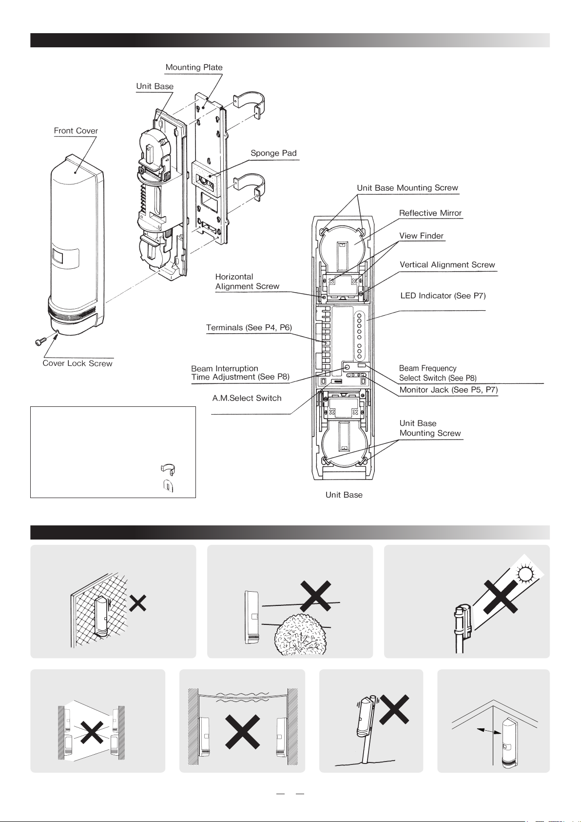
1. PARTS IDENTIFICATION
(AX-350/650TF only)
(AX-350/650TF Receiver only)
(AX-350/650TF only)
2. PRECAUTIONS
2. Do not install the unit where objects
moved by the wind such as plants and
laundry, which may block the beam.
1. Mount unit only on a solid surface.
3. Prevent direct sunlight
from entering into internal
receiver.
5. Avoid aerial wiring.
4. A different type of beam
should not reach the receiver.
receiver
transmitter
(other model)
transmitter
6. Do not install the unit
on unsteady surfaces.
7. Mount the units more
than 1m away from the
wall or fence.
STANDARD ACCESSORIES
○
Screws (4×20 Self tapping)×8
○
Screws (M4×30)×8
○
U-Shaped brackets ×4
○
Beam Blocking Tool
×2
3.3 ft. (1m)
Page 3
3. INSTALLATION METHOD
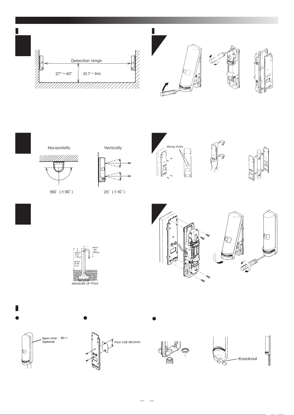
a. General
Detection range and installation height.
1
Maximum distances between Receiver and Transmitter are listed below.
AX-250PLUS = 250ft (75m) Max
AX-500PLUS = 500ft (150m) Max
AX-350TF = 350ft (100m) Max
AX-650TF = 650ft (200m) Max
and the installation height should be at 27"~40". (0.7~1m)
Alignment angle
2
b. Installation Method
1
Lossen the cover lock screw and remove the front cover. And loosen the
unit base mounting screw and remove mounting plate by sliding it down
against the unit base.
well mounting
2
Pole mounting
Two unit installation
(back to back)
Pole mounting
3
* Pole size should be as follews: 1 3/8"~1 7/8" O.D (Ф34~Ф48mm)
(Standard U.S. 1 1/4" or 1 1/2" pipe.)
* The length of the wiring cable out of the pole should be within 20
inches (60cm).
* Face transmitter and receiver towards each other when pole mounting.
NOTE
Pull out the wire through the
wirin g ho le on t he m ounting
plate and attac h the plate to
the well with the screw.
3
* C on ne ct wi re to t he te rm in al s
(See Sec. 4-1, 5-1 "Terminal").
Pla ce U- Sh ap e br ac ke ts
at the top of the p ole . An d
pull out the wire t hrough the
wirin g ho le og t he M ounting
pl ate , a ttac h th e mo ut ing
plate to the U-Shape bracket
with screw.
* A fter c hecking opt ica l a lig nmen t
and operation check (See Sec. 4
-3 , 5 -3 O PTICAL ALI GN MEN T),
re pl ac e th e co ve r, an d fa st en
the lock screw tightly.
Fix two U-shape brackets in
la yer s o n a pol e, two uni ts
can be installed back to back
on a pole at the same height.
Pole Mount Back Cover Electric Box Mounting
For connections to single gang
electric boxes, follow intructions for
wall mounting.
Conduit Installtion
Conduit can be installed directly into the bottom of the unit by removihg the
knockout on the bottom of the cover.
3
Page 4
4. AX-250/500PLUS
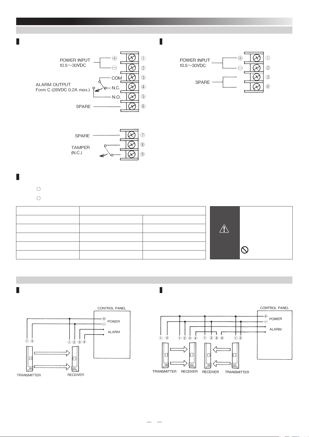
4-1. TERMINAL
Receiver Transmitter
Wiring Distance
Wh en using two or more units on one wire , the max imum le ngth is obt ained by divid ing the wire len gth lis ted bel ow by the
number of units used.
Power wires should not exceed the following length.
MODEL AX-250/500PLUS
WIRE SIZE 12V DC 24V DC
AWG22 (0.33mm
AWG20 (0.52mm
AWG18 (0.83mm
AWG16 (1.31mm
UL requires AX-250PLUS/500PLUS to be connected to a UL listed power supply capable of providing a
norminal input of 12VDC, (10.5~30VDC) 50mA and battery standby time of 4 hours.
2
) 1300' (400m) 7500' (2300m)
2
) 2000' (600m) 12000' (3600m)
2
) 3300' (1000m) 19000' (5800m)
2
) 5000' (1500m) 30000' (9200m)
4-2. WIRING
1 Set 2 Set in the line
WARNING
Do not exceed the voltage
or current rating specified
for any of the terminals
during installation,
doing so might cause fire
or damage to the devices.
4
Page 5
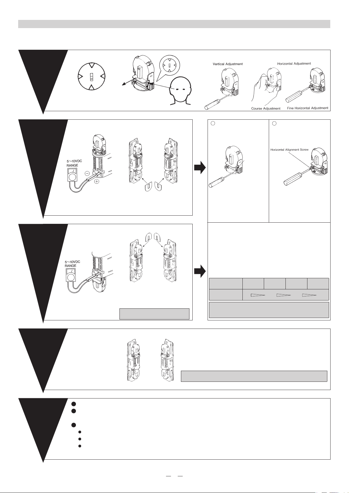
4-3. OPTICAL ALIGNMENT
When using two or more units on wire, the maximum length is obtained by dividing the maximum wire length listed below of units used.
Power wires should not exceed the following lengths.
STEP1
Looking through the view finder,
locate the other detector in the
center of the sights by adjusting
vertically and horizontally.
STEP2
Connect the volt-meter to
monitor jack input on Receiver's
(+) and (-), then fine tune optical
alignment.
Rough alignment by
view finder
Upper Mirror Fine
Adjustment
Adjust the optical alignment for
Transmitter and Receiver one at a
time.
Put the attached "Beam Blocking
Tool" on the lower mirror of both the
transmitter and the Receiver.
Looking through the view finder, locate the other detector in the
center of the sights by adjusting vertically and horizontally.
1
Vertical Adjustment
Vertical Alignment
Adjust the vertical alignment
screw to obtain the maximum
voltage from the monitor jack.
2
Horizontal Adjustment
Screw
Adjust the vertical alignment
screw to obtain the maximum
voltage from the monitor jack.
STEP3
Check the voltage using the
monitor jack and make any fine
adjustments the lower mirror.
STEP4
Lower Mirror Fine
Adjustment
Final checking after
removing the “Beam
Blocking Tool” from
the mirror.
Secondly, adjust the lower morrors.
After the final adjustment are made on the upper
mirrors carefully without moving morror remove
"Beam Blocking Tool" from the lower mirrors
and place them on the upper mirrors of both the
Transmitter and Receiver.
Be carefull when removing the "Beam Blocking
Tool" from the mirror-Don't move mirrors.
Carefully remove the "Beam Blocking Tool" from the upper mirror of both
Transmitter and Receiver also check the voltage from the monitor jack again.
Then check again that the voltage from monitor jack is more than about 5.0V.
if not, adjust the optical alignment again.
After the vertical and horizontal adjustment are made, recheck
the voltage from monitor jack is over 5.0V. If not, adjust the
optical alignment again.
SENSITIVITY CHART
ALIGNMENT
LEVEL
MONITOR
JACK OUTPUT
optical Alignment for Indoor Use
obtain maximum voltage from the monitor jack, at least more
than 2.2V
Realign Fair GOOD
0V 2.0V 3.5V 5.0V
EXCELLENT
Confirmation
of
Action
1
Check that the operation indicator (“ALARM CONDITION” LED) light is OFF.
2
If the indicator light is ON even though the beams are not blocked, re-adjust the optical alignment and check
wiring. (See sec. 4-3)
3
After alignment is achiened and the units work properly, conduct a walk test at a minimum of three points.
In front of the Transmitter.
In front of the Receiver.
At the middle point between Transmitter and Receiver.
5
Page 6
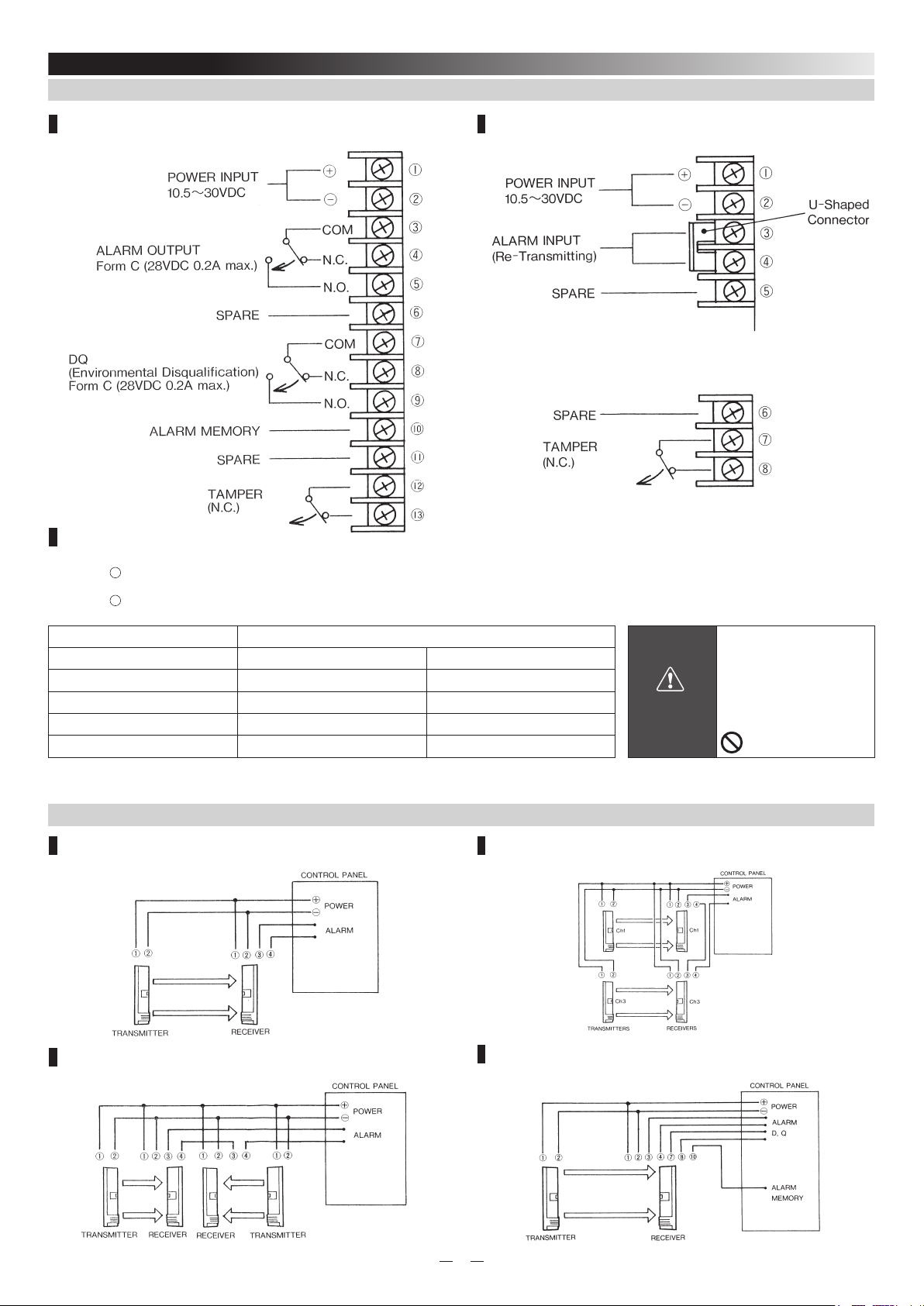
5. AX-350/650TF
5-1. TERMINAL
Receiver Transmitter
CAUTION : Make sure to connect the jumper (U-shaped connector), when not
using the retransimitting circuit. If the jumper is not connected, the
Transmitter will not transmit beam (Alarm condition).
Wiring Distance
When using two or mo re unit s on one wire, the max imum le ngth is obtain ed by div iding the wire length listed below by the
number of units used.
Power wires should not exceed the following length.
MODEL AX-350/650TF
WIRE SIZE 12V DC 24V DC
AWG22 (0.33mm
AWG20 (0.52mm
AWG18 (0.83mm
AWG16 (1.31mm
UL requires AX-350TF/AX-650TF to be connected to a UL listed power supply capable of providing a
norminal input of 12VDC, (10.5~30VDC) 75mA and battery standby time of 4 hours.
2
) 980' (300m) 4700' (1400m)
2
) 1500' (470m) 7400' (2250m)
2
) 2450' (750m) 11800' (3600m)
2
) 3900' (1150m) 18700' (5700m)
WARNING
Do not exceed the voltage
or current rating specified
for any of the terminals
during installation,
doing so might cause fire
or damage to the devices.
5-2. WIRING
1 Set
2 Set in the line
2 Sets Stacking
DQ and ALARM MEMORY
6
Page 7
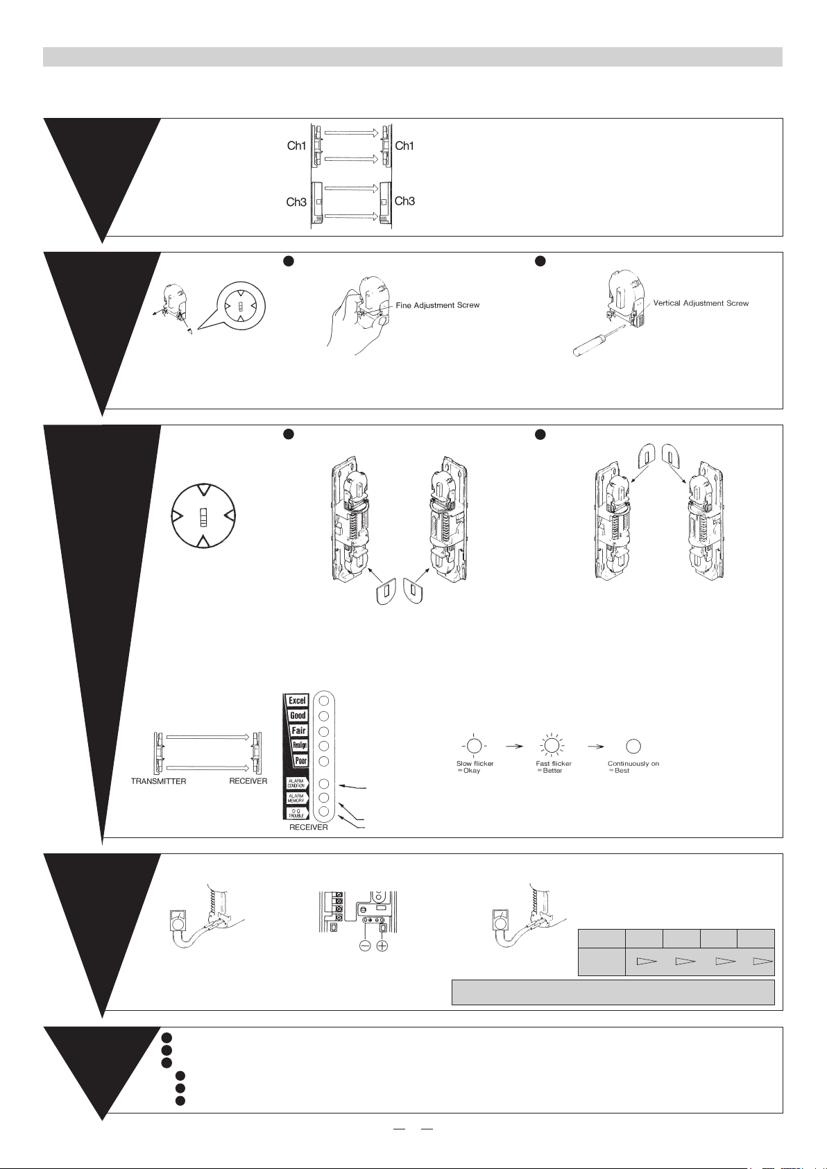
5-3. OPTICAL ALIGNMENT
When using two or more units on wire, the maximum length is obtainted by dividing the maximum wire length listed below of units used.
Power wires should not exceed the following lengths.
STEP1
Select the beam frequencies
switch.
STEP2
Looking into view finder of the
Transmitter, and adjustment the
lens holizontally and vertically,
so that the Receiver can be
seen in the center of the sight.
STEP3
Beam Frequencies
Selection
Horizontal & Vertical
Adjustment
○ Match the frequency settings. (See Sec. 7-1 SELECTABLE BEAM
FREQUENCIES.)
○ When stacking beams or installing more than one set in the same area.
1
HORIZONTAL ADJUSTMENT
Turn mirror base by hand to obtain the highest
alignment level.
Make fine adjustment by turning "Fine Adjustment
Screw".
1
ADJUST THE UPPER MIRROR
2
VERTICAL ADJUSTMENT
Turn vertical adjustment asrew to get highest level
2
ADJUST THE LOWER MIRROR
Looking into the view finder
of Receiver and make fine
adjustments horizontaly and
vertically.
STEP4
After adjusting with the LED
indicators, check the voltage at
the monitor jack output using
your meter. This will insure
proper beam alignment.
LED INDICATION
Checking From The
Monitor Jack
After the final adjustments are made on the upper
mirrors, carefully (do not move mirror) remove the
Attach the "Beam Blocking Tool" to the lower mirror
on both the transmitter and receiver.
Adjust the upper mirror.
"Excel" reading on the LED indicator is sufficient.
The alignment level indicators have 5 LEDs, each LED represents the level of alignment, ranging from poor to
excellent (See illus.)
Each LED will indicate 3 steps of alignemt, slow flicker = okay, fast ficker = better, continuously on = best
Providing 15 graduated stages.
ALARM CONDITION LED
ON: ALARM CONDITION
OFF: RECEIVING BEAM OR POWER IS NOT SUPPLIED.
ALARM MEMORY
DQ
Confirm the beam alignment level by setting your volt-meter to the 5~10V DC range, cover either the upper
or lower beam and compare the voltage reading with the following chart.
5~10V DC
RANGE
Connect the volt-meter probes
(+) to monitor jack (+), and voltmeter probes (-) to monitor jack
(-).
Set the volt-meter range
to 5~10 VDC.
Optical Alignment for Indoor Use
Obtain maximum voltage from the monitor jack, at least more than 3.4V
shieldinh tools from the lower mirrors and place them on
the upper mirrors of both the transmitter and receiver.
Make the horizontal and vertical adjustments to the
lower mirrors.
"Excel" reading on the indicator is sufficient.
Check the alignment levels of the upper and lower
beams separate from one another and ensure that
both reach excellent as stated in the chart.
ALIGNMENT
LEVEL
MONITOR
JACK
OUTPUT
SENSITIVITY CHART
Realign Fair GOOD
0V 2.0V 3.5V 5.5V
EXCELLENT
Confirmation
of
Action
1
Check that the operation indicator (“ALARM CONDITION” LED) light is OFF.
2
If the indicator light is ON even thought the beams are not blocked re-adjust the optical alignment and check wiring. (See sec. 5-3)
3
After alignment is achiened and the units work properly, conduct a walk test at a minimum of three points.
In front of the Transmitter.
In front of the Receiver.
At the middle point between Transmitter and Receiver.
7
Page 8
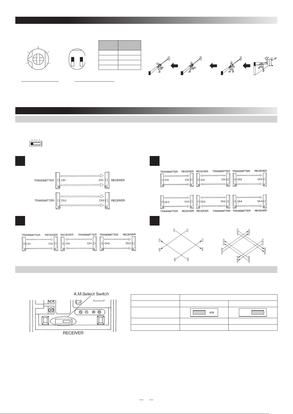
6. BEAM INTERRUPTION TIME ADJUSTMENT
200
350
100
50
(m/sec)
500
The beam interruption time adjustment is on Receiver unit. This function allows you to match the units sensitivity ti its surroundings. Slower steeings
reduce sensiticity.
ON
Interruption
time
50ms 1:OFF, 2:OFF
100ms 1:OFF, 2:ON
Switches
Running
(2.4m/s)
Jogging
(1.2m/s)
Walking
(0.5m/s)
Slow movement
(0.3m/s)
250ms 1:ON, 2:OFF
1 2
500ms 1:ON, 2:ON
[AX-250/500PLUS] [AX-350/650TF]
Selection Dip SwitchAdjustment Volume
50msec 100msec 250msec 500msec
CAUTION :
• Speeds shown above are the maximum detectable speeds for each setting. Faster speeds will not be detected. Where birds, newspapers or flying
debris can occasionally interrupt the beam, adjust setting to a slower speed (longer interruption period.)
• Beam interruption times exceeding 70 msec do not comply with the requirements in UL639. Intrusion Detection Units.
7. AX-350/650TF
7-1. SELECTABLE BEAM FREQUENCIES
BEAM FREQUENCY
SELECT SWITCH
1 2 3 4
The selectable beam frequencies can be used to avoid unwanted crosstalk that can occur when using multiple photobeams for
long distance or beam stacking applications.
• To select between 4 separate beam frequencies, use the switch provided.
• Make sure the receiver and transmitter that are facing each other are set to the same code.
IMPORTANT Always switch the frequencies TWO channels apart when stacking units on top of one another (See following example).
2 beam stacking
1
Long distance
2
7-2. ALARM MEMORY
The upper unit is set on channel 1 while the lower is on channel 3, channel 2 and 4 could have also been used.
2 beam long distance stacking
3
Perimeter protection
4
receiver(Ch1)
receiver(Ch3)
transmitter(Ch1)
transmitter(Ch3)
transmitter(Ch3)
receiver(Ch3)
receiver(Ch1)
transmitter(Ch1)
transmitter(Ch2)
transmitter(Ch4)
receiver(Ch1)
receiver(Ch3)
transmitter(Ch1)
transmitter(Ch3)
receiver(Ch2)
receiver(Ch4)
receiver(Ch2)
receiver(Ch4)
transmitter(Ch1)
transmitter(Ch3)
transmitter(Ch2)
transmitter(Ch4)
receiver(Ch1)
receiver(Ch3)
1. Wiring
Connect control voltage signal terminal (System arming status voltage output terminal) of control panel to A.M.terminal.
Model AX-350TF, AX-650TF
Type NEGATIVE
A.M.Select Switch
Position
System armed 0~1VDC(grounded) OPEN or + 5~30VDC
System disarmed OPEN or + 5~30VDC 0~1VDC(grounded)
2. Operation of Alarm Memory
If the units is triggered during an armed period, when the system is disarmed, its LED will remain lit to confirm that it reported the alarm.
• Alarm Memory will not latch while system is disarmed.
• LED operation and alarm output are not affected by alarm memory when system is armed.
3. Reset
Alarm memory resets automatically when system is re-armed.
• Optical, compatible control panel required.
8
POSITIVE
Page 9
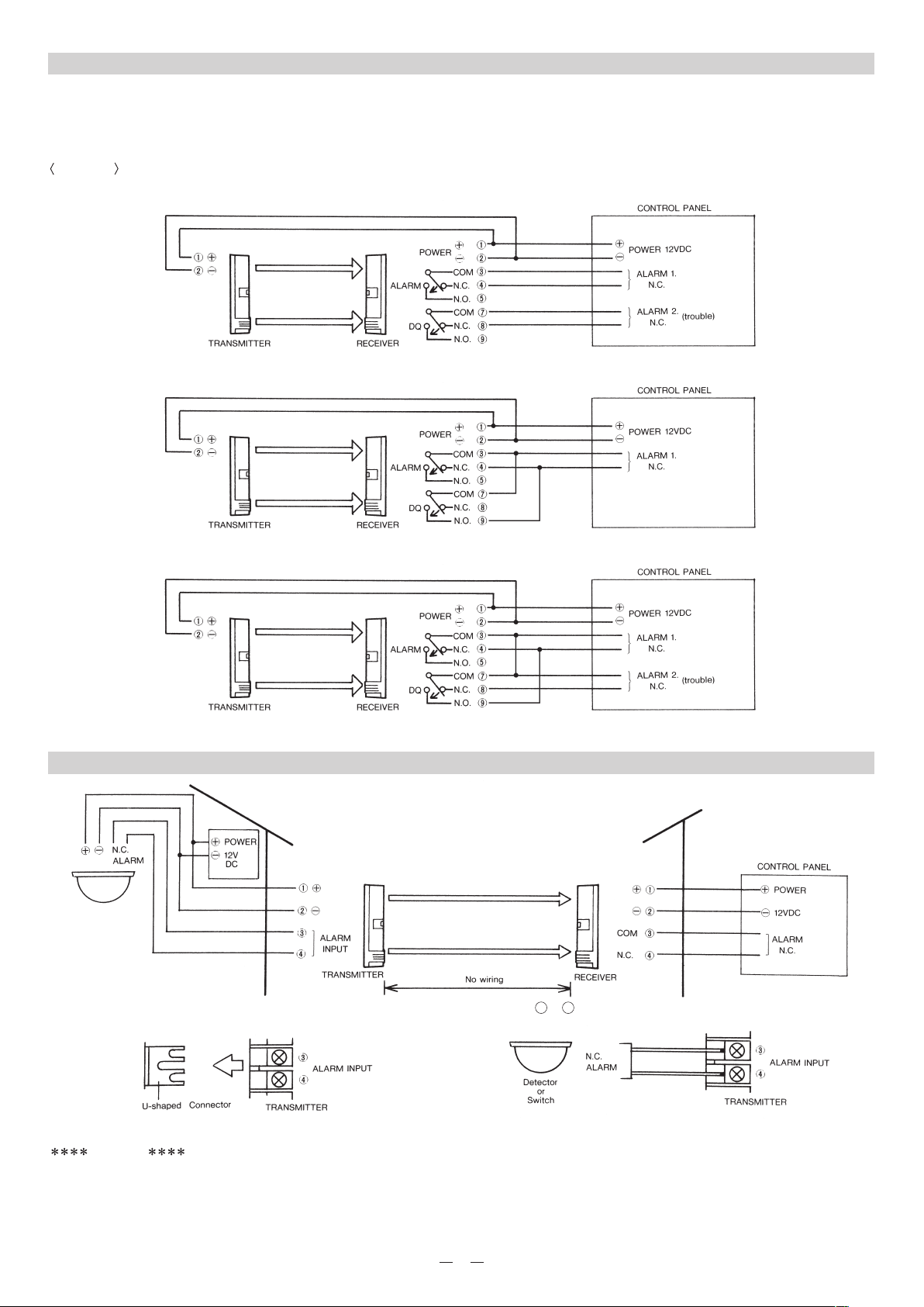
7-3. DQ CIRCUIT (ENVIRONMENTAL DISQUALIFICATION)
D.Q. will send a trouble signal when the beam strength is below an acceptable level due to heavy fog, rain, snow or other changes in
the installation site. The trouble signal output continues as long as the beam strength is below an acceptable level. It will reset when the
environmental conditions clear.
EXAMPLE
A. Trouble Output + Alarm Output
B. Bypasses Alarm
C. Bypasses Alarm + Trouble Output
NOTE : If the control panel's input terminals have the same common, the alarm output, sleep and trouble output can be triggered simultaneously.
7-4. RE-TRANSMITTING CIRCUIT
• The advantage of this method is elimination of wiring from a detector or switch, back to the control panel.
3
• Remove the jumper (U shaped connector) from the transmitter's alarm input terminals (
CAUTION
◦Make sure you connect the jumper (U shaped connector) when the retransmitting circuit is not in use.
◦Output of the detector or switch must be N.C. (N.O. is not acceptable.)
4
&
) and connect the N.C. output of the detector or switch.
9
Page 10
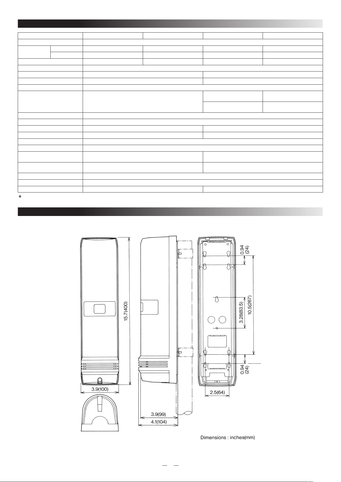
8. SPECIFICATIONS
MODEL AX-250PLUS AX-500PLUS AX-350TF AX-650TF
Detection Method Infrared Photoelectric
Range
Maximum Arrival Distance 2500ft(750m) 5000ft(1500m) 3500ft(1000m) 6500ft(2000m)
Beam Characteristics Pulsed Infrared
Selectable Beam Frequency
Interruption Period 50~500 msec (Selectable) 50, 100, 250, 500 msec (4steps)
Power Input 10.5~30VDC
Current Draw
(transmitter + receiver)
Alarm Period 2sec(±1) nominal
Alarm Output Form C Relay (28VDC 0.2A max)
Tamper Switch
Operating Temperature -13°F~131°F (-25°C~+55°C) -30°F~140°F (-35°C~+60°C)
Environment Humidity 95% max
Alignment Angle ±10° Vertical, ±90° Horizontal
Alarm Memory
Environmental Disqualification
Circuit
Mounting Wall or Pole
Weatherproof IP54
Weight 95.2 oz (2700g) Transmitter and Receiver 97.0 oz (2750g) Transmitter and Receiver
Specifications and design are subject to change without prior notice.
Outdoor 250ft(75m) 500ft(150m) 350ft(100m) 650ft(200m)
Indoor 500ft(150m) 1000ft(300m) 700ft(200m) 1300ft(400m)
—
Normal operation 60 mA max
Normal operation 50 mA max
T:22mA+R:28mA
N.C. opens when cover is removed (RECEIVER only) N.C. opens when cover is removed
—
—
T:11mA+R:49mA
During optical alignment 78 mA max
T:11mA+R:67mA
LED indicates memory status.
Selectable Negative & Positive
Form C relay operates when beam energy has been
gradually reduced to abnormal level.
4 channel
Normal operation 62 mA max
T:13mA+R:49mA
During optical alignment 80 mA max
T:13mA+R:67mA
9. DIMENSIONS
10
Page 11
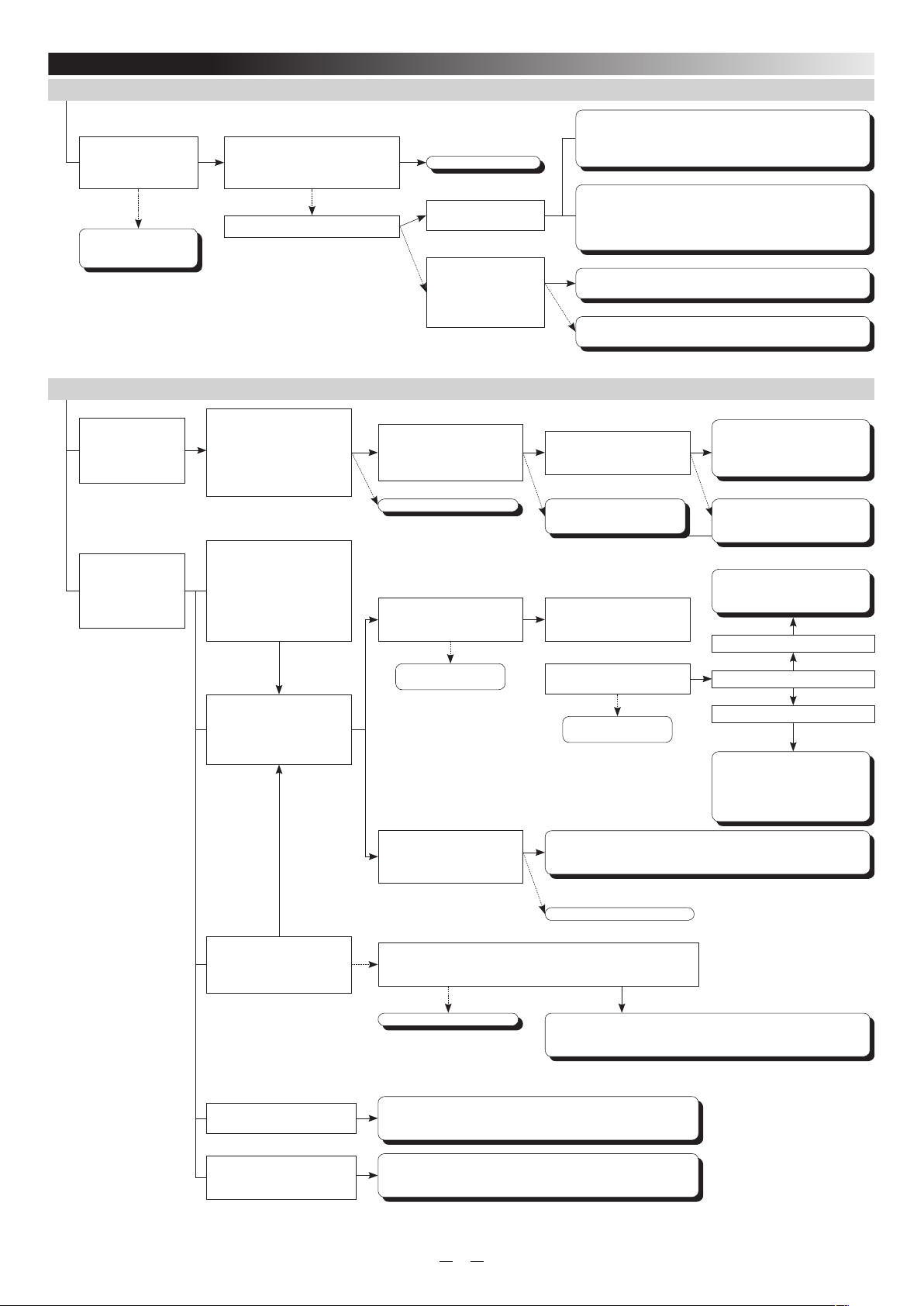
10. TROUBLE SHOOTING CHECK SHEET for AX-250PLUS/500PLUS/350TF/650TF
1. “No Action” on the TRANSMITTER or RECEIVER after power has been applied.
Disconnect power cable from the power supply and the
Photoelectric beam and test for short or open circuit. Also test for
Check to see that
power cables are
properly connected and
polarity is correct.
NG
Correct terminal
connection and/or polarity.
OK OK
Check to see that input power is
within the product's requirements.
AX-250PLUS/500PLUS:10.5-30VDC
AX-350TF/650TF:10.5-30VDC
NG
Does the power supply output more
than 12VDC?
YES
NO
Call Technical Support.
There is a possibility that
the power line has been cut.
Remove the power wires
from Power supply's output
terminals.
Measure the voltage. Does
the power now satisfy the
requirement?
2. “No Action” on alarm zone even though the beams are completely blocked.
short circuit to ground.
Repair as required.
Power cables may be too long for the gauge being used. This will
cause the voltage to drop. Use heavier cable or use additional
power supplies closer to the farthest units. If you are unsure of the
proper wire gauge, call Technical Support.
YES
The power line is short circuited or grounded.
Repair as required.
The power supply may be malfunctioning, repair is required, or
call power supply manufacturer.
NO
Alarm Indicator LED
lights but control
panel does not
recognize the alarm
signal.
When the
RECEIVER'S cover
is removed and the
beams are blocked,
the Alarm Indicator
LED does not light.
Remove the alarm circuit
wires from the RECEIVER.
Check the action of the alarm
output relay. Does the relay
open when the LED Indicator
activates?
If the beam is interrupted
at a location far from the
RECEIVER, no alarm signal
is generated, but when the
beam is interrupted at a
location near the RECEIVER,
an alarm signal generated.
The RECEIVER may be
affected by other beam
TRANSMITTERS, or the
beams are being reflected off
of a shiny surface.
OK
OK
Remove the alarm circuit wire
from the RECEIVER, and
check for short circuits on the
wires.
NG
Call Technical Support.
Are there any other outdoor
beams near the installation
site?
Check other items.
Are there any surface
between the TRANSMITTER
and RECEIVER that are
reflecting the beam?
NO
OK
Is the control panel zone's
“Loop Response Time" set to
within 1 second?
NG
Re-wiring of the alarm circuit
wire is required. Replace or
repair as necessary
YES
Remove power from all other
TRANSMITTERS and conduct
walk test.
Does the Photoelectric Beam
work properly?
NO
Check other items.
YES
Adjust vertical and/or horizontal alignment in order to move the
IR energy off the reflective surface. Monitor the beam strength
(Monitor Jack) while adjusting beam to insure stable alignment.
OK
The control panel may be
malfunctioning, call the control
panel manufacturer.
NG
Re-program the Zone's “Loop
Response Time" appropriately.
“Change the lay-out of the beams
or call Technical Support for
further advice."
AX-250PLUS/500PLUS
YES
Which AX is used?
AX-350TF/650TF
If AX-350TF/AX-650TF beams are
used at the installation site, select
different “Frequency Channels"
for the beams causing the
interference.
When the mirrors of the
RECEIVER are completely
covered, an alarm signal is
generated.
The beam interruption time is
set too long.
The intended target does not
block both upper and lower
beams completely.
NO
Check other items.
Remove the alarm circuit wire from the RECEIVER, place your volt
NG
meter on resistance and measure the alarm output relay. Does the
relay open when power is removed?
YESNO
Call Technical Support.
Turn the interruption time adjustment dial counter-clockwise one
graduation.
Does the RECEIVER work when both upper and lower beams are
completely blocked? If so, the installation height is not proper.
Adjust the installation height.
The unit may be affected by electrical noise. May need to use
shielded wire and/or metalic conduit pipe. Call Technical Support
if you are unsure of the proper shielding techniques.
11
Page 12
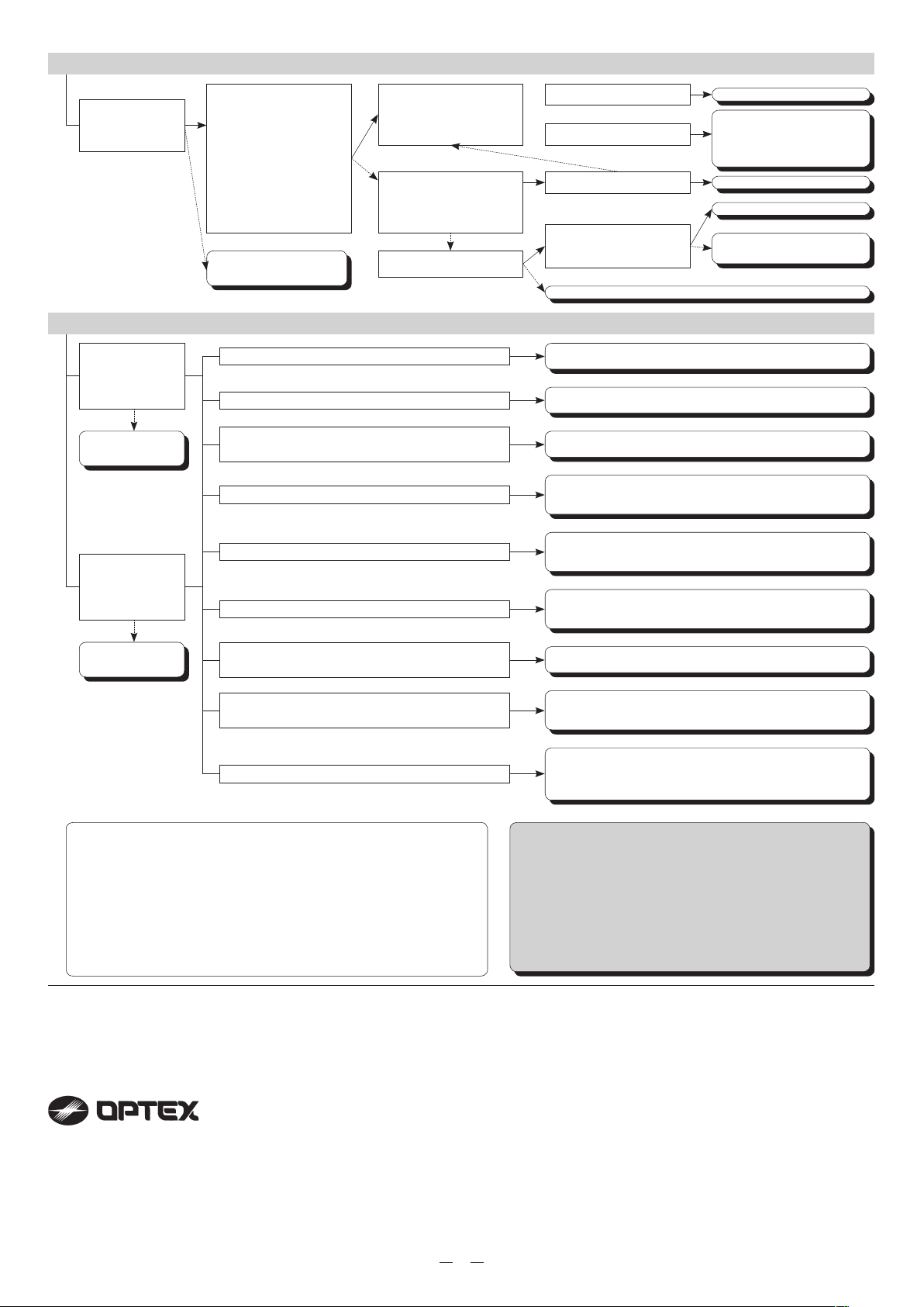
3. Alarm signal is being generated though beams are not blocked
Is the Alarm
Indicator LED on
the RECEIVER
illuminated?
4. False activations
Check alignment
voltage from Monitor
Jack. Does it
satisfy the minimum
requirement?
NG
“Re-align the beams
Refer to the “Beam
Alignment Procedure.”
Are the beams
mounted on a stable
footing with little
movement of the
mounting structure?
NG
Change footing, pole
or structure to insure a
stable mounting surface.
“Refer to the following “Monitor
YES
Jack Output" valnes to insure the
beams are properly aligned."
AX-250PLUS/500PLUS:5.0 VDC
or more AX-350TF/650TF:5.5
VDC or more
Note:
When using the LED alignment
indicator of the AX-350TF/650TF,
make sure the LED shows
“EXCEL".
NO
Go to page 11, see trouble
shooting procedure number 1.
There is frost or snow on the unit's cover.
OK
Very heavy rain occurred at the same time as the activation.
There are plants, trees or debris that may block the beam
during windy conditions.
The unit may be detecting a large bird.
The units may be detecting small animals (dog, cat, deer etc...)
OK
The RECEIVER is facing directly at the rising or setting sun.
There are reflective objects within 3 feets of beams path. (cars,
glass, surfaces with high gloss paints etc.)
Remove the alarm circuit wire
OK
from the RECEIVER, then
check the alarm output relay
with volt meter.
“Re-align the beams using a
volt meter to insure proper
NG
monitor jack output voltage.
Does the value satisfy the
beams requirement?"
Is the LED indicator on the
TRANSMITTER on?
NO
Output is in alarm condition.
Output is in the normal
condition.
YES
Does the Unit work properly?
Double check to see that
YES
there are no objects that may
be blocking the beams.
Go to page 11, see trouble shooting procedure number 1.
NO
Use the HU-1 heater unit.
“Turn the beam's interruption adjustment clockwise one graduation."
Cut off branches, now grass or secure debris to avoid
unnecessary activation. Or move the beams.
Adjust the interruption time, change the installation height or
move the beams in order to avoid perching birds within the
beam's path.
Adjust the interruption time, change the installation height or
move the beams in order to avoid small animals crossing the
beam's path.
Move the beams to avoid the rising or setting sun. Or swap
TRANSMITTER and RECEIVER locations.
Call Technical Support for other options.
Remove the objects causing the reflection, or move the beams.
Call Technical Support for other options.
NG
Call Technical Support.
Check the alarm circuit wires
for shorts, opens or grounds.
Also check the control panel
for proper function.
OK
Completed.
Call Technical Support.
OK
Remove any objects or move
the beams.
NG
Bad wiring or corroded splices. Check for shorts, opens,
grounds and high resistance on the alarm circuit wires.
The covers are very dirty or dusty.
Check for shorts, opens grounds and high resistance values or
the alarm circuit wires. If everything looks to be OK, call Technical
Support for further testing measures.
Clean covers both inside and outside using a dry soft cloth or
mild soap and water only. Do not use any oil or alcohol based
solvents to clean the covers, doing so will cloud or etch the cover
and reduce its efficiency.
Note: Beam Alignment Procedure
When aligning dual or twin beams you must cover both bottom receiver mirror and
transmitter mirror with blocking shields, than adjust the top attempting to maximize
the Monitor Jack Voltage (see below). When maximum voltage is obtained,
place the blocking shields on both upper receiver mirror and transmitter mirror
and adjust lower for maximum Monitor Jack Voltage. (Do not align both beams
simultaneously.)
AX-250PLUS/500PLUS:5.0VDC or more
AX-350TF/650TF:5.5VDC or more
When using LED INDICATOR of AX-350TF/650TF, align to get at least “EXCEL".
The majority of false activations can be attributed to
poor beam alignment. When aligning outdoor beams
accept no less than an “EXCEL" value for the most
stable and trouble free system!! Refer to the installation
manual for acceptable Monitor Jack Voltage Values.
Important:
NOTE
This unit is designed to detect an intruder and activate an alarm control panel. Being only a part of a complete system, we cannot accept resposibility
for any damages or other consequences resulting from an intrusion.
These units are designed to detect an intruder and activate an alarm control panel. Being only a part of a complete system, we cannot accept
responsibility for any damages or other consequences resulting from an intrusion.
These products conform to the EMC Directive 89/336 ECC.
OPTEX CO., LTD.
(JAPAN)
(ISO 9001 Certified by LRQA)
(ISO 14001 Certified by JET)
5-8-12 Ogoto
Otsu, Shiga, 520-0101
Japan
Tel:+81-77-579-8670
Fax:+81-77-579-8190
http://www.optex.co.jp/e
OPTEX INCORPORATED
(USA)
13661 Benson Ave., Bldg.
C.Chino,
CA 91710 U.S.A.
Tel:+1-909-993-5770
Fax:+1-909-628-5560
http://www.optexamerica.com
OPTEX(EUROPE)LTD.
(UK)
(ISO 9001 Certified by NQA)
Clivemont Road, Maidenhead,
Berkshire, SL6 7BU
UK
Tel:+44-1628-631000
fax:+44-1628-636311
http://www.optexeurope.com
OPTEX SECURITY SAS
(FRANCE)
Batiment Sis 475, Rue Piani
69480
Amberieux d'Azergues, France
Tel:+33-437-55-50-50
Fax:+33-437-55-50-59
http://www.optex-security.com
OPTEX KOREA CO., LTD.
(KOREA)
1001 Sambu RenaissanceTower 456,
Kongduck-Dong, Mapo-Gu,
Seoul Korea
Tel:+82-2-719-5971
Fax:+82-2-719-5973
http://www.optexkorea.com
OPTEX SECURITY SP.Z O.O.
(POLAND)
ul.Bitwy Warszawskiej 1920
r.7B,02-366
Warszawa, Poland
Tel:+48-22-598-06-60
Fax:+48-22-598-06-61
12
 Loading...