

Optex AX-100TF Specsheet
SPECIFICATIONS
SHORT RANGE PHOTOELECTRIC DETECTOR
Model
Detection method
Maximum detection range
Maximum arrival range
Interruption period
Selectable beam frequency
Power supply
Current consumption (transmitter + receiver
Alarm period 2sec. (±1) nominal
Alarm output
D.Q. output
Tamper switch
Operating temperature
Operating humidity
Alignment angle
Mounting
Weight (transmitter + receiver
Housing protection (EN00529
*Specifications and design are subject to change without prior notice.
NOTE: These units are designed to detect an intruder and activate an alarm control panel. Being only a part of a complete system, we cannot accept responsibility for any damages or
other consequences resulting from an intrusion. These products conform to the EMC Directive 89/336 ECC.
)
)
AX-70TN AX-130TN AX-200TN AX-100TF AX-200TF
Infrared beam interruption detection
)
20m (70ft.
200m (700ft.
38mA (max.
)
)
)
Use the optional heating unit (HU-3) in conditions of -25°C (-13°F) or below.
40m (130ft.
400m (1300ft.
Selectable between 50, 100, 250, and 500m sec.
41mA (max.
N.C. 28V DC, 0.2A (max.
Opens when cover is removed at 28V DC, 0.2A max.
650g (22.9oz.)
)
)
-35°C to +60°C (-31°F to +140°F
± 90° Horizontal, ± 5° Vertical
60m (200ft.
)
600m (2000ft.
10.5 - 28V DC
45mA (max.
)
95% max.
Wall and pole mounting
IP65
)
)
)
30m (100ft.
300m (1000ft.
44mA (max.
N.C./N.O. 28V DC, 0.2A (max.
)
)
)
4 channel
)
N.C. 28V DC, 0.2A (max.
700g (24.7oz.)
60m (200ft.
600m (2000ft.
48mA (max.
)
)
)
)
)
AX-70/130/200TN
(
STANDARD MODEL
AX-100
(
ENHANCED MODEL
/
200TF
)
)
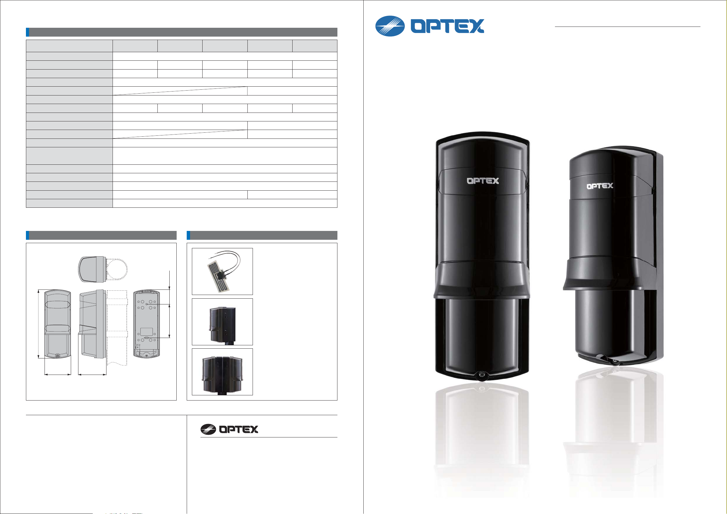
DIMENSIONS OPTIONS
)
1.4
(
36
)
6.7
(
170
65 (2.6
)
69.5 (2.7
)
Dimensions : mm (inches
)
3.3
(
83.5
)
■ HU-3 : Heating Unit
Heating unit for severe low
temperature conditions
24V DC/AC, 420mA max.
1 set (2 units
)
■ BC-3 : Back Cover
Can be used to cover
mounting pole.
1 set (2 units
)
■ PSC-3 : Pole Side Cover
Cover for installing
2 units to 1 pole.
1 set (2 units
)
OPTEX CO., LTD.
(
ISO 9001 Certified by LRQA / ISO14001 Certified by JET
5-8-12 Ogoto, Otsu, Shiga, 520-0101 Japan
TEL +81(0)77 579 8670 FAX +81(0)77 579 8190
OPTEX INCORPORATED (USA
OPTEX (EUROPE) LTD. (UK
OPTEX SECURITY SAS (FRANCE
OPTEX KOREA CO., LTD. (KOREA
OPTEX SECURITY Sp. z o.o. (POLAND
)
)
)
)
)
http://www.optex.co.jp/e
http://www.optexamerica.com
http://www.optexeurope.com
http://www.optex-security.com
http://www.optexkorea.com
)
No. 75107-00-909-0612“Take Care of the Environment” This catalogue uses recycled paper
The Best Short Range Photoelectric Detector
AX-TN/TF series is a compact photoelectric detector with "the IP65 high durability", and
"stable detection performance".
These features reduce false alarms drastically caused by outdoor severe environmental changes and
provide a wide range of applications.
The best short range photoelectric
SHORT RANGE PHOTOELECTRIC DETECTOR
(
AX-70/130/200TN
AX-100/200TF
STANDARD MODEL
(
ENHANCED MODEL
)
)
detector from OPTEX
□ IP65 structure with high sealing rubber packing
Rubber packing is used for all
conceivable points where water or
dust may penetrate, such as wiring
holes, wire ports and the outer
chassis. Prevention from dust, bugs
and water delivers performance with
higher reliability against false alarms
and breakdowns.
IP65
Waterproof.
Protected against water jets from
any direction
Dust-tight.
No ingress of dust.
International Protection Code.
It shows the degress of protection
provided by enclosures.
5 degrees of water conditions were
used to evaluate the protection
against water
Tests were conducted using a water
jet stream that applied 12.5
liters/min of water at a distance of
approximately 3 meters for roughly 3
minutes. This test was directly
applied to the chassis of the AX-TN
and TF series.
The tests resulted with the AX-TN/TF
unit undamaged due to the highly
durable IP65 rated structure. It aids
in the prevention of water damage to
the unit while keeping the detector
operating accurately in outdoor
environments.
Rubber
packing
Wiring
hole
□ Anti-frost hood cover
A hood is installed to prevent frost forming on lower beams. It also makes
the maintenance easy because the surface of the cover is flat.
□ Lightning protection
An improved Electro-Magnetic Interference surge absorber and high
surge resistive relay has been installed to protect from lightning surges
and maintain stable operation.
Lightning Protection Level
Conventional
Detector
AX Series
2 4 6 8 10 12 140
Lightning Surge Voltage Level
Will remain stable against over
14kV of lightning surge.
(kV)
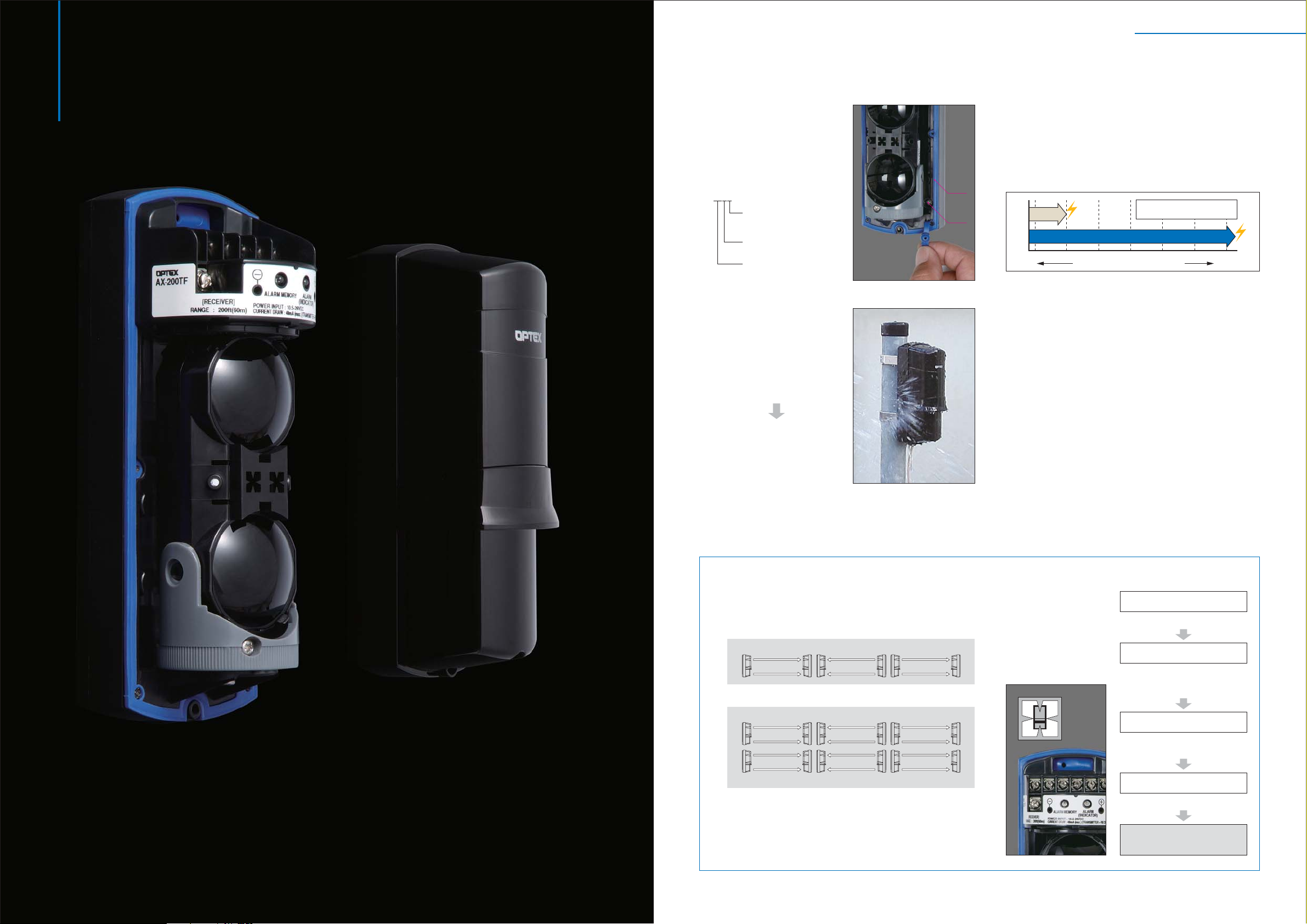
□ Easy angle adjustment
It allows the installer to finely adjust the beam easily.
[ Horizontally ±90° with hand ]
[ Vertically ±5° with screwdriver ]
□ High grade spherical lens
The high grade spherical lens creates more sharply defined & precise
infrared beams compared to ordinary fresnel lenses.
□ A.G.C. (Automatic Gain Control) Circuit
A.G.C. circuit continually monitors for gradual changes in the signal's strength
caused by changing weather conditions. It adjusts the sensitivity accordingly
to maintain the proper signal level for the current environmental conditions.
□ 99% beam blocking stability
Enables stable operation with as much as 99% loss of beam energy
caused by heavy rain, dust storms, fog or snow.
□ Adjustable beam interruption period
The beam interruption time can be adjusted to fit any application. For
example, when protecting a wall or fence, a longer interruption time will
catch intruders.
OPTEX succeeded to strengthen the basic performance and ability of photoelectric detector to reduce false alarms
under severe outdoor environments.
The rubber packing for wiring hole prevents rain, dust, and tiny insects from getting into the unit and the widely
designed optical pitch maximizes the detection principle of twin beam.
AX-100/200TF only
□ Selectable beam frequencies
The selectable beam frequencies can be used to avoid unwanted
crosstalk that can occur when using multiple photobeams for long
distance or beam stacking applications.
1. Long distance stacking
TRANSMITTER RECEIVER TRANSMITTERRECEIVER TRANSMITTER RECEIVER
Ch1 Ch1 Ch1 Ch1 Ch3
2. Two beam long distance
TRANSMITTER RECEIVER RECEIVER TRANSMITTER TRANSMITTER RECEIVER
Ch1 Ch1
Ch3 Ch3
TRANSMITTER RECEIVER RECEIVER TRANSMITTER TRANSMITTER RECEIVER
□ D.Q. Circuit
D.Q. circuit (environmental disqualification) sends a trouble signal when
the beam strength is below and acceptable level due to heavy fog, rain,
snow or other changes in the installation site. The trouble signal output
continues as long as the beam strength is below an acceptable level.
Ch1 Ch1
Ch3 Ch3
Ch2
Ch4
Ch3
Ch2
Ch4
□
4 step alarm indicator LED for fast & accurate optical alignment
The alignment condition
is visually displayed on
the LED. It shows the
alignment condition by
using 4different process
to achieve accurate and
easy alignment before
finetuning.
LED is "ON"
Before alignment.
LED is "Fast Flickering"
Under the beam alignment.
LED indication changes by
beam receiving level.
LED is "Slow Flickering"
Beam energy fromtransmitter is
reaching receiver.
LED is "OFF"
Ready for fine tuning
Fine Adjustment
with voltmeter
 Loading...