

Optelecom VBS 2020 TX, VBS 2050 TX User Manual
VBS 2020 TX and VBS 2050 TX
Stand-alone optical video transmitters
USER MANUAL
1. General Description
An optical video baseband transmitter VBS 2020 or
2050 TX will convert an electrical composite video
signal into an optical, intensity modulated
equivalent, using AM techniques. The VBS 2020
TX uses an optical wavelength of 850 nm and
needs a multimode optical fibre connection, while
the VBS 2050 TX transmits at 1300 nm and will
work with single-mode or multimode fibre. In the
latter case, at least 10 dB link attenuation is
required.
VBS 2020 TX and 2050 TX stand-alone transmitters are designed for use in combination with
Optelecom-NKF optical receiver modules from the
VBS 2000 series, i.e. the VBS 2010/2020 and VBS
2040/2050 single and triple receivers, respectively.
The units may be powered with Optelecom-NKF's
PSA 12 DC power supply; for applications in harsh
environments, a PSU 12 DC is recommended.
Other technical specifications are listed in section 4.
2. Indicators and connectors
Figure 1 shows the signal connection facilities and
the indicator on the signal I/O side of a VBS standalone transmitter. The green LED (2) signals
POWER ON. The optical output has an ST
connector (1), while a 75 Ω BNC connector (3) is
used for input.
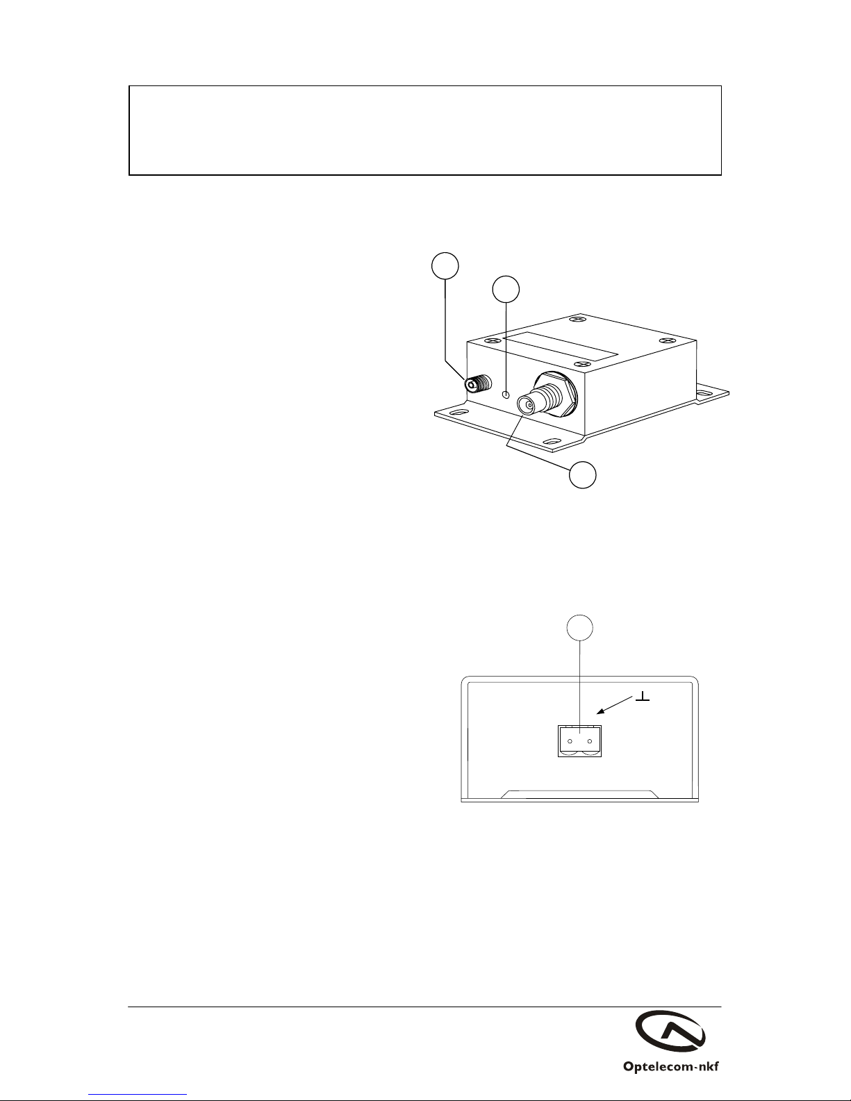
The other side of the unit carries a DC power
connector (4, see figure 2). The negative terminal is
tied to the housing.
3. Installation and maintenance
In some cases, the unit can be fitted inside a camera
housing. Please use the correct power supply
voltage (see section 4, Technical Specifications).
In order to maintain reliable operation of the
module, please observe the following:
- Prevent dust from collecting on the unit
- Protect the module against moisture.
If the output from an optical connection fed by this
module is too low, please check the optical link
first.
Safety and EMC information will be found in the
final section of this document.
2
1
3
Figure 2.
Stand-alone transmitter VBS 2020 or 2050 TX, with
DC power connector. Please note that the negative
terminal is tied to the housing
Figure 1.
Stand-alone transmitter VBS 2020 or 2050 TX,
perspective view. See section 2 for explanation.
+
_
4

2
4. Technical specifications
VBS 2020 TX VBS 2050 TX
Optical
Wavelength 850 1300 nm
Source LED LED
Fibre type 62.5, 50
62.5
(1)
, 50
(1)
, 9
μm
Output level
≥-18, ≥-22
≥-28
(2)
dBm
Power budget
(3)
18, 14 12
(2)
dB
Video (with corresponding VBS RX)
Video system PAL/SECAM/NTSC
Bandwidth (-3 dB) 10 MHz
Differential gain 5 %
Differential phase 5
o
Input impedance 75
Ω
Input level 1 (±3 dB) Vpp
Electrical
Power supply voltage 12 ± 1 VDC
Current consumption 45 65 mA
Environmental
Ambient temperature
Full performance +5 to +45
o
C
Operation -30 to +70
o
C
Relative humidity <95 (no condensation) %
Electrical safety AL / IEC / EN 60950-1
UL recognition file E242498
Laser safety IEC 60825-1, IEC 60825-2
EMC immunity
EN 55024, EN 50130-4,
EN 61000-6-2
EMC emission EN 55022 (Class B)
FCC 47 CFR 15 (Class B)
Mechanical
Outer dimensions 32.5 x 60 x 90 mm
Weight 0.140 kg
Optical connector ST
Video connector BNC
Power connector Combicon (2-pin)
1
Certain restrictions apply, see section 1
2
Into 9 μm fibre
3
With matching VBS receivers
Table 1. Technical specifications of stand-alone
optical transmitters VBS 2020 TX and 2050 TX
5. Safety, EMC, ESD
General
The safety information contained in this section, and on
other pages of this manual, must be observed whenever this
unit is operated, serviced, or repaired. Failure to comply with
any precaution, warning, or instruction noted in the manual
is in violation of the standards of design, manufacture, and
intended use of the unit.
Installation, adjustment, maintenance and repair of this
equipment are to be performed by trained personnel aware of
the hazards involved. For correct and safe use of the
equipment and in order to keep the equipment in a safe
condition, it is essential that both operating and servicing
personnel follow standard safety procedures in addition to the
safety precautions and warnings specified in this manual, and
that this unit be installed in locations accessible to trained
service personnel only.
Optelecom-NKF assumes no liability for the customer’s
failure to comply with any of these safety requirements.
UL/IEC/EN 60950-1: General safety requirements
The equipment described in this manual has been
designed and tested according to the UL/IEC/EN 60950-1
safety requirements.
If there is any doubt regarding the safety of the equipment, do
not put it into operation. This might be the case when the
equipment shows physical damage or is stressed beyond
tolerable limits (e.g. during storage and transportation).
Before opening the equipment, disconnect it from all power
sources. The equipment must be powered by a SELV
*)
power
supply.
When this unit is operated in extremely elevated temperature
conditions, it is possible for internal and external metal
surfaces to become extremely hot.
Optical safety
This optical equipment contains Class 1M lasers or LEDs
and has been designed and tested to meet IEC 608251:1993+A1+A2 and IEC 60825-2:2004 safety class 1M
requirements.
Optical equipment presents potential hazards to testing and
servicing personnel owing to high levels of optical radiation.
When using magnifying optical instruments, avoid looking
directly into the output of an operating transmitter or into the
end of a fibre connected to an operating transmitter, or there
will be a risk of permanent eye damage. Precautions should
be taken to prevent exposure to optical radiation when the
unit is removed from its enclosure or when the fiber is
disconnected from the unit. The optical radiation is invisible
to the eye.
Use of controls or adjustments or procedures other than
those specified herein may result in hazardous radiation
exposure.
The installer is responsible for ensuring that the label
depicted below (background: yellow; border and text: black)
is present in the restricted locations where this equipment is
installed.
The locations of all optical connections are listed in the
Indications and Connectors section of this manual.
Hazard Level 1M
 Loading...