

Optelecom 9525AY/SM-FC, 9525AY, 9525AY/SM-ST Installation And Operation Manual

Model 9525AY
Single Fiber Dual Optics RS232, RS422, or
RS485 Drop and Insert Modem
Optelecom 9000 Series
Installation and Operation Manual
UM50236, Manual 9525AY, Rev. B


Table of Contents
Section Page
Safety Instructions 4
1 - INTRODUCTION 5
1.1 General description 5
1.2 Physical Specification 6
1.3 Environmental Specification 6
1.4 Functional Specifications 6
2 - INSTALLATION 9
2.1 System Architecture 9
2.2 Modes of Operation 13
2.3 Operational Features and Considerations 15
2.4 Set-Up Procedures 18
2.5 Mounting 19
2.6 Optical Cabling 20
2.7 Electrical Cabling 21
2.8 Power Wiring 23
3 - OPERATION 24
3.1 Turn on Procedure 24
3.2 Indicator Light Interpretation 24
3
Safety Instructions
DANGER
Invisible Laser Radiation
When Open AVOID DIRECT
EXPOSURE TO BEAM.
NOTE 1 THIS PRODUCT CONTAINS A CLASS 1 LASER OR LED FIBER OPTIC EMITTER. THE FOLLOWING
SAFETY PRECAUTIONS APPLY.
WARNING: Do not disconnect the fiber optic connector while the unit is powered up. Exposure to Class I
invisible optical radiation is possible when the internal fiber optic connector is disconnected while the unit is
powered up.
All Laser versions have one of two DANGER labels, shown below, found on the front panel and on the edge of
the circuit card containing the laser, near the fiber optic connector.
CAUTION: Using controls, making adjustments or performing operations other than those specified may
result in hazardous radiation exposure. Exposure for only seconds may cause permanent eye damage as well
as other injuries.
NOTE 2 This assembly contains parts sensitive to damage by electro-static discharge (ESD). Use ESD
precautionary procedures when touching, removing or inserting parts or assemblies.
4

1 - INTRODUCTION
1.1 General description
The TKH Security USA Model 9525AY is an RS232, RS422, and RS485 compatible standalone fiber optic
modem with dual optics for drop and insert applications that can be configured in a wide range of
poll/response network architectures. The unit operates using only one single mode fiber for transmit and
receive in the upstream direction. A second fiber is used in the downstream direction. This results in the
formation of a single fiber daisy chain or loop.
The units may be operated in either daisy chain or fault tolerant redundant ring architectures. In addition, in
certain modes, an RS232 expansion port on the modem may be connected to a second modem with single or
dual optics to branch the network in one or two additional directions. With this capability a daisy chain
network may be set up with unlimited branches off the main trunk(s). Additionally, unlimited daisy chain
connections may be made branching off of a main fault tolerant dual fiber ring. All signals received via an
optical port and retransmitted via fiber or via the expansion port are re-timed to.01%pulse width accuracy by
a crystal controlled time-base, eliminating pulse width distortion and allowing virtually unlimited repeating.
The units have four switch selectable modes of operation: Daisy Chain Master mode, Daisy Chain Local mode,
Fault Tolerant Master mode, and Fault Tolerant Local mode. See Section 2, Installation, for a complete
description of these modes of operation.
The units have anti-streaming (sometimes referred to as anti-babbling) circuitry for both the optical fiber and
electrical (RS232) sides. On the RS232 side, when enabled, the anti-streaming limits the amount of time a
terminal is allowed to transmit data onto the network for each Request to Send. This is to prevent a faulty
terminal unit from monopolizing the network. On the fiber side the anti-streaming disables an optical receiver
in the event that the receiver output stays high longer than the maximum allowable time. This will prevent the
whole fiber network from being disabled by a continuous "on" failure by receiver or optical emitter. This
feature is not available when in RS422 or RS485 mode because the RTS line is not supported.
The units have nine LED indicators. A POWER indicator that is on solid when operating under primary power
or blinks if operating on battery backup or under low voltage from the primary power source. A FAULT
indicator illuminates in the event of either a fiber side or electrical side anti-streaming timeout. The other six
indicators serve dual functions as selected by the indicator mode switch. In one position the LEDs indicate
electrical side signal activity. In the other position the LEDs indicate fiber port activity as well as the active
fiber input port as chosen by the priority select circuitry.
A ten-position MODE dipswitch allows the user to select one of the four operating modes and optical emitter
test. In addition, an eight-position TIMEOUT dipswitch allows the user to select timeouts for (or disable)the
optical and electrical side anti-streaming, the fiber activity CTS inhibit (RS232 mode) and the electrical Ring
Propagation output disable (RS485, 2-wire operation only).
The unit operates from a 9 to 14 VDC supply. The unit contains a built in battery charger compatible with a 6
volt lead-acid gel cell battery (1.2 Amp-hour to 7 Amp-hour capacity). This battery allows from 6 to 35 hours
of emergency battery backup operation. A screw terminal connector facilitates battery connection.
The 9525AY module is optically compatible with the 9521Y card.
The package is an anodized aluminum extrusion with painted aluminum front and rear panels. An optional
mounting kit is available for mounting in a System 9000 chassis (Model 9000KIT-5).
5
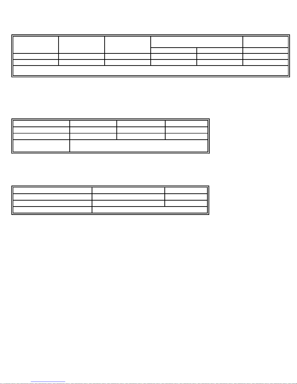
MODELS
OPTIC
PORT
FIBER
Emitter Wavelength
OPTICAL
BUDGET
TX1/RX1
TX2/RX2
9525AY/SM-ST
ST
09/125
1310 nm
1550 nm
26 dB
9525AY/SM-FC
FC
09/125
1310 nm
1550 nm
26dB
1
Range based on 0.5 dB/km at 1310 nm and for 9/125 um fiber. Range includes a 3 dB safety margin.
2
Substitute 9521 for 9525 to order the rack mount card version.
DIMENSIONS
Height
Width
Length
INCHES
1.5
3.17
5.0
WEIGHT
0.81 lb.
0.37 kg
INDICATORS
POWER, TD/TX1, RD/RX1, RTS/TX2, CTS/RX2, TDEXP/RX1
PRIORITY, RDEXP/RX2 PRIORITY, and FAULT.
TEMPERATURE
Fahrenheit
Celsius
Operating
-40 to 165° F
-40 to 74° C
Storage
-40 to 185° F
-40 to 85° C
HUMIDITY
0 to 95% RH noncondensing
Table 1 - Models Available
1.2 Physical Specification
1.3 Environmental Specification
1.4 Functional Specifications
1.4.1 OPTICAL
Wavelength 1310 and 1550 nm
Minimum coupled power into: 9/125 μm -10 dBm Peak
Receiver input power for 19-9 BER:
Minimum -36 dBm peak
Maximum -8 dBm peak
1.4.2 ELECTRICAL (Tx and Rx)
Data Interface RS232, RS422, or RS485 (2- or 4-wire), switch selectable
Connector DB25S (Primary Port)
RJ45 (Expansion Port)
6

1.4.3 SYSTEM PERFORMANCE
Data rates 150, 300, 600, 1.2k, 2.4k, 3.6k, 4.8k, 7.2k, 9.6k, 14.4k,
19.2k, 28.8k, 38.4k, 57.6k, and 115.2k baud (auto baud)
BER 10
Re-timing accuracy 0.02% of pulse width for repeated signals
Electrical anti-streaming timeout selections
DISABLED, 4, 8, 16, 32, and 64 sec
1.4.4 ALARM
Contact Rating 15 VDC @ 15 mA
1.4.5 POWER
Operate 9 to 14 VDC @ 230 mA
Standby 9 to 14 VDC @ 180 mA
-9
Optional 110 VAC Adapter TKH Security USA Model 9014PS
Recommended external battery 6 VDC, 4 Amp hour, PowerSonic Model PS640WL or equal, for up
to 20 hours backup @ 20° C). Battery temperature range is
–20° C to +50° C.
7
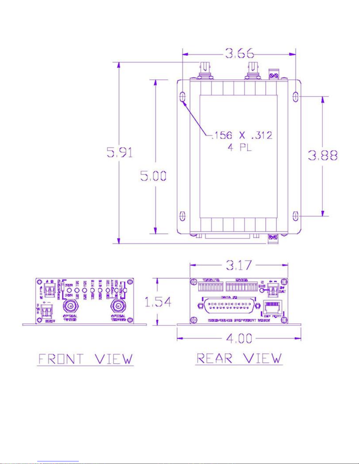
FIGURE 1 — 9525AY DIMENSIONS
8
 Loading...