

Optelecom 9522A Installation And Operation Manual
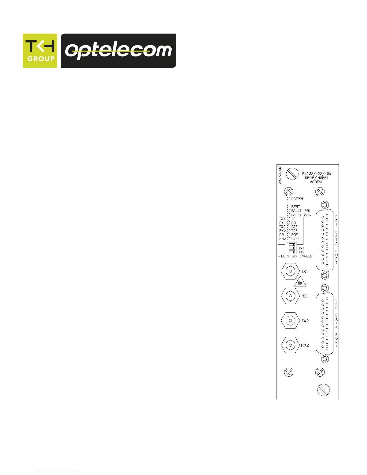
Model 9522A
Two Fiber, Dual Port
Intelligent Drop/Insert Data Modem
9522A modules transport a single RS232/RS422/RS485 data signal in
a daisy chain or redundant loop configuration, making it available on
two separate electrical I/O ports on each unit.
Optelecom 9000 Series
Installation and Operation Manual
UM50392, Manual 9522A, Rev. B


Table of Contents
Section Page
Safety Instructions 4
Instrucciones de Seguridad 5
Sicherheitsanleitungen 6
Consignes de Sécurité 7
Fiber Information 8
Functional Description 9
9522A Front Panel Indicator, Connector, and Switch Locations and Functions 10
9522A Internal Switch Locations and Functions 13
Quick Set Up Guide 14
System Architecture 16
Set Up of the 9522A 27
Operation of the 9522A 34
Operation of the 9522A with the Network Management System (NMS) Software 36
Specifications for the 9522A 37
3

Safety Instructions
The safety information contained in this section, and on other pages of this manual, must be observed whenever this unit is operated,
serviced, or repaired. Failure to comply with any precaution, warning, or instruction noted in the manual is in violation of the standards of
design, manufacture, and intended use of the unit. TKH Security Solutions USA assumes no liability for the customer’s failure to comply
with any of these safety requirements.
RM-1
LASER RADIATION
DO NOT VIEW DIRECTLY WITH OPTICAL INSTRUMENTS (MAGNIFIERS)
CLASS 1M LASER PRODUCT
CAUTION:
DISCONNECTED OPTICAL CONNECTORS MAY EMIT OPTICAL ENERGY.
DO NOT VIEW BEAM WITH OPTICAL INSTRUMENTS (MAGNIFIERS)
This product contains Class 1M lasers or LEDs.
• Class 1M laser product according to IEC60825-1:1993+A1+A2
• CAUTION: Use of controls or adjustments or procedures other than those specified herein may result in hazardous radiation exposure.
• Precautions should be taken to prevent exposure to optical radiation when the unit is removed from its enclosure or when fiber is
disconnected from the unit.
•Laser radiation may be present on a fiber connection to this unit even when the power has been removed from the unit.
•This unit is intended for installation in locations where only trained service personnel have access to the fiber connections.
•The locations of all optical connections are listed in the Connection Locations and Function section of this manual.
•Optical outputs and wavelengths are listed in the Specifications section of this manual.
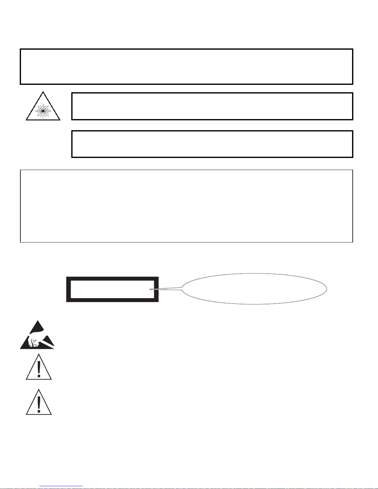
Hazard Level 1M
The border shall be black and
the background shall be yellow
The optical devices used in this equipment are Hazard Level 1M. As required by IEC60825-1, the installer is responsible for insuring that the label
depicted below is present in the restricted locations where this equipment is installed.
This assembly contains parts sensitive to damage by electrostatic discharge (ESD). Use ESD precautionary procedures when
touching, removing, or inserting parts or assemblies.
The chassis into which this unit is installed must be housed in a properly rated NEMA enclosure.
When this unit is operated in extremely elevated temperature conditions, it is possible for internal and external metal surfaces
to become extremely hot. Care should be taken to insure this unit is installed in a restricted area where only properly trained
service personnel have access to the unit.
4
Instrucciones de Seguridad
Debe observarse la información de seguridad contenida en esta sección, y en otras páginas de este manual siempre que se opere, dé
servicio o repare esta unidad. Si no se cumple con alguna precaución, advertencia o instrucción indicada en este manual se infringen los
estándares de diseño, fabricación y el uso destinado a la unidad. TKH Security Solutions USA no asume ninguna responsabilidad si el cliente
no cumple con alguno de estos reequisitos de seguridad.
RM-1
RADIACIÓN LÁSER
NO VER DIRECTAMENTE CON INSTRUMENTOS ÓPTICOS (DE AUMENTO)
PRODUCTO LÁSER CLASE 1M
PRECAUCIÓN:
LOS CONECTORES ÓPTICOS DESCONECTADOS PUEDEN AMITIR ENERGĺA ÓPTICA
NO VER EL HAZ CON INSTRUMENTOS ÓPTICOS (DE AUMENTO)
Este producto contiene rayos láser o diodos emisores de luz Clase 1M.
• Producto láser Clase 1M conforme a la norma IEC60825-1: 1993+A1+A2
•PRECAUCIÓN: El uso de los controles, ajustes o procedimientos, aparte de los aquí especificados, pueden ocasionar exposición peligrosa a la
radiación.
•Deben tomarse precauciones para evitar la exposición a la radiación óptica cuando se saque la unidad de su alojamiento, o cuando se
desconecte la fibra de la unidad
• Puede haber radiación laser en una conexión de fibra a esta unidad aun cuando se haya eliminado la corriente de la unidad.
•Este equipo está destinado a instalarse en lugares donde sólo el personal de servicio debidamente entrenado tenga acceso a las conexiones
de fibra.
•La ubicación de todas las conexiones ópticas se enumeran en la sección Ubicación de los conectores y funciones de este manual.
•Las salidas ópticas y longitudes de onda aparecen en la sección Especificaciones de este manual.
El bordo debe ser negro y
el fondo debe ser amarillo
Nivel de Riesgo 1M
Los dispositivos ópticos usados en este equipo son de Nivel de Riesgo 1M. Según lo exige la norma IEC60825-1, el instalador es responsable de
asegurar que la etiqueta descrita a continuación esté presente en las áreas restringidas donde se instale este equipo.
Este ensamblaje contiene piezas sensibles al daño por descargas electrostáticas (ESD, por sus siglas en inglés). Use
procedimientos para prevenir las descargas electrostáticas al tocar, desmontar o insertar piezas o ensamblajes.
El chasis en el cual está instalada esta unidad debe estar dentro de un alojamiento debidamente calificado por NEMA.
Cuando se opera esta unidad en condiciones de temperatura sumamente elevada, es posible que las superficies internas y
externas de metal se pongan extremadamente calientes. Debe tenerse cuidado para asegurar que esta unidad se instale en un
área restringida donde sólo tenga acceso a la unidad el personal de servicio debidamente capacitado.
5

Sicherheitsanleitungen
Die in diesem Abschnitt und auf anderen seiten dieses Handbuchs enthaltenen Sicherheitsinformationen müssen befolgt werden, wenn
diese Einheit betrieben, gewartet oder repariert wird. Falls Vorsichtsmassnahmen, Warnungen oder Anweisungen in diesem Handbuch
nicht befolgt werden, verstösst dies gegen die Konstruktions, und Herstellungsstandards und erfolgt im gegensatz zum vorgesehenen
Verwendungszweck dieser Einheit. TKH Security Solutions USA übernimmt keine Haftung für das Verabsäumnis des Kunden, diese
Sicherheitsanforderungen einzuhalten.
RM-1
LASER-STRAHLUNG
NICHT DIREKT MIT OPTISCHEN INSTRUMENTEN (LUPEN) ANSEHEN
LASER-PRODUKT DER KLASSE 1M
VORSICHT:
ABGEKLEMMTE OPTISCHE STECKVERBINDER KÖNNEN OPTISCHE ENERGIE FREI SETZEN
NICHT MIT OPTISCHEN INSTRUMENTEN (LUPEN) IN DEN STRAHL BLICKEN.
Dieses Produkt enthält Laser oder LEDs der Klasse 1M.
• Laserprodukt der Klasse 1M gemäß IEC60825-1:1993+a1+A2
• VORSICHT: Wenn die Bedienungselemente anders als hier beschrieben bzw. andere Einstellungen verwendet werden, kann es zu
schädlicher Strahlenaussetzung kommen.
•Es müssen Vorsichtsmaßnahmen getroffen werden, um Aussetzung an optischer Strahlung zu vermeiden, wenn die Einheit aus dem Gehäuse
genommen oder die Faseroptik von der Einheit getrennt wird.
• In einer Faseroptik-Verbindung dieser Einheit kan auch dann Laserstrahlung vorhanden sein, wenn die Stromversorgung zur Einheit
abgeschaltet wurde.
•Diese Einheit ist zum Einbau an Orten vorgesehen, an denen nur geschultes Personal Zugang zu den Faseroptik-Verbindungen hat.
•Die Lage aller optischen Verbindungen ist im Abschnitt über die Lage von Anschlüssen und Funktionsweise dieses Handbuchs zu finden.
•Optsiche Ausgänge und Wellenlängen sind im Abschnitt mit den technischen Daten dieses Handbuchs zu finden.
Gefahrenstufe 1M
Schwarzer Rand und
gelber Hintergrund
Die optischen Vorrichtungen in diesem Gerät haben Gefahrenstufe 1M. Wie vorgeschrieben durch IEC60825-1 ist der Installateur dafür
verantwortlich, sicherzustellen, dass die unten abgebildeten Schilder an den Orten mit eingeschränktem Zugang, an denen dieses Gerät aufgestellt
ist, vorhanden sind.
Diese Baugruppe enthält Teile, die durch elektrostatische Entladungen (ESD) beschädigt werden können. Vorsichtsmaβnahmen
zum Schutz vor elektrostatischer Entladung treffen, wenn Teile oder Baugruppen berührt, ausgebaut oder eingefügt werden.
Das Gestell, in dem diese Einheit eingebaut ist, muss in einem entsprechend klassifizierten NEMA-Schutzgehäuse untergebracht
sein.
Wenn diese Einheit bei besonders hohen Temperaturen betrieben wird, können interne und externe Metallflächen extrem heiβ
werden. Es muss darauf geachtet werden, dass diese Einheit in einem Bereich mit eingeschränktem Zugang aufgestellt wird,
damit nur geschultes Wartungspersonal Zugang zur Einheit hat.
6

Consignes de Sécurité
Les consignes de sécurité contenues dans cette section et dans le reste de ce manuel doivent être respectées a chaque fois que cet appareil
est utilisé ou fait l’objêt d’une maintenance ou d’une réparation. Le non-respect d’une précaution, d’un avertissement ou d’une instruction
figurant dans ce manuel est une violation des normes de conception, fabrication et indication d’usage de l’appareil. TKH Security Solutions
USA n’est pas responsable du non-respect de ces consignes de sécurité par le client.
RM-1
RAYONNEMENT LASER
NE PAS REGARDER DIRECTEMENT AVEC DES INSTRUMENTS OPTIQUES (LOUPES)
PRODUIT LASER DE CLASSE 1M
ATTENTION:
LES CONNECTEURS OPTIQUES DEBRANCHES PEUVENT EMETTRE UNE ENERGIE OPTIQUE.
NE PAS REGARDER LE FAISCEAU AVEC DES INSTRUMENTS OPTIQUES (LOUPES)
Ce produit contient des lasers ou diodes électroluminescentes de classe 1M.
• Produit laser de classe 1M conformément à IEC60825-1:1993+A1+A2
• ATTENTION: L’ utilisation de commandes ou réglages, ou de procedures différentes de celles indiquées ici risque de provoquer une
exposition dangereuse au rayonnement.
• Prendre des précautions pour empêcher une exposition au rayonnement optique lorsque l’ appareil est retiré de son boîtier ou lorsque la
câble optique fibre est débranché de l’ appareil.
•Un rayonnement laser pourra être present dans un câble optique branché sur cet appareil, même une fois l’alimentation coupée.
•Cet appareil est prévu pour une installation à des endroits où seul un personnel de maintenance formé accès aux câbles optiques.
•Les points de branchement de tous les cables optiques sont indiqués à la section Points de branchement et function de ce manuel.
•Les sorties et longueurs d’ onde optiques figurant à la section Caractéristiques techniques de ce manual.
Niveau de danger 1M
La bordure doit être noire et
le fond jaune
Les appareils optiques utilisés dans cet équipement correspondent à un niveau de danger 1M. Comme exigé par la norme IEC60825-1, il incombe à
l’installateur de s’assurer que l’étiquette ci-dessous est présente aux endroits d’accès limité où cet équipement est installé.
Cet ensemble contient des pièces sensibles aux décharges électrostatiques (ESD). Prendre les précautions relatives aux ESD
avant
de toucher, retirer ou insérer des pièces ou des ensembles.
Le châssis dans lequel est installé cet appareil doit être place dans une enceinte NEMA conforme aux spécifications nominales.
Lorsque cet appareil fonctionne à une température ambiante extrêmement élevée, il est possible que les surfaces métalliques
internes et externes deviennent extrêmement chaudes. S’assurer que cet appareil est installé dans une zone dont l’accès est
limité à un personnel de maintenance correctement formé.
7

Fiber Information
This unit was manufactured with attention to fiber cleanliness by TKH Security Solutions USA. Beyond the
optical safety information contained in this manual, the following guidelines should be observed when working
with optical fibers.
The biggest problem is dirt!
It takes very little contamination to cause problems with optical fiber connections; cleanliness is extremely
important to proper operation of optical equipment.
1. Protect optical connectors by leaving the connector covers in place on unused fiber connections and on the
fiber tips themselves.
2. Personnel who remove and replace fibers should be equipped with a fiber cleaning kit. These are
inexpensive and can be obtained from any fiber equipment supply house. If you choose to, you can use
propanol and lint-free tissue to clean fibers.
a. Do not use isopropanol alcohol (typically called rubbing alcohol) mixed with water. This can cause
additional spots. (Caution:
b. Use lintless tissues to clean fibers.
Pure isopropanol is very flammable!
)
c. Clean the fiber with a folded tissue moistened with the propanol, pulling the connector tip across
the tissue, then turn the connector 90 degrees and repeat in a different spot on the tissue.
d. Don’t pull the fiber across and then push it back. This will put the dirt that was cleaned off back on
again.
e. Repeat the process on a dry, folded tissue.
3. When removing fibers,
4. When connecting fibers, pay attention to the bend radius of the fibers. A general rule is to have a 3-inch
(8 cm) bend radius. A bend radius less than 3 inches is an attenuator and can cause optical signal loss.
5. Installers of fiber equipment should be equipped with the equipment manuals and an optical power meter
to measure the optical inputs and outputs in a system. An optical power meter is an inexpensive tool that
can save much time and effort in getting optical communications links up and running. Properly equipped
and trained installers can quickly determine the source of any problems that occur.
always
clean them when replacing them no matter how long you had them off.
8

Functional Description
The TKH Security USA Model 9522A is an RS232, RS422, and RS485 compatible fiber optic standalone modem
with dual electrical I/O ports and dual optics for drop and insert applications that can be configured in a wide
range of poll/response network architectures. The unit operates using only one fiber for transmit and receive
in the upstream direction and a second fiber in the downstream direction. This results in the formation of a
single fiber daisy chain or loop.
The units have four switch-selectable modes of operation: Master Fault Tolerant mode (MFT), Local Fault
Tolerant mode (LFT), Master Daisy Chain mode (MDC), and Local Daisy Chain mode (LDC). See the
Installation section for a complete description of these modes of operation.
Each modem has two full function data I/O ports (Primary and Secondary), allowing it to serve two terminal
units at a single location without the need for a second modem. Each of these ports can also interface with
another modem to establish branches off the main trunks or even off other branches. The modem has a
unique feature in that it is able to tag data originating from it when operating in local mode and separately tag
the data from master and local modems. The result of this feature, which identifies the data source, is that the
master only receives data from the locals and the local only receive the data from the master.
The units have ten LED indicators. Power and various fault and status indicators provide information on the
electrical status of the I/O ports, fiber status, redundant ring status, and other possible conditions. A built-in,
offline Bit Error Rate Test (BERT) with indicator LED can help troubleshoot the system. Six of the indicators
serve dual functions as selected by the SELECT switch. In one position the LEDs indicate electrical side signal
activity and CTS status. In the other position the LEDs indicate fiber port activity as well as the active fiber
input port as chosen by the priority select circuitry.
Dipswitches allow the user to select one of the four operating modes (BERT test enable, the communications
interface for each data I/O port, and the timeouts for the optical and electrical side anti-streaming), the fiber
activity CTS inhibit (RS232 mode), the Priority Select Timeout, the electrical Ring Propagation delay, Echo
Cancel, and the “Data Tagging” selective routing feature. These are explained in the Installation section.
The unit operates on 6VDC supplied from the chassis backplane and is compatible with the Network
Management System software for monitoring and troubleshooting TKH Security USA fiber optic transport
systems.
The 9522A modem is optically compatible with the Models 9526A and 9525A standalone drop/insert modems.
9
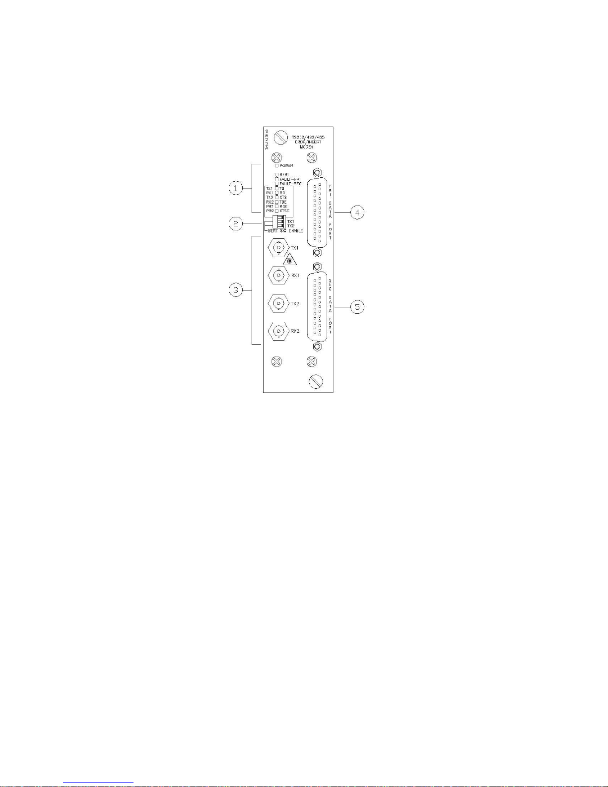
9522A Front Panel Indicator, Connector, and Switch Locations
and Functions
FIGURE 1
1. INDICATORS
Power Indicator: This
the Power Connector on the back of the enclosure.
BERT Indicator: This
another unit, usually the Master unit. NOTE: The rare blinking of this indicator during normal operation
is meaningless and may be ignored.
FAULT — PRI Indicator:
— When operating in Master Fault Tolerant Mode, this
in the redundant loop.
— When operating in one of the two Local Modes, this
Primary Data port has exceeded the electrical anti-streaming timeout period and has been
disabled. In Master Daisy Chain Mode, there are no fault indications.
FAULT — SEC Indicator: This
exceeded the optical or electrical anti-streaming timeout period and has been disabled.
TX1/TD Dual Function Indicator:
—
—
RX1/RD Dual Function Indicator:
—
—
TX1:
When the Indicator Selection Switch is in the left position this
data is being transmitted via the TX1
TD:
When the Indicator Selection Switch is in the right position this
data is detected on the input (Pin 2) of the Primary Data Port.
RX1:
When the Indicator Selection Switch is in the left position this
data is being received via the RX1
RD:
When the Indicator Selection Switch is in the right position this
data is output (on Pin 3) from the Primary Data Port.
green
green
LED illuminates when 8 to 15 VDC power is applied to the modem via
LED illuminates when the unit is properly receiving a BERT signal from
red
LED will illuminate to indicate a break
red
LED will illuminate to indicate that the
red
LED illuminates to indicate that the Secondary Data port has
Optical
Optical
green
Port.
green
green
Port.
green
LED will flash when
LED will flash when
LED will flash when
LED will flash when
10

TX2/CTS Dual Function Indicator:
—
—
RX2/TDE Dual Function Indicator:
—
—
PR1/RDE Dual Function Indicator:
—
—
PR2/CTSE Dual Function Indicator:
—
—
2. FRONT PANEL DIPSWITCH
Indicator Selection Switch (Position 1):
— When in the left position, the Dual Function Indicators are relevant to the signals listed on the
— When in the right position, the Dual Function Indicators are relevant to the signals listed on the
BERT Test Enable Switch, Optical Port TX1 (Position 2): This switch enables the built-in
rudimentary BERT test signal generator and detector for the TX1 Optical Port. To run a BERT test, the
normal electrical input to all the modems in the system must be disconnected or disabled.
BERT Test Enable Switch, Optical Port TX2 (Position 3): This switch enables the built-in
rudimentary BERT test signal generator and detector for the TX2 Optical Port. To run a BERT test, the
normal electrical input to all the modems in the system must be disconnected or disabled.
For details on the built-in BERT test, refer to the Operations section of this manual.
TX2:
When the Indicator Selection Switch is in the left position this
data is being transmitted via the TX2
CTS:
When the Indicator Selection Switch is in the right position this
true CTS output from Pin 5 of the Primary Data Port.
RX2:
When the Indicator Selection Switch is in the left position this
data is being received via the RX2
TDE:
When the Indicator Selection Switch is in the right position this
data is detected on the input (Pin 2) of the Secondary Data Port.
PR1:
When the Indicator Selection Switch is in the left position this
when the RX1
RDE:
When the Indicator Selection Switch is in the right position this
data is output (on Pin 3) from the Secondary Data Port.
PR2:
When the Indicator Selection Switch is in the left position this
when the RX2
RDE:
When the Indicator Selection Switch is in the right position this
data is output (on Pin 3) from the Secondary Data Port.
left side of the indicators.
right side of the indicators.
Optical
Optical
Port is selected by the priority selection circuitry.
Port is selected by the priority selection circuitry.
Optical
Optical
Port.
Port.
green
green
green
green
green
green
green
green
LED will flash when
LED indicates a
LED will flash when
LED will flash when
LED will illuminate
LED will flash when
LED will illuminate
LED will flash when
3. OPTICAL INPUT/OUTPUT PORTS
The TX1 and RX1 pair are the output and input ports for the optical link to/from the next upstream modem.
The TX2 and RX2 pair are the output and input ports for the optical link to/from the next downstream
modem.
4. PRIMARY DATA PORT CONNECTOR
This DB25P connector provides the input/output connections for the RS232, RS422, and RS485 Connections
to the Primary Data Port. Refer to the Set Up section of this manual for more details on using these outputs
and inputs.
11

5. SECONDARY DATA PORT CONNECTOR
This DB25P connector provides the input/output connections for the RS232, RS422, and RS485 Connections
to the Secondary Data Port. Refer to the Set Up section of this manual for more details on using these
outputs and inputs.
12
 Loading...