

Page 1
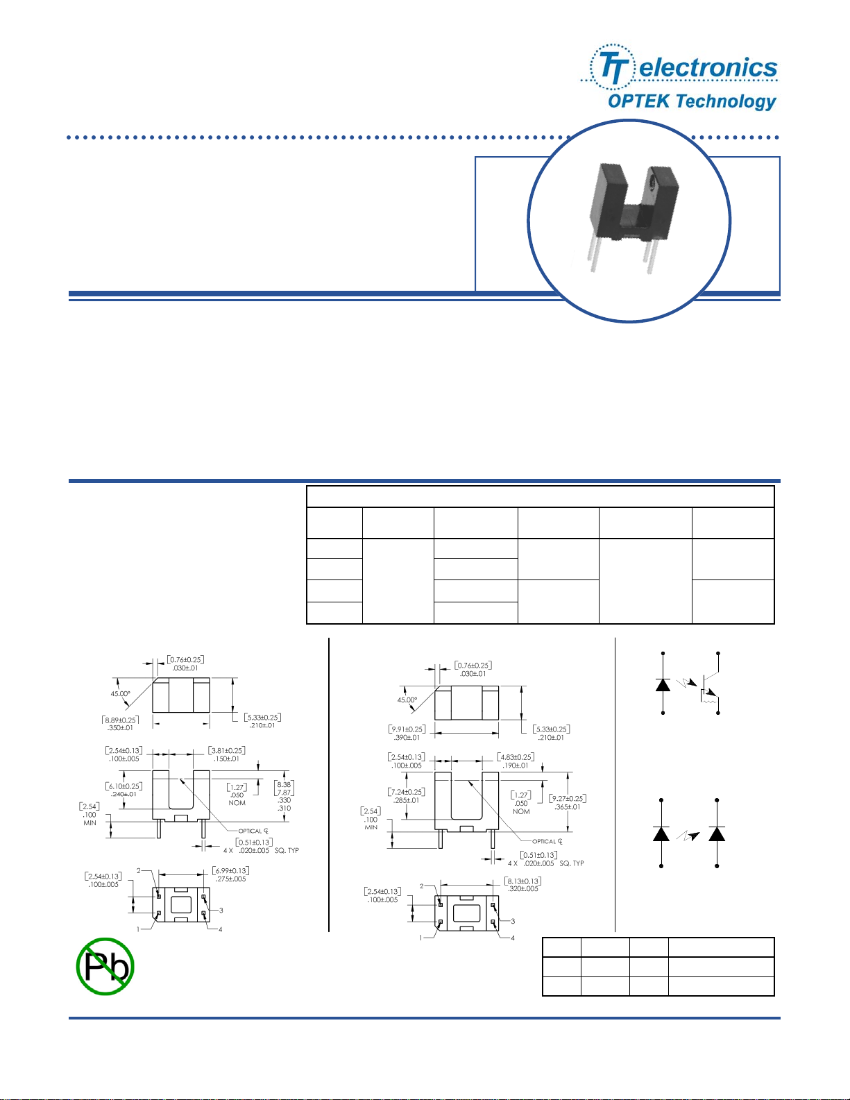
Slotted Optical Switch
OPB610, OPB611, OPB620, OPB621
Features:
• Non-contact switching
• Printed circuit board mounting
• Enhanced signal to noise ratio
• PIN photodiode sensor for high speed (OPB611, OPB621)
• Lead centers: 0.275” (OPB61_ ) / 0.320” (OPB62_ )
• Gap: 0.150” (OPB61_ ) / 0.190” (OPB62_ )
Description:
The OPB610 and OPB620 slotted optical switches consist of an infrared emitting diode and an NPN silicon
phototransistor with an enhanced low current roll-off to improve contrast ratio and immunity to background
irradiance.
The OPB611, OPB621 slotted optical switch consists of an infrared emitting diode and a PIN photodiode with a
polysulfone housing that is opaque to visible light, but transmissive to infrared. The low t
is ideal for high-speed operation. The sensitivity to ambient radiation is minimized.
Custom electrical, wire and cabling and connectors are available. Contact your local representative or OPTEK for
more information.
of the PIN photodiode
r/tf
Applications:
• Non-contact reflective object sensor
• Assembly line automation
• Machine automation
• Machine safety
• End of travel sensor
• Door sensor
OPB610, OPB611
Ordering Information
Part
Number
OPB610
OPB611 Diode
OPB620 Rbe Transistor
OPB621 Diode
LED Peak
Wavelength Sensor
Rbe Transistor
890 nm
OPB620, OPB621
Slot Width /
Depth
0.150" / 0.240”
0.190" / 0.285” 0.100" / 0.320"
Aperture
Emitter / Sensor
0.06” / 0.06”
2
1
OPB610, OPB620
2
1
Lead Length /
Spacing
0.100" / 0.275"
3
4
3
4
[ MILLIMETERS]
DIMENSIONS ARE IN:
INCHES
RoHS
OPTEK Technology Inc. — 1645 Wallace Drive, Carrollton, Texas 75006
Phone: (972) 323-2200 or (800) 341-4747 FAX: (972) 323-2396 [email protected] www.optekinc.com
OPTEK reserves the right to make changes at any time in order to improve design and to supply the best product possible.
Pin # LED Pin # Transistor / Diode
OPB611, OPB621
1 Anode 4 Emitter / Anode
2 Cathode 3 Collector / Cathode
Issue C 02/2012
Page 1 of 4
Page 2
Slotted Optical Switch
OPB610, OPB611, OPB620, OPB621
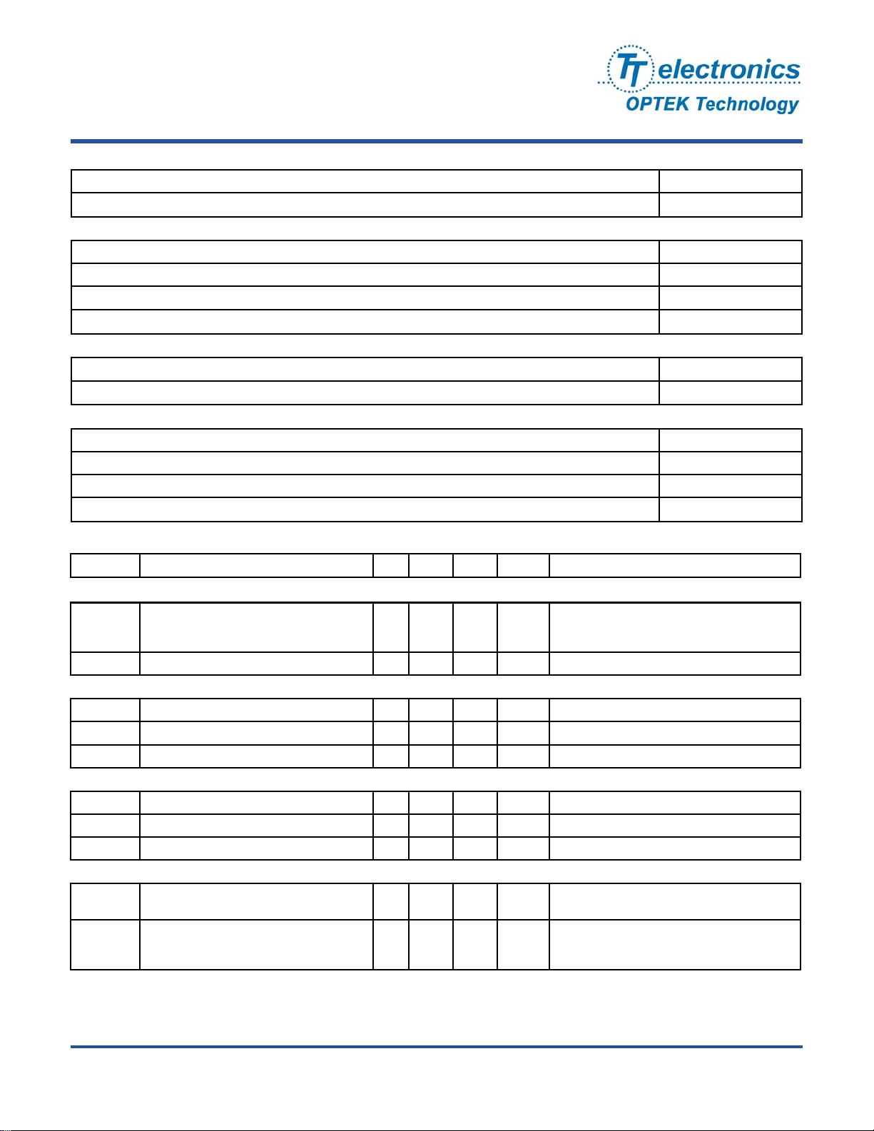
Absolute Maximum Ratings (T
=25°C unless otherwise noted)
A
Storage and Operating Temperature Range -40°C to +100° C
Lead Soldering Temperature [1/16 inch (1.6mm) from the case for 5 sec. with soldering iron]
(1)
260° C
Input Diode
Forward DC Current 50 mA
Peak Forward Current (1 μs pulse width, 300 pps) 3 A
Reverse DC Voltage 3 V
Power Dissipation
(2)
100 mW
Output Photodiode (OPB621)
Reverse Breakdown Voltage
Power Dissipation
60 V
100 mW
Output Phototransistor (OPB610, OPB620)
Collector-Emitter Voltage 24 V
Emitter-Collector Voltage 10 mA
Collector DC Current 30 mA
(3)
Power Dissipation
Electrical Characteristics (T
= 25°C unless otherwise noted)
A
200 mW
SYMBOL PARAMETER MIN TYP MAX UNITS TEST CONDITIONS
Input Diode (See OP240 for additional information)
Forward Voltage
V
OPB610, OPB620
F
OPB621
Reverse Current - - 100 µA VR = 3 V
I
R
-
1.15
-
-
1.6
1.45
V
V
IF = 10 mA
IF = 10 mA
Output Phototransistor (OPB610, OPB620) (See OP505 for additional information)
V
Collector-Emitter Breakdown Voltage 24 - - V IC = 100 µA
(BR)CEO
Emitter-Collector Breakdown Voltage 0.4 - - V ICE = 100 µA
BV
ECO
Collector-Emitter Dark Current - - 100 nA VCE = 5 V
I
CEO
Output Photodiode (OPB611, OPB621) (See OP999 for additional information)
I
Dark Current - - 65 nA VR = 30 V, EE = 0 mW
D
Reverse Breakdown Voltage 60 - - V IR = 100 µA, EE = 0 mW
V
(BR)R
Forward Voltage - - 1.0 V IF = 1 mA, EE = 0 mW
V
F
Combined
V
SAT
Collector-Emitter Saturation Voltage
OPB610, OPB620
On-State Collector/Diode Current
I
C(ON)
OPB610, OPB620
OPB611, OPB621
Notes:
(1) RMA flux is recommended. Duration can be extended to 10 seconds maximum when flow soldering. A maximum of 20 grams force may be applied to leads when solder-
ing.
(2) Derate linearly 1.33 mW/°C above 25 ° C.
(3) Derate linearly 2.0 mW/°C above 25 ° C.
(4) Plastic body is soluble in chlorinated hydrocarbons and keytones. It is recommended that a trial exposure to flux & cleaning chemicals is performed to ensure sensor is not
damaged.
-
-
1
9
-
-
0.4
-
90
V
I
= 5 mA, IC = 100 µA
F
mA
IF = 5 mA, VCE = 5 V (gap unblocked)
µA
= 5 V, IF = 20 mA (gap unblocked)
V
R
Issue C 02/2012
Page 2 of 4
Phone: (972) 323-2200 or (800) 341-4747 FAX: (972) 323-2396 [email protected] www.optekinc.com
OPTEK Technology Inc. — 1645 Wallace Drive, Carrollton, Texas 75006
Page 3
Slotted Optical Switch
OPB610, OPB611, OPB620, OPB621
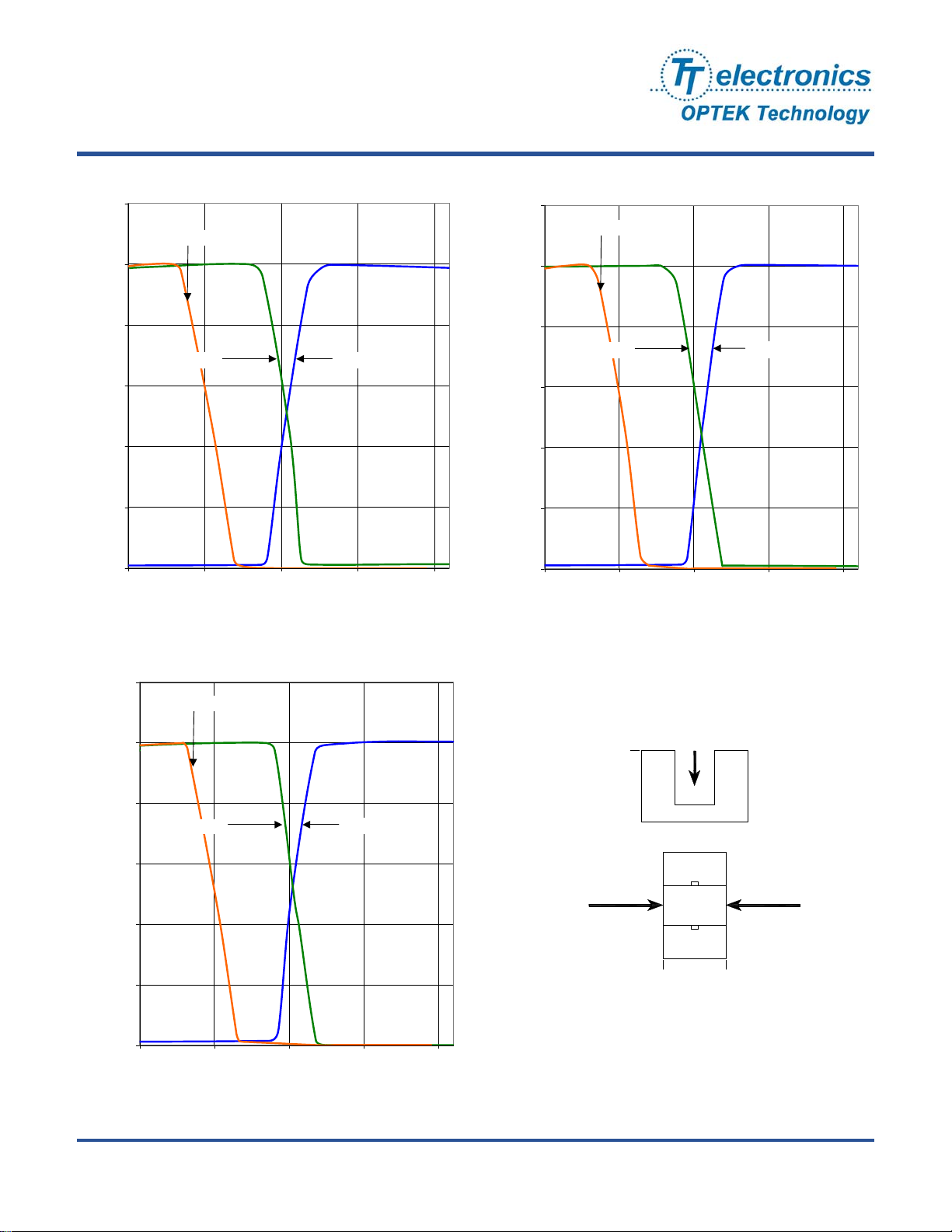
OPB610 - Flag Next to Emitter
1.20
Top to Bottom
1.00
0.80
Response
C(ON
Normalized I
0.60
0.40
0.20
0.00
Left to Right
0.00 0.05 0.10 0.15 0.20
Displacement Distance (inches)
Right to Left
OPB610 - Flag Next to Sensor
1.20
Top to Bottom
1.00
0.80
Left to Right
Response
0.60
C(ON
0.40
Normalized I
0.20
0.00
0.00 0.05 0.10 0.15 0.20
Displacement Distance (inches)
Right to Left
OPB610 - Flag in Middle of Slot
1.20
Top to Bottom
1.00
0.80
Left to Right
Response
0.60
C(ON)
0.40
Normalized I
0.20
0.00
0.00 0.05 0.10 0.15 0.20
Displacement Distance (inches)
Right to Left
Top to Bottom
0
Emitter
Left to Right Right to Left
Sensor
0 Width
OPTEK reserves the right to make changes at any time in order to improve design and to supply the best product possible.
OPTEK Technology Inc. — 1645 Wallace Drive, Carrollton, Texas 75006
Phone: (972) 323-2200 or (800) 341-4747 FAX: (972) 323-2396 [email protected] www.optekinc.com
Issue C 02/2012
Page 3 of 4
Page 4
Slotted Optical Switch
OPB610, OPB611, OPB620, OPB621
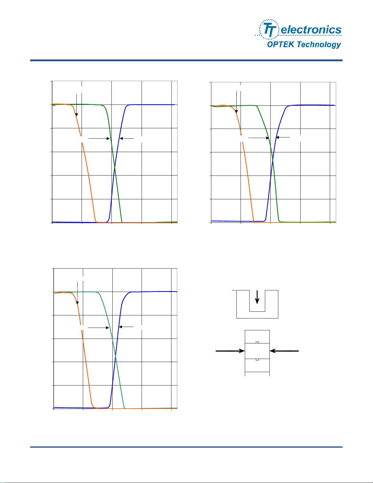
OPB620 - Flag Next to Emitter
1.20
Top to Bottom
1.00
0.80
Response
0.60
C(ON)
0.40
Normalized I
0.20
0.00
0.00 0.05 0.10 0.15 0.20
Left to Right R ight to Left
Displacement Distance (inches)
OPB620 - Flag Next to Sens or
1.20
1.00
0.80
Respone
C(ON)
0.60
0.40
Normalized I
0.20
0.00
0.00 0.05 0.10 0.15 0.20
Top to Bottom
Left to Right Right to Left
Displacement Distance (inches)
OPB620 - Flag in Middle of Slot
1.20
Top to Bottom
1.00
0.80
Response
C(ON)
0.60
0.40
Left to Right
Normalized I
0.20
0.00
0.00 0.05 0.10 0.15 0.20
Displacement Distance (inches)
Right to Left
Top to Bottom
0
Emitter
Left to Right Right to Left
Sensor
0 Width
Issue C 02/2012
Page 4 of 4
Phone: (972) 323-2200 or (800) 341-4747 FAX: (972) 323-2396 [email protected] www.optekinc.com
OPTEK Technology Inc. — 1645 Wallace Drive, Carrollton, Texas 75006
 Loading...