

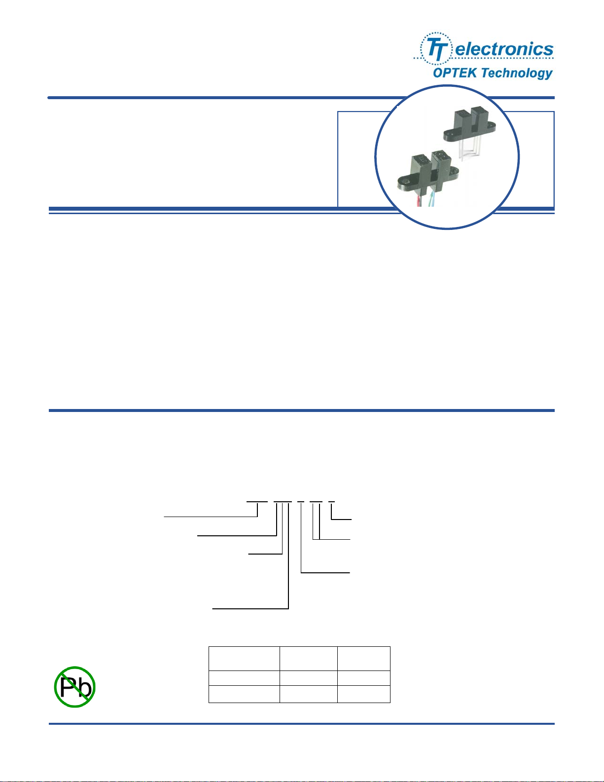
Photologic® Slotted Optical Switch
OPB960, OPB970, OPB980, OPB990 Series
Features:
• Choice of logic and output driver circuits
• Choice of aperture size, covered or open
• Wire or PCB leads
• Choice of mounting features
• Direct TTL, LSTTL, CMOS Interface
Description:
The OPB960/ 970/ 980/ 990 series of non-contact Photologic® slotted optical switches provides flexibility in meeting application
specific requirements for the design engineer.
Building from a standard housing with a 0.125” (3.18mm) wide slot, the user can specify output logic state, output driver circuit,
aperture width, aperture surface and mounting tab locations. Furthermore, an option of wire or PCB leads allows electrical
interface flexibility.
The device body is an opaque plastic which minimizes sensitivity to both visible and near-infrared external light sources which
may impact operation. Aperture width choices provide different optical resolution for motion sensing. A covered aperture
provides dust protection, while an open aperture provides maximum protection against external light sources.
Electrical operation is over a wide supply voltage range. LED emissions are near-infrared (850—940nm).
Detector digital output logic choices of buffer or inverter with totem-pole or open-collector driver circuit simplify interface for
various electrical requirements.
Custom electrical, wire and cabling services are available.
Contact your local representative or OPTEK for more information. Compliant to EU RoHS Directive 2002/95/EC .
Applications:
• Speed and direction indication
• Rotary encoders
OPTEK Assembly
Photologic
Slot Aperture Surface and Lead Options:
6 — Covered (apertures not visible), PCB leads
7 — Open (apertures visible), PCB leads
8 — Covered (apertures not visible), Wires
9 — Open (apertures visible), Wires
Logic and Output Driver Types:
0 — Buffer Totem-Pole
1 — Buffer Open-Collector
2 — Inverter Totem-Pole
3 — Inverter Open-Collector
®
Sensor Family
• Mechanical switch replacement
• Mechanical limit indication
Part Number Guide
OPB 9XX X XX X
Logic Type
Buffer OFF LOW = 0
Inverter OFF HIGH = 1
Input
LED
For more information see Application notes 201, 213
• Printers - Top of form, End of travel, Home position.
• Sliding Door Automotive and Lift gate applications
Z = Wires only, None for PCB leads
Aperture Width Guide Options:
55, 51, 11 ( See Aperture Width Guide )
Mounting Tab Location:
L — Emitter
N — None
P — Sensor
T — Both (two mounting tabs)
Output
Logic State
RoHS
OPTEK Technology Inc. — 1645 Wallace Drive, Carrollton, Texas 75006
Phone: (972) 323-2200 or (800) 341-4747 FAX: (972) 323-2396 sensors@optekinc.com www.optekinc.com
OPTEK reserves the right to make any changes at any time in order to improve design and to supply the best product possible.
Issue C.1 1/10
Page 1 of 6
Photologic® Slotted Optical Switch
OPB960, OPB970, OPB980, OPB990 Series
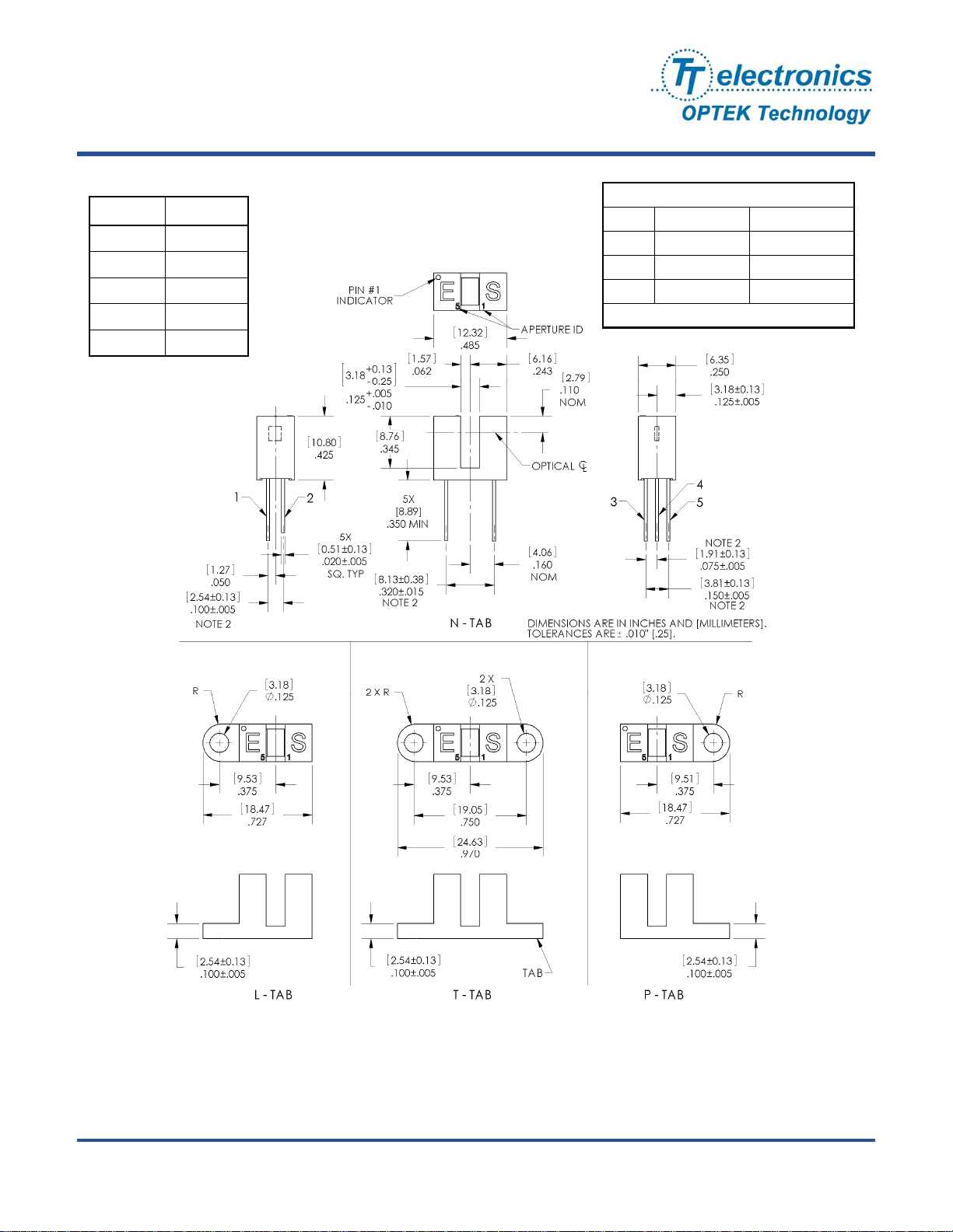
PACKAGE OUTLINE for OPB960 and OPB970 Series
TABLE 1
Lead No. Function
1 Anode
2 Cathode
3 Vcc
4 Output
5 Ground
APERTURE WIDTH GUIDE
CODE LED SENSOR
55 .050” [1.27mm] .050” [1.27mm]
51 .050” [1.27mm] .010” [0.25mm]
11 .010” [0.25mm] .010” [0.25mm]
Lengths are .050” [1.27mm]
Notes:
(1) RMA flux recommended. Duration can be extended to 10 seconds max.
(2) Feature controlled at body.
(3) Highly activated water soluble fluxes may attack plastic. Recommend trial to verify application.
(4) Maximum lead soldering temperature [1.6mm from case for 5 seconds with soldering iron] 260° C.
(5) Cathode lead may be shorter.
(6) Part number marking may be on any side.
OPTEK reserves the right to make any changes at any time in order to improve design and to supply the best product possible.
Issue C.1 1/10
Page 2 of 6
Phone: (972) 323-2200 or (800) 341-4747 FAX: (972) 323-2396 sensors@optekinc.com www.optekinc.com
OPTEK Technology Inc. — 1645 Wallace Drive, Carrollton, Texas 75006

Photologic® Slotted Optical Switch
OPB960, OPB970, OPB980, OPB990 Series
PACKAGE OUTLINE for OPB980 and OPB990 Series
TABLE 2
Wire Color Function
Red Anode
Black Cathode
White Vcc
Blue Output
Green Ground
APERTURE WIDTH GUIDE
CODE LED SENSOR
55 .050” [1.27mm] .050” [1.27mm]
51 .050” [1.27mm] .010” [0.25mm]
11 .010” [0.25mm] .010” [0.25mm]
Lengths are .050” [1.27mm]
Notes:
(7) Wire is 26AWG, UL Rated PVC insulation.
(8) Ideal torque for bolt or screw 0,45 to 0,68 Nm ( 4 to 6 Lb-in ).
(9) When using a thread lock compound, ND Industries ”ND Vibra-Tite
(10) Plastic is soluble in chlorinated hydrocarbons and ketones. Methanol or isopropanol are recommended as cleaning agents.
OPTEK reserves the right to make any changes at any time in order to improve design and to supply the best product possible.
OPTEK Technology Inc. — 1645 Wallace Drive, Carrollton, Texas 75006
Phone: (972) 323-2200 or (800) 341-4747 FAX: (972) 323-2396 sensors@optekinc.com www.optekinc.com
®
Formula 3” will avoid stress cracking plastic.
Issue C.1 1/10
Page 3 of 6

Photologic® Slotted Optical Switch
OPB960, OPB970, OPB980, OPB990 Series
Absolute Maximum Ratings
Storage Temperature Range -40°C to +85° C
Operating Temperature Range -40°C to +70° C
Input Diode (E)
Input Diode Power Dissipation 100 mW
Input Diode Forward D.C. Current, T
Input Diode Reverse D.C. Voltage, T
Sensor (S)
Supply Voltage (V
Output Photologic
to Ground) 18 V
CC
®
Power Dissipation
= 25°C 40 mA
A
= 25°C 2 V
A
200 mW
( 11)
( 14)
( 13)
( 12)
Voltage at Output Lead (Open-Collector Output), T
Short Circuit Output Current to Ground (I
Notes:
(11) Derate linearly 2.22 mW / °C above 25° C.
(12) Derate linearly 4.44 mW / °C above 25° C.
(13) Prior to 2004 Vcc was limited to 5.5V maximum.
(14) Do not connect input diode directly to a voltage source without an external current limiting resistor.
) 1 sec Max. 30 mA
OS
= 25°C 35V
A
Block Diagram
Buffer Totem-Pole
OPB960/ OPB970/ OPB980/ OPB990
Inverter Totem-Pole
OPB962/ OPB972/ OPB982/ OPB992
Buffer Open-Collector
OPB961/ OPB971/ OPB981/ OPB991
Inverter Open-Collector
OPB963/ OPB973/ OPB983/ OPB993
Issue C.1 1/10
Page 4 of 6
OPTEK reserves the right to make any changes at any time in order to improve design and to supply the best product possible.
OPTEK Technology Inc. — 1645 Wallace Drive, Carrollton, Texas 75006
Phone: (972) 323-2200 or (800) 341-4747 FAX: (972) 323-2396 sensors@optekinc.com www.optekinc.com

Photologic® Slotted Optical Switch
OPB960, OPB970, OPB980, OPB990 Series
Electrical Characteristics (T
= -40° C to +70° C unless otherwise noted)
A
SYMBOL PARAMETER MIN TYP MAX UNITS TEST CONDITIONS
Input Diode (See OP140 / OP240 LED for additional information)
Forward Voltage - - 1.70 V IF = 20 mA, TA = 25° C
V
F
I
Reverse Current - - 100 µA VR = 2.0 V, TA = 25° C
R
Coupled (See OPL560 Detector for additional information)
Operating D.C. Supply Voltage 4.5 - 16 V
V
CC
I
Supply Current - - 12 mA VCC = 4.5V to 16V
CC
V
Low Level Output Voltage:
OL
Buffer Totem-Pole OPB960,OPB970
OPB980,OPB990
Buffer Open-Collector OPB961,OPB971
OPB981,OPB991
Inverter Totem-Pole OPB962,OPB972
OPB982,OPB992
Inverter Open-Collector OPB963,OPB973
OPB983,OPB993
V
High Level Output Voltage:
OH
Buffer Totem-Pole OPB960,OPB970
OPB980,OPB990
Inverter Totem-Pole OPB962,OPB972
OPB982,OPB992
- - 0.4 V
V
-2.1 - - V
CC
= 4.5V, IOL = 12.8mA
V
CC
I
= 0 mA
F
(14)
VCC = 4.5V, IOL = 12.8mA
I
= 15 mA
F
VCC = 4.5V to 16V, IOH = -800µA
= 15 mA
I
F
VCC = 4.5V to 16V, IOH = -800µA
= 0 mA
I
F
(14)
I
High Level Output Current:
OH
Buffer Open-Collector OPB961,OPB971
OPB981,OPB991
Inverter Open-Collector OPB963,OPB973
- - 100 µA
OPB981,OPB991
I
(+) LED Positive-Going Threshold Current
F
I
(+) / IF(-) Hysteresis Ratio - 1.5 - - VCC = 5.0V
F
t
, tF Output Rise Time, Output Fall Time - 70 - ns
R
(16)
- - 15 mA VCC = 5.0V, TA = 25° C
V
= 4.5V to 16V, VOH = 30V
CC
= 15 mA
I
F
VCC = 4.5V to 16V, VOH = 30V
I
= 0 mA
F
= 5.0V, I
V
CC
100 kHz square wave, C = 10pF max.
= 360 Ω to GND (Totem-Pole)
R
Propagation Delay Time
, t
t
PLH
Notes:
14) Normal application would be with light source blocked, simulated by I
15) All parameters are tested using pulse techniques.
16) An increasing current applied to the LED which causes the output logic state to change.
OPTEK Technology Inc. — 1645 Wallace Drive, Carrollton, Texas 75006
Phone: (972) 323-2200 or (800) 341-4747 FAX: (972) 323-2396 sensors@optekinc.com www.optekinc.com
PHL
Low to High, High to Low
For proper application IF(+), LED current, should be more than the stated maximum.
OPTEK reserves the right to make any changes at any time in order to improve design and to supply the best product possible.
- 5.0 - µs
= 0 mA.
F
L
= 1KΩ pull-up (Open-Collector)
R
L
(14)
= 15 mA, TA = 25° C
F peak
Issue C.1 1/10
Page 5 of 6

Photologic® Slotted Optical Switch
OPB960, OPB970, OPB980, OPB990 Series
Logic Output vs Left to Right Bocking Distance (X-Axis Blocked)
5.0
4.0
3.0
VCC = 5 Volts
IF = 20mA
Buffer Totem-Pole
Aperture Width 11
Aperture Width 51
2.0
Logic Output (V)
1.0
0.0
0.000 0.025 0.050 0.075 0.100 0.125 0.150 0.175 0.200 0.225 0.250
Aperture Width 55
Distance (inc hes)
Logic Output vs Top to Bottom Bocking Distance (Y-Axis Blocked)
5.0
VCC = 5 Volts
IF = 20mA
4.0
3.0
2.0
Logic Output (V)
1.0
0.0
0.000 0.025 0.050 0.075 0.100 0.125 0.150 0.175 0.200 0.225 0.250
Distance (inches)
OPTEK reserves the right to make any changes at any time in order to improve design and to supply the best product possible.
Buffer Totem-Pole
Issue C.1 1/10
Page 6 of 6
Phone: (972) 323-2200 or (800) 341-4747 FAX: (972) 323-2396 sensors@optekinc.com www.optekinc.com
OPTEK Technology Inc. — 1645 Wallace Drive, Carrollton, Texas 75006
 Loading...