

OPTEK OPB821TXV, OPB821TX Datasheet
Fea tures
• Non-contact switching
• Hermetically sealed components
• Components processed to Optek’s
screening program patterned after
MIL-PRF-19500 for TX and TXV
devices
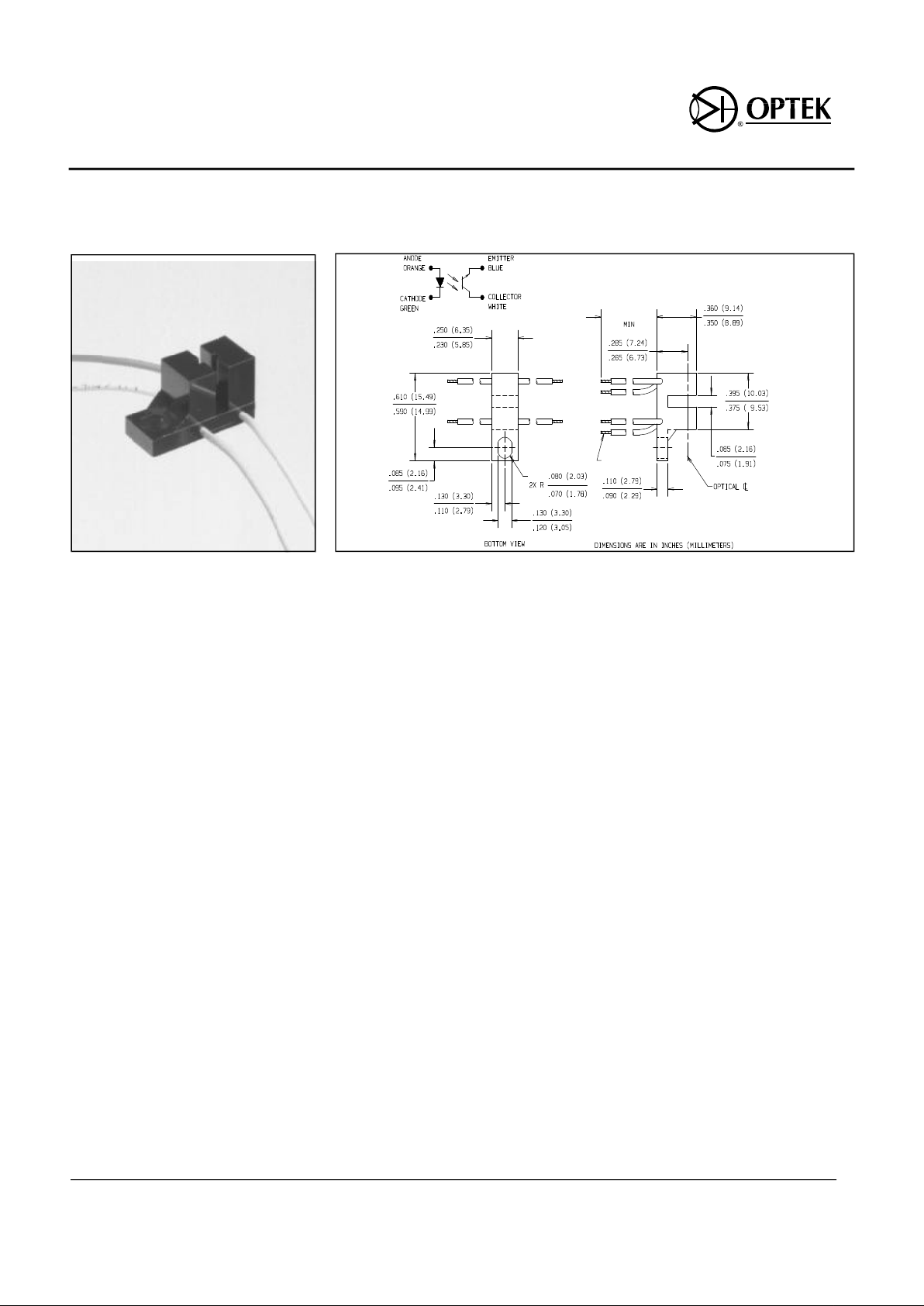
De scrip tion
The OPB821TX or OPB821TXV consists
of a gallium aluminum arsenide LED and
a silicon phototransistor soldered into a
printed circuit board, then mounted in a
high temperature plastic housing on
opposite sides of an 0.080 inch (2.03
mm) wide slot. Lead wires are #24 AWG
polytetraflouroethylene (PTFE) insulated
conforming to MIL-W-16878.
Phototransistor switching takes place
whenever an opaque object passes
through the slot. For maximum output
signal, neither the LED or the
phototransistor in the OPB821TX or the
OPB821TXV is apertured.
The OPB821TX and OPB821TXV use
optoelectronic components that have
been processed and tested as either TX
or TXV components per MIL-PRF-19500.
Typical screening and lot acceptance
tests are provided on page 13-4.
Ab so lute Maxi mum Rat ings (TA = 25o C un less oth er wise noted)
Op er at ing Tem pera ture Range . . . . . . . . . . . . . . . . . . . . . . . . . . . . -65o C to +125o C
Stor age Tem pera ture Range . . . . . . . . . . . . . . . . . . . . . . . . . . . . . . -65o C to +150o C
In put Di ode
For ward DC Cur rent. . . . . . . . . . . . . . . . . . . . . . . . . . . . . . . . . . . . . . . . . . . . . . 50 mA
Re verse Volt age. . . . . . . . . . . . . . . . . . . . . . . . . . . . . . . . . . . . . . . . . . . . . . . . . . 2.0 V
Power Dis si pa tion . . . . . . . . . . . . . . . . . . . . . . . . . . . . . . . . . . . . . . . . . . . . 100 mW
(1)
Out put Pho to tran sis tor
Collector- Emitter Volt age. . . . . . . . . . . . . . . . . . . . . . . . . . . . . . . . . . . . . . . . . . . . 50 V
Emitter- Collector Volt age . . . . . . . . . . . . . . . . . . . . . . . . . . . . . . . . . . . . . . . . . . . 7.0 V
Power Dis si pa tion . . . . . . . . . . . . . . . . . . . . . . . . . . . . . . . . . . . . . . . . . . . . 100 mW
(1)
Notes:
(1) Derate Linearly 1.00 mW/o C above 25o C.
(2) Methanol or isopropanol are recommended cleaning agents.
Prod uct Bul le tin OPB821TX
Sep tem ber 1996
Hi- Rel Slot ted Op ti cal Switches
Types OPB821TX, OPB821TXV
Op tek Tech nol ogy, Inc. 1215 W. Crosby Road Car roll ton, Texas 75006 (972) 323- 2200 Fax (972) 323- 2396
24.0 (609.60)
13-38
#24 AWG
Types OPB821TX, OPB821TXV
Op tek re serves the right to make changes at any time in or der to im prove de sign and to sup ply the best prod uct pos si ble.
Op tek Tech nol ogy, Inc. 1215 W. Crosby Road Car roll ton, Texas 75006 (972)323- 2200 Fax (972)323- 2396
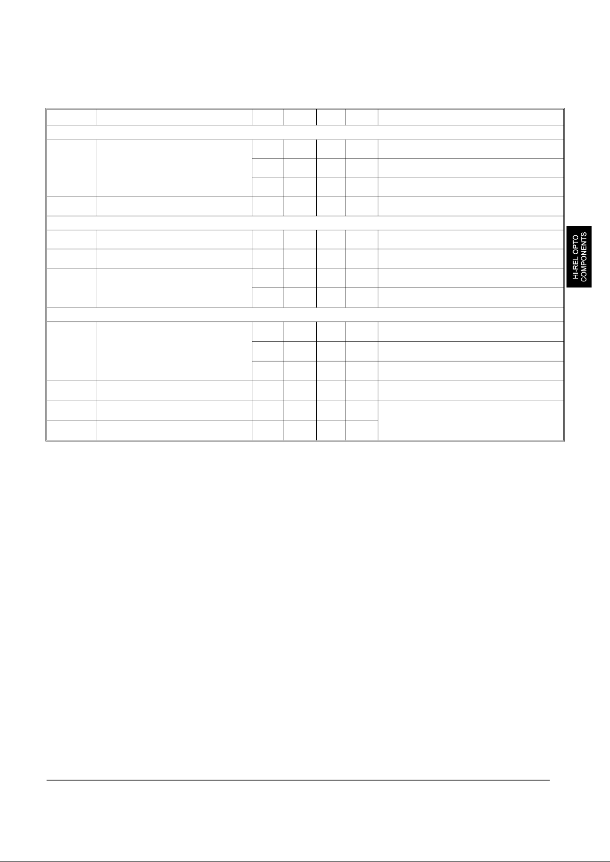
Elec tri cal Char ac ter is tics (TA = 25o C un less oth er wise noted)
Sym bol Pa rame ter Min Typ Max Units Test Con di tions
In put Di ode
V
F
Forward Voltage
(3)
1.00 1.35 1.70 V IF = 20.0 mA
1.20 1.55 1.90 V IF = 20.0 mA, TA = -55o C
0.80 1.20 1.60 V IF = 20.0 mA, TA = 100o C
I
R
Reverse Current
0.1 100
µA
VR = 2.0 V
Out put Pho to tran sis tor
V
(BR)CEO
Collector-Emitter Breakdown Voltage 50 110 V IC = 1.0 mA, IF = 0
V
(BR)ECO
Emitter-Collector Breakdown Voltage
7.0 10.0 V
IE = 100 µA, IF = 0
I
C(off)
Collector-Emitter Dark Current 0.2 100 nA VCE = 10.0 V, IF = 0
10 100
µA
VCE = 10.0 V, IF = 0, TA = 100o C
Cou pled
I
C(on)
On-State Collector Current
(3)
800
µA
VCE = 10.0 V, IF = 20.0 mA
500
µA
VCE = 10.0 V, IF = 20.0 mA, TA = -55o C
500
µA
VCE = 10.0 V, IF = 20.0 mA, TA = 100o C
V
CE(SAT)
Collector-Emitter Saturation Voltage
0.20 0.30 V
IC = 250 µA, IF = 20.0 mA
t
r
Output Rise Time
12.0 20.0
µs
VCC = 10.0 V, IF = 20.0 mA,
RL = 1,000 Ω
t
f
Output Fall Time
12.0 20.0
µs
(3) Meas ure ment is taken dur ing the last 500 µs of a sin gle 1.0 ms test pulse. Heat ing due to in creased pulse rate or pulse width can cause
change in meas ure ment re sults.
13-39
 Loading...