

Page 1
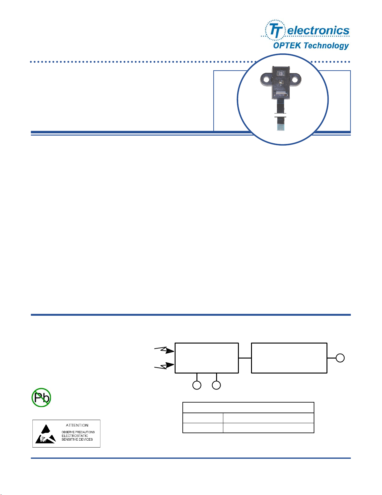
Reflective Color Sensor Assembly
OPB780Z
Features:
• High-resolution conversion of light intensity to frequency
• Selectable color output frequency
• Communicates directly with a microcontroller
• Sensor power supply operation (2.7 V to 5.5 V)
• LED power separate input
• Includes LED, Sensor and interface cable
Description:
The OPB780Z color sensor uses a light-to-frequency converter that combines 64 configurable silicon photodiodes
(on a 144 um center and measuring 120 um x 120 um each), with a white LED in a small, lightweight package that
makes it ideal for using in miniature applications.
The output is a square wave (50% duty cycle) with a frequency directly proportional to reflected light intensity
(irradiance).
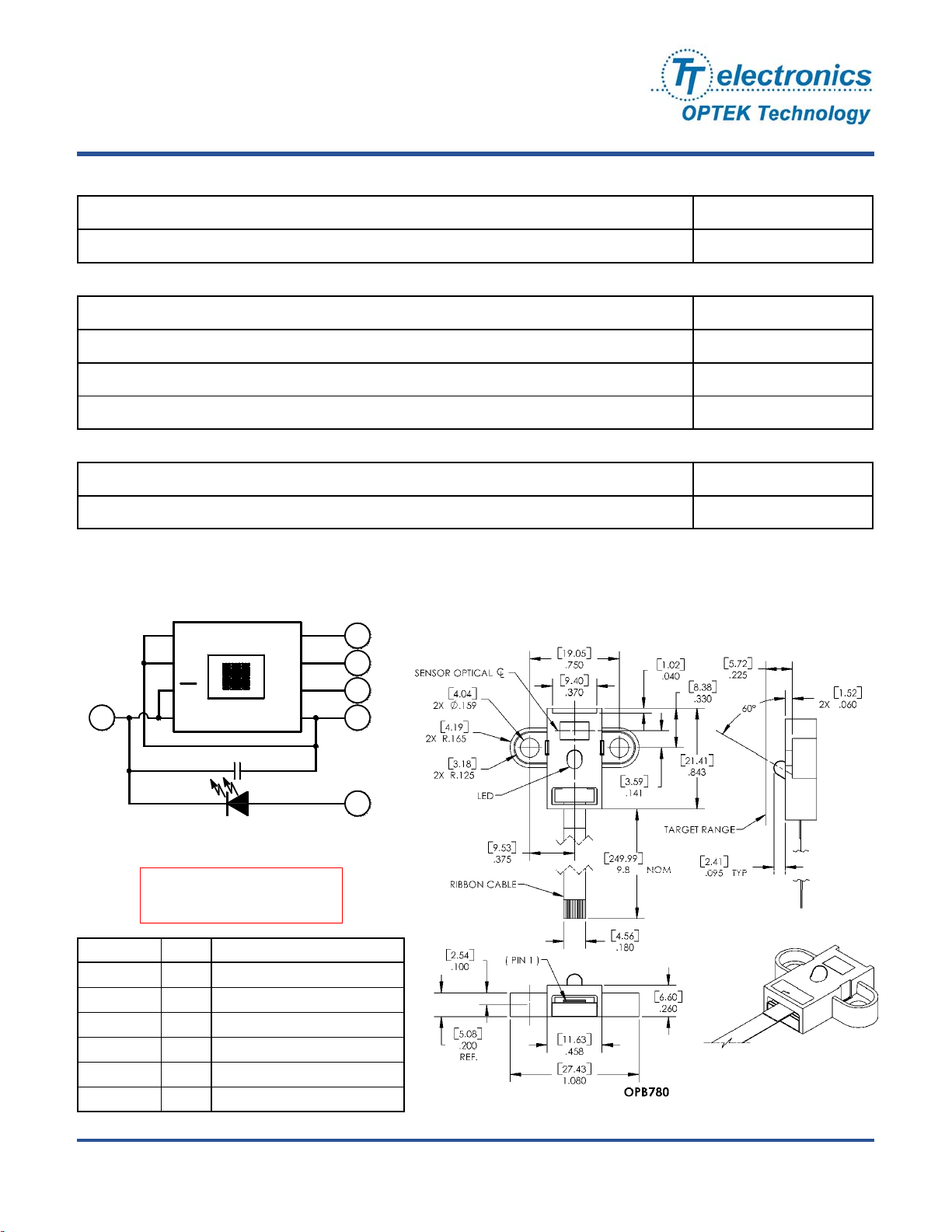
The light-to-frequency converter reads an 8 x 8 array of photodiodes that consists of four groups of 16 photodiodes
each, segregated by color: 16 photodiodes with red filters, 16 photodiodes with green filters, 16 photodiodes with
blue filters and 16 clear photodiodes with no filters. Each color’s group of 16 photodiodes is interdigitated to
minimize the effect of non-uniformity of the incident irradiance. Each color’s group is also connected in parallel.
The type of photodiode used during operation is pin-selectable.
The output of the device is designed to drive a standard TTL or CMOS logic input over short distances.
The internal photodiode used by the device is controlled by two logic inputs, S2 and S3. See page 4 for more
information.
A 10 “ [25.4 cm] Flat Flexible Cable (FFC) is included for easy hook-up.
The FFC is designed to interface with an AVX (ELCO) part number 04 6249 0080 00 800 connector.
For more information, contact your local representative or OPTEK.
Applications:
Block Diagram
• Photographic equipment
• Colormetry
• Chemical analyzers
• Display contrast controls
Light
• High resolution digital measurement of light
intensity
RoHS
OPTEK reserves the right to make changes at any time in order to improve design and to supply the best product possible.
OPTEK Technology Inc. — 1645 Wallace Drive, Carrollton, Texas 75006
Phone: (972) 323-2200 or (800) 341-4747 FAX: (972) 323-2396 sensors@optekinc.com www.optekinc.com
Photodiode Array
S3S2
6
OPB780Z OPB780 with 10” Long Flat Flex Cable
KA3128 10” Long Flat Flex Cable
4
Ordering Information
Current-to-Frequency
Converter
Out
Issue A.3 04/07
3
Page 1 of 6
Page 2
Reflective Color Sensor Assembly
OPB780Z
Absolute Maximum Ratings
Operating Temperature
Storage Temperature
LED—Absolute Maximum Ratings
Reverse Voltage V
1, 2
(T
= 25° C unless otherwise noted)
A
1, 2
(T
= 25° C unless otherwise noted)
A
T
= -30° C to +85° C
OPR
= -30° C to +85° C
T
STG
= 5 V
R
Forward Current IF = 30 mA
Power Dissipation P
Peak Forward Current I
= 120 mW
D
= 100 mA
FP
Sensor—Absolute Maximum Ratings1, 2 (over operating free-air temperature range unless otherwise noted)
Supply Voltage(V
Input Voltage (all inputs, V
Notes:
Stresses beyond those linked under “absolute maximum rating” may cause permanent damage to device. These are only stress
(1)
ratings, and functional operating of the device at these (or any other) conditions beyond those indicated in the Recommended Operating
Conditions table shown above may affect the device’s reliability.
(2) All voltage values are with respect to GND.
) 6 V
DD
) -0.3 V to VDD + 0.3 V
I
7,8
SO
S1
OE
Gnd
Cap (0.1µf)
LED
DO NOT LOOK DIRECTLY AT LED
WITH UNSHIELDED EYES OR
DAMAGE TO RETINA MAY OCCUR.
Out
V
S3
S2
DD
6
4
3
1,2
5
Pin Name Pin # Description
VDD 1, 2 Supply voltage
OUT 3 Output Frequency (F
S2 4 Photodiode type selection input
LED Anode 5 LED input
S3 6 Photodiode type selection input
GND 7, 8 Power supply ground
)
O
Issue A.3 04/07
Page 2 of 6
OPTEK reserves the right to make changes at any time in order to improve design and to supply the best product possible.
OPTEK Technology Inc. — 1645 Wallace Drive, Carrollton, Texas 75006
Phone: (972) 323-2200 or (800) 341-4747 FAX: (972) 323-2396 sensors@optekinc.com www.optekinc.com
Page 3

Reflective Color Sensor Assembly
OPB780Z
LED
Electro-Optical Characteristics of LED
SYMBOL MIN TYP MAX UNITS TEST CONDITIONS
(1)
Luminous Intensity - 1.0 - cd IF = 20 mA
I
V
Forward Voltage 2.8 3.4 3.9 V IF = 5 mA
V
F
Reverse Current - - 10 µA VR = 5 V
I
R
PARAMETER
Sensor
Recommended Operating Conditions
1
(T
= 25°C unless otherwise noted) (See OVLAW4CB6 for more info.)
A
1
SYMBOL PARAMETER MIN TYP MAX UNITS RECOMMENDED CONDITIONS
V
Supply Voltage 2.7 5 5.5 V -
DD
V
High-Level Input Voltage 2.0 - VDD V VDD = 2.7 V to 5.5 V
IH
Low-Level Input Voltage 0.0 - 0.8 V VDD = 2.7 V to 5.5 V
V
IL
Operating Free-Air Temperature
T
A
Range
Sensor
Electrical Characteristics
1
(T
= 25° C, V
A
-40 - +70 °C -
= 5 V unless otherwise noted)
DD
SYMBOL PARAMETER MIN TYP MAX UNITS TEST CONDITIONS
VOH High-Level Output Voltage 3 - 4.5 - V IOH = -4 mA
Low-Level Output Voltage 3 - 0.25 - V IOL = 4 mA
V
OL
High-Level Input Current - - 5 µ -
I
IH
Low-Level Input Current - - 5 µ -
I
IL
I
t
r
Supply Current
- 2 3 mA Power on
DD
2
- Full-Scale Frequency
Temperature Coefficient of
Output Frequency
Typical Temperature Rise Time
, tf
Typical Temperature Fall Time
- 600 - kHz -
- ±200 - ppm/°C
λ ≤ 700 nm, -25° C ≤ T
ppm/° C
≤ 70° C / ± 200
A
- 100 - µ sec. -
Notes:
(1) All voltage values are with respect to GND.
(2) Full-scale frequency is the maximum operating frequency of the device without saturation.
(3) Output interface of device is designed to drive a standard TTL or CMOS logic input over short distances. If lines greater than 12 inches are
used on output, a buffer or line driver is recommended.
OPTEK reserves the right to make changes at any time in order to improve design and to supply the best product possible.
OPTEK Technology Inc. — 1645 Wallace Drive, Carrollton, Texas 75006
Phone: (972) 323-2200 or (800) 341-4747 FAX: (972) 323-2396 sensors@optekinc.com www.optekinc.com
Issue A.3 04/07
Page 3 of 6
Page 4
Reflective Color Sensor Assembly
OPB780Z
Coupled Characteristics
1
(VDD = 5 V, T
RED
SYMBOL PARAMETER
S2=L/S3=L
16.0 K 3.5 K 2.7 K 23.9 K
kHz
Output Frequency
See note
(9)
4.0 K 7.5 K 5.2 K 19.9 K
2.2 K 3.4 K 9.5 K 16.1 K
35.7 K 35.8 K 39.3 K 126.0 K
Notes:
(1) All voltage values are with respect to GND.
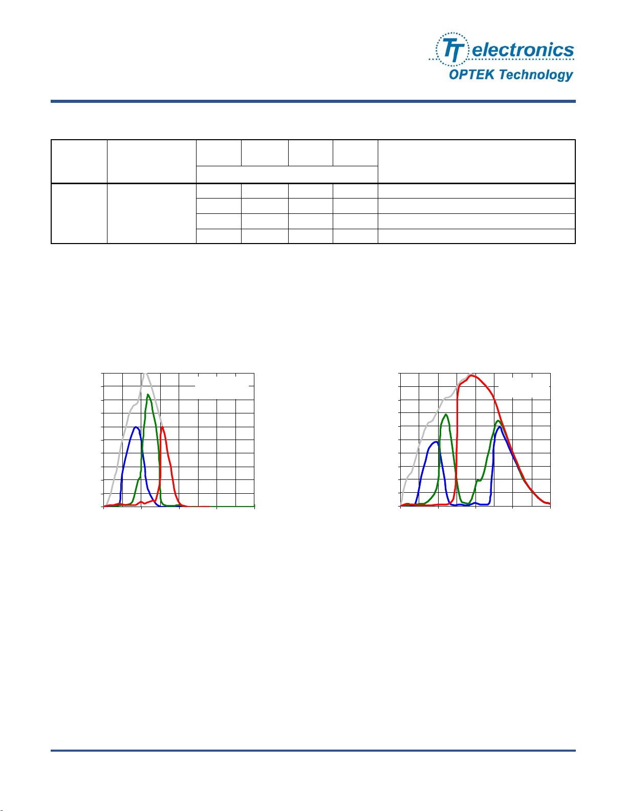
Typical Electro-Optical Characteristics Curves
Spectral Response
with Hoya CM230 Filter (not included)
1.0
0.9
0.8
0.7
0.6
0.5
0.4
0.3
0.2
Relative R esponsivity
0.1
0.0
300 500 700 900 1100
λp Wavelength (nm)
No rmalized to
Clear @ 530 nm
TA = 25° C
= 25 °C, IF = 5mA)
A
GREEN
S2=H/S3=H
BLUE
S2=L/S3=H
TYPICAL
OPB780Z Sensor -
CLEAR
S2=H/S3=L
Relative Responsivity
PARAMETER
IF = 5 mA, D = 0.225 inch, with red target
IF = 5 mA, D = 0.225 inch, with green target
I
= 5 mA, D = 0.225 inch, with blue target
F
I
= 5 mA, D = 0.225 inch, with white target
F
Spectral Response
Photodiode Spectral Responsivity
1.0
0.9
0.8
0.7
0.6
0.5
0.4
0.3
0.2
0.1
0.0
300 500 700 900 1100
No rmalized to
Clear @ 680 nm
TA = 25° C
λp Wavelength (nm)
Issue A.3 04/07
Page 4 of 6
OPTEK reserves the right to make changes at any time in order to improve design and to supply the best product possible.
OPTEK Technology Inc. — 1645 Wallace Drive, Carrollton, Texas 75006
Phone: (972) 323-2200 or (800) 341-4747 FAX: (972) 323-2396 sensors@optekinc.com www.optekinc.com
Page 5
Reflective Color Sensor Assembly
C
OPB780Z
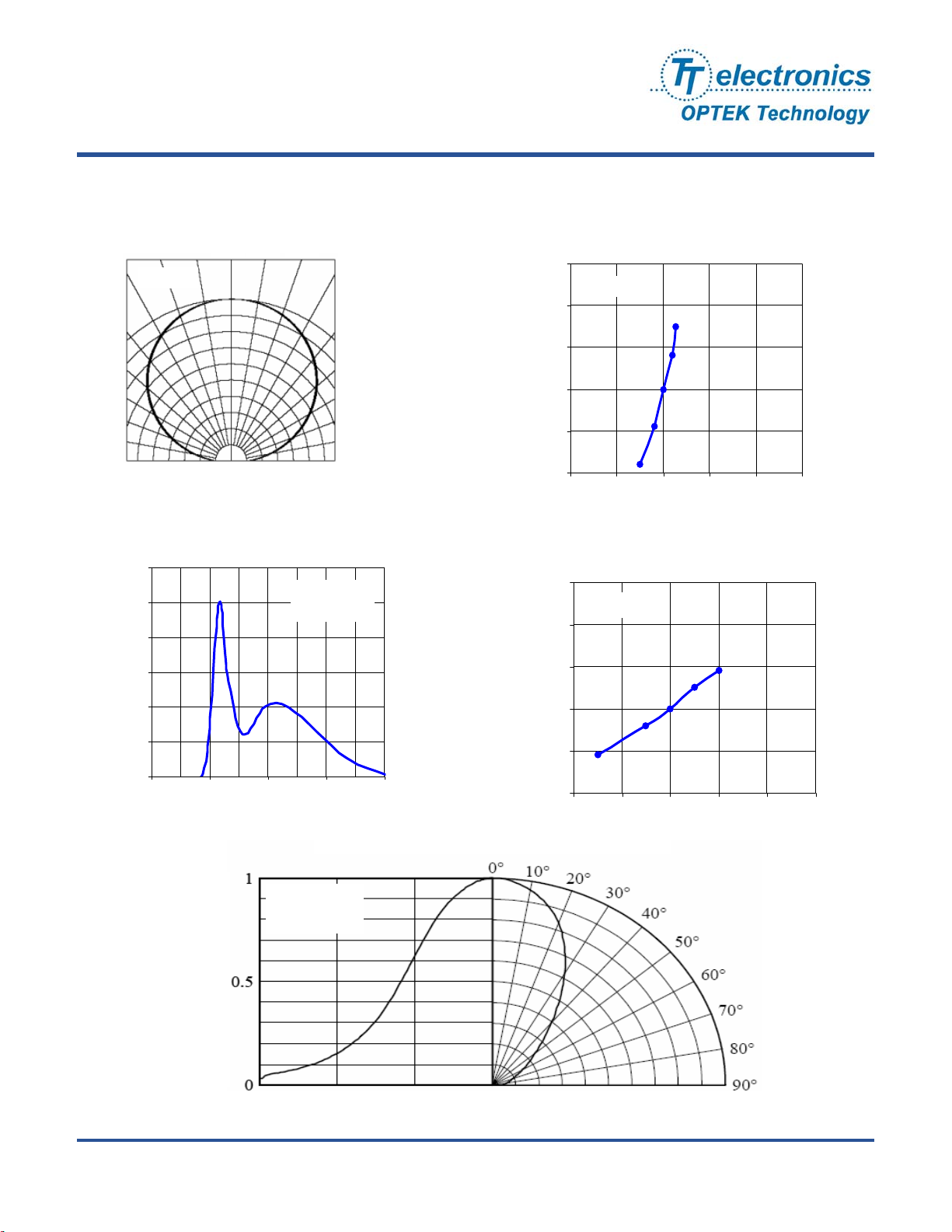
OPB780Z Sensor & LED - Typical Electro-Optical Characteristics Curves
Sensor Radiation Diagram
0° 10° 20°
TA = 25°
1.0
0.9
0.8
0.7
0.5 0.3 0.1 0.2 0.4
Spectrum
LED Spectrum
1.2
1.0
0.8
0.6
(a.u.)
0.4
0.2
Relative Emission Intensity
0.0
350 450 550 650 750
Wavele ngth λ p (nm )
30°
40°
50°
60°
70°
80°
90°
0.6
TA = 25° C
= 20 mA
I
F
0.35
0.34
0.33
Y
0.32
0.31
0.30
Y
LED Directivity
Forwa rd Curre nt vs Chrom a ti ci ty
Coordinate
TA = 25° C
1 mA
5 mA
20 mA
50 mA
100 mA
0.29 0.30 0.31 0.32 0.33 0.34
X
Ambient Temperature vs Chromaticity
Coordinate
0.35
IFP = 20 mA
0.34
0.33
0.32
50° C
0.31
85° C
0.30
0.29 0.30 0.31 0.32 0.33 0.34
-30° C
0°
25° C
X
TA = 25° C
I
= 20 mA
F
Relative Luminosity (a.u.)
Radiation Angle
OPTEK reserves the right to make changes at any time in order to improve design and to supply the best product possible.
OPTEK Technology Inc. — 1645 Wallace Drive, Carrollton, Texas 75006
Phone: (972) 323-2200 or (800) 341-4747 FAX: (972) 323-2396 sensors@optekinc.com www.optekinc.com
Issue A.3 04/07
Page 5 of 6
Page 6
Reflective Color Sensor Assembly
A
)
)
)
A
OPB780Z
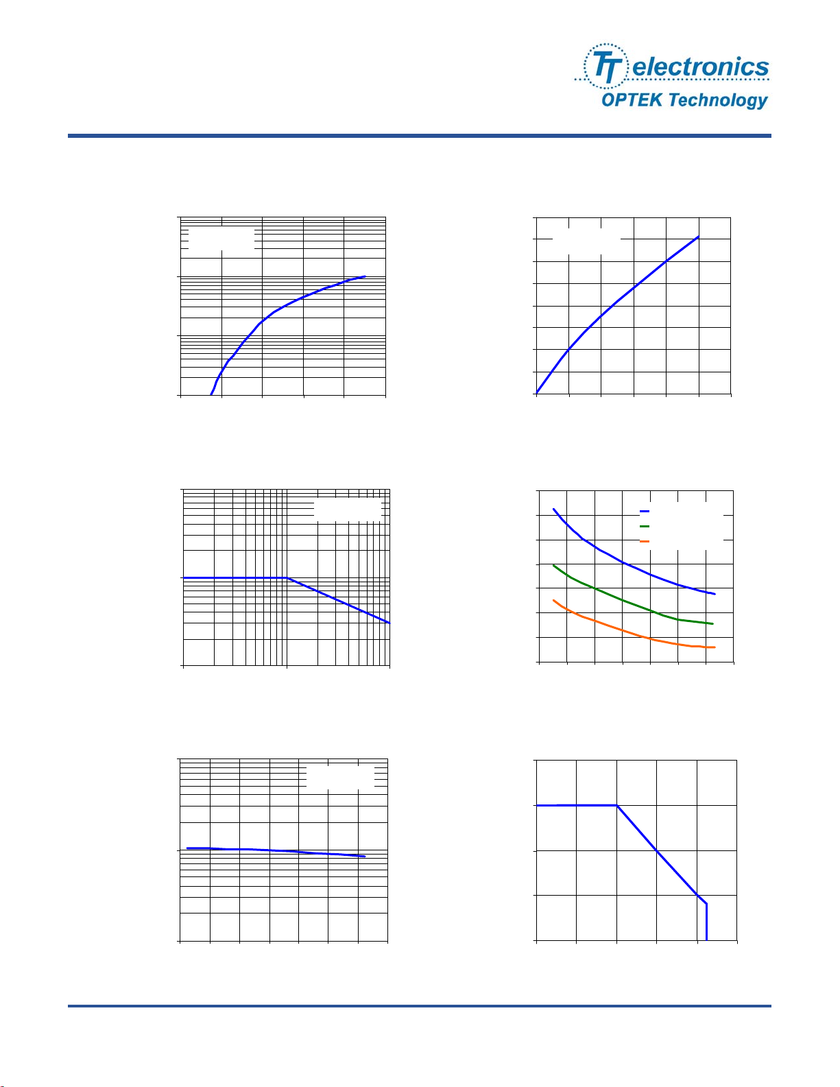
OPB780Z LED - Typical Electro-Optical Characteristics Curves
Forward Voltage vs Forward
Current
1000
TA = 25o C
(mA)
FP
100
10
Forward C urrent I
1
2.5 3.0 3.5 4.0 4.5 5.0
Forward Voltage VF (V)
Duty Ratio vs Allowable
Forward Current
1000
100
(mA)
FP
I
TA = 25o C
Forward Current vs Relative
Luminousity
4.0
Re la tive Lum inous ity (a.u.
(V)
F
3.5
3.0
2.5
2.0
1.5
1.0
0.5
0.0
5.4
5.0
4.6
4.2
3.8
3.4
TA = 25o C
0 20 40 60 80 100 120
Forward Current IFP (mA)
mbient Temperature vs Forw ard
Voltage
IFP = 60 mA
= 20 mA
I
FP
= 5 mA
I
FP
3.0
Forward Voltage V
Allowable Forwa rd Curre nt
10
1 10 100
Duty Ratio (%)
Ambient Temperature vs Relative
Luminosity
10.0
IFP = 20 mA
2.6
-40 -20 0 20 40 60 80 100
Ambient Tempera ture TA (oC)
mbient Temperature vs Allowable
For w a r d Cur r e nt
40
30
1.0
20
(mA)
F
I
10
Issue A.3 04/07
Page 6 of 6
Relative Luminosity (a.u.
0.1
-40 -20 0 20 40 60 80 100
Ambient Temperature T(°C
OPTEK reserves the right to make changes at any time in order to improve design and to supply the best product possible.
Phone: (972) 323-2200 or (800) 341-4747 FAX: (972) 323-2396 sensors@optekinc.com www.optekinc.com
Allowable Forward Current
0
0 20406080100
Ambient Temperature T
OPTEK Technology Inc. — 1645 Wallace Drive, Carrollton, Texas 75006
(oC)
A
 Loading...