

Page 1
Long Distance Reflective Switch
OPB720A and OPB720B Series
Features:
• 0.04” to 12” (1 mm to 305 mm) with 90% reflective material.
(Typical Maximum detection distance to be set at factory)
• Recognizes objects as small as 0.08” (2 mm)
• Ambient light rejection < 100K Lux
• Open collector output
• Cable length 39” (990 mm) lead length 28 AWG wire
Description:
The OPB720A and OPB720B Series reflective switches detects o bjects as far away as 12” (305 mm) using
standard 90% reflective material, and can detect objects as small as 0.08” (2 mm). The OPB720 series consist of
three standard reflective switching distances -06Z for typically 6” (152 mm), -12Z for typically 12” (305 mm) and
-30VZ for typically 30” (762 mm). The power supply voltage range of the OPB720A series is 10 to 30 volts while
the power supply voltage range for the OPB720B is 4 to 7 volts.
The OPA720A and OPB720B sensors are NOT affected by ambient light in most conditions. Ambient light
conditions are compensated by using a synchronous driver detection scheme.
This sensor has a logical output that switches from a high level with reflective target to a low level with no reflective
target. With the addition of hysteresis, the OPB720 series minimizes output switching oscillations. The type of
material used for the target is very dependent on the distance that can be achieved for the sensor. Taking this into
consideration, the OPB720 series can be used in either a reflective or interruptive mode. As an example, the
OPB720A-12Z can easily be used in a reflective mode for distances around 12” (305 mm) while when reflecting off
a retro-reflective target similar to 3M 3870 or Nippon Crystallite at distances around 85” (216 mm) the device
works well in the interruptive mode. See the included charts for typical distances with different reflective material
for other versions of the OPB720 series devices.
The OPB720 series has an open collector output transistor and power req uirements are compatible with most
PLCs and TTL gates.
Product Photo Here
Applications:
• Conveyer belt package recognition
• Personnel movement recognition
• Near-focus security systems
• Hand wash and soap dispensing stations
• Toilet and urinal sensors
• Product dispensing systems
Vcc
Electronics
Part Number Description
OPB720A-06Z
OPB720B-06Z
OPB720A-12Z
OPB720B-12Z
OPB720A-30VZ
OPB720B-30VZ
Output
Ordering Information
Maximum detection of 0.04” to 6” (1.0 mm to 152 mm)
39” (991 mm) lead length with 28 AWG wire, using white 90%
Maximum detection of 0.04” to 12” (1.0 mm to 305 mm)
39” (991 mm) lead length with 28 AWG wire, using white 90%
Maximum detection of 0.04” to 30” (1.0 mm to 762 mm)
39” (991 mm) lead length with 28 AWG wire, using white 90%
Ground
RoHS
OPTEK Technology Inc. — 1645 Wallace Drive, Carrollton, Texas 75006
Phone: (972) 323-2200 or (800) 341-4747 FAX: (972) 323-2396 sensors@optekinc.com www.optekinc.com
OPTEK reserves the right to make changes at any time in order to improve design and to supply the best product possible.
reflective paper
reflective paper
reflective paper
Additional laser safety information can be found
on the Optek website. See application #221.
Classification is not marked on the device due to
space limitations. See package outline for
centerline of optical radiance. Operating de-
vices beyond maximum rating may cause de-
vices to exceed rated classification
Issue F 07/07
Page 1 of 5
Page 2

Long Distance Reflective Switch
OPB720A and OPB720B Series
Pin # Description
Red VCC
White Output
Black Ground
DIMENSIONS ARE IN:
[ MILLIMETERS]
INCHES
Absolute Maximum Ratings (T
=25°C unless otherwise noted)
A
Operating Temperature Range
OPB720A Series
OPB720B Series
0° C to + 50° C
0° C to + 70° C
Storage Temperature Range -40° C to + 80° C
Lead Soldering Temperature (1/16” (1.6 mm) from case for 5 seconds with soldering iron) 260° C
Supply Voltage (VCC)
OPB720A Series
OPB720B Series
10 to 30 Volts
4 to 7 Volts
Maximum Collector Voltage 30 V
Collector DC Current (Sink) 50 mA
Power Dissipation 300 mW
Electrical Characteristics (T
= 25°C unless otherwise noted)
A
SYMBOL PARAMETER MIN TYP MAX UNITS TEST CONDITIONS
Low Level Output Voltage
V
OL
OPB720A Series
OPB720B Series
High Level Output Voltage
VOH
OPB720A Series
OPB720B Series
Notes:
(1) RMA flux is recommended. Duration can be extended to 10 seconds maximum when flow soldering.
(2) Distance for OPB720A-06Z=6 “ (152 mm), Distance for OPB720A-12Z=12” (305mm), Distance for OPB720A-30VZ=30” (762 mm)
-
-
5.0
3.5
-
0.8
-
0.8
-
-
-
-
V
V
VCC = 10 Volts, Note 4
= 4 Volts, Note 4
V
CC
VCC = 10 Volts, Note 5
= 4 Volts, Note 5
V
CC
(3) OPB720A-30VZ & OPB720B-30VZ are class 1M laser safety device. Do Not look at the device closer than 4” (100 mm) with a
magnifying device.
(4) R
= 10 K, VCE = VCC Distance = See Note 2 & 3, (No Target)
L
(5) R
= 10 K, VCE = V
L
(90% Reflective Surface, Kodak—EK E152-7798)
CC,
OPTEK reserves the right to make changes at any time in order to improve design and to supply the best product possible.
(1)
Issue F 07/07
Page 2 of 5
Phone: (972) 323-2200 or (800) 341-4747 FAX: (972) 323-2396 sensors@optekinc.com www.optekinc.com
OPTEK Technology Inc. — 1645 Wallace Drive, Carrollton, Texas 75006
Page 3

Long Distance Reflective Switch
OPB720A and OPB720B Series
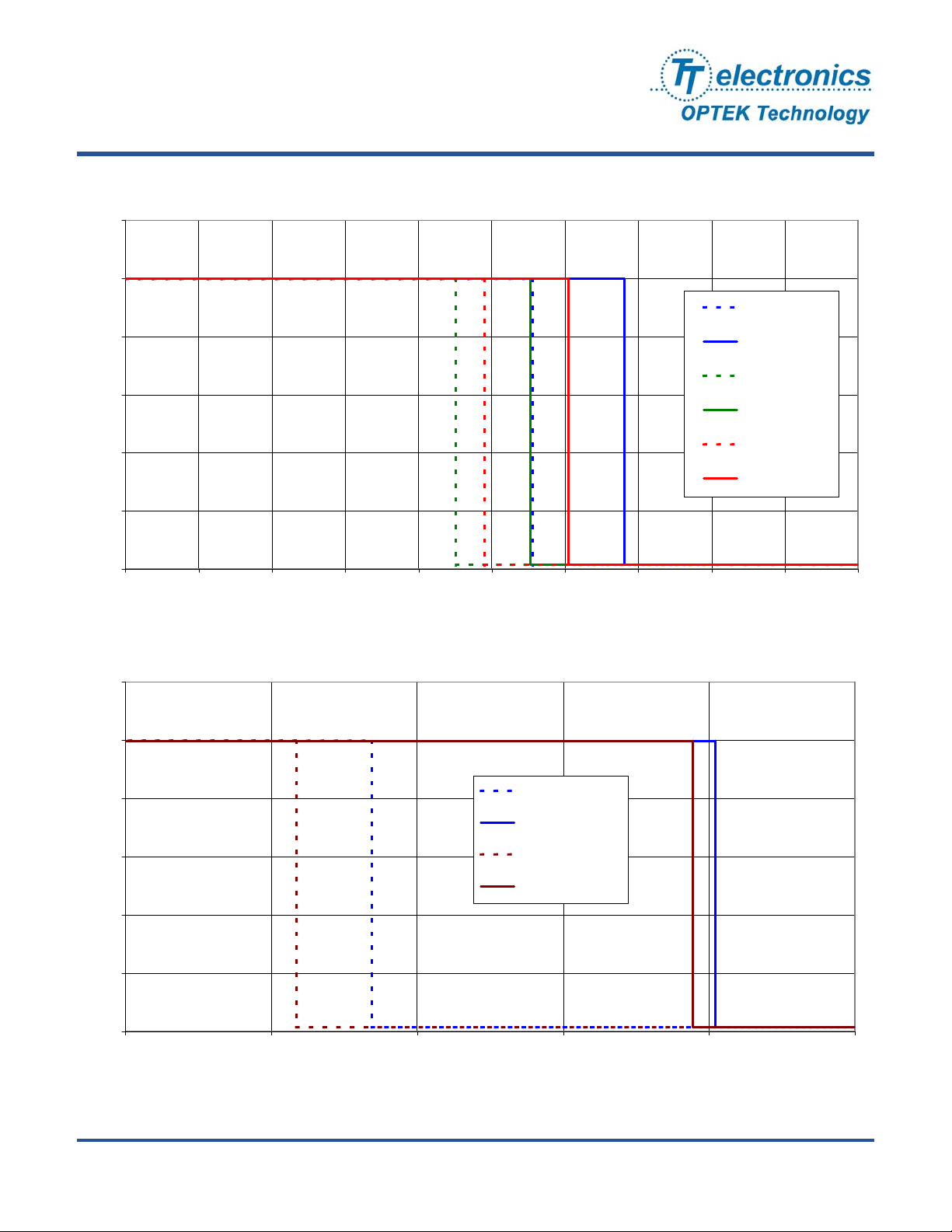
Voltage Response vs Displacement
OPB720A-06Z or OPB720B-06Z
12
10
8
OPB720A-06Z
Kodak 90% toward
Kodak 90% away
6
4
Typical Response Voltage
2
0
0'' 2'' 4'' 6'' 8'' 10''
Coporate toward
Coporate away
Avery 5160 toward
Avery 5160 away
Typical Displacement (inches)
Voltage Response vs Displacement
12
OPB720A-06Z or OPB720B-06Z
10
8
6
4
OPB720A-06Z
Nippon Crystallite toward
Nippon Crystallite away
3M 3870 toward
3M 3870 away
Typical Response Voltage
2
0
40'' 45'' 50'' 55'' 60'' 65'' 70''
Typical Displacement (inches)
OPTEK reserves the right to make changes at any time in order to improve design and to supply the best product possible.
OPTEK Technology Inc. — 1645 Wallace Drive, Carrollton, Texas 75006
Phone: (972) 323-2200 or (800) 341-4747 FAX: (972) 323-2396 sensors@optekinc.com www.optekinc.com
Issue F 07/07
Page 3 of 5
Page 4
Long Distance Reflective Switch
OPB720A and OPB720B Series
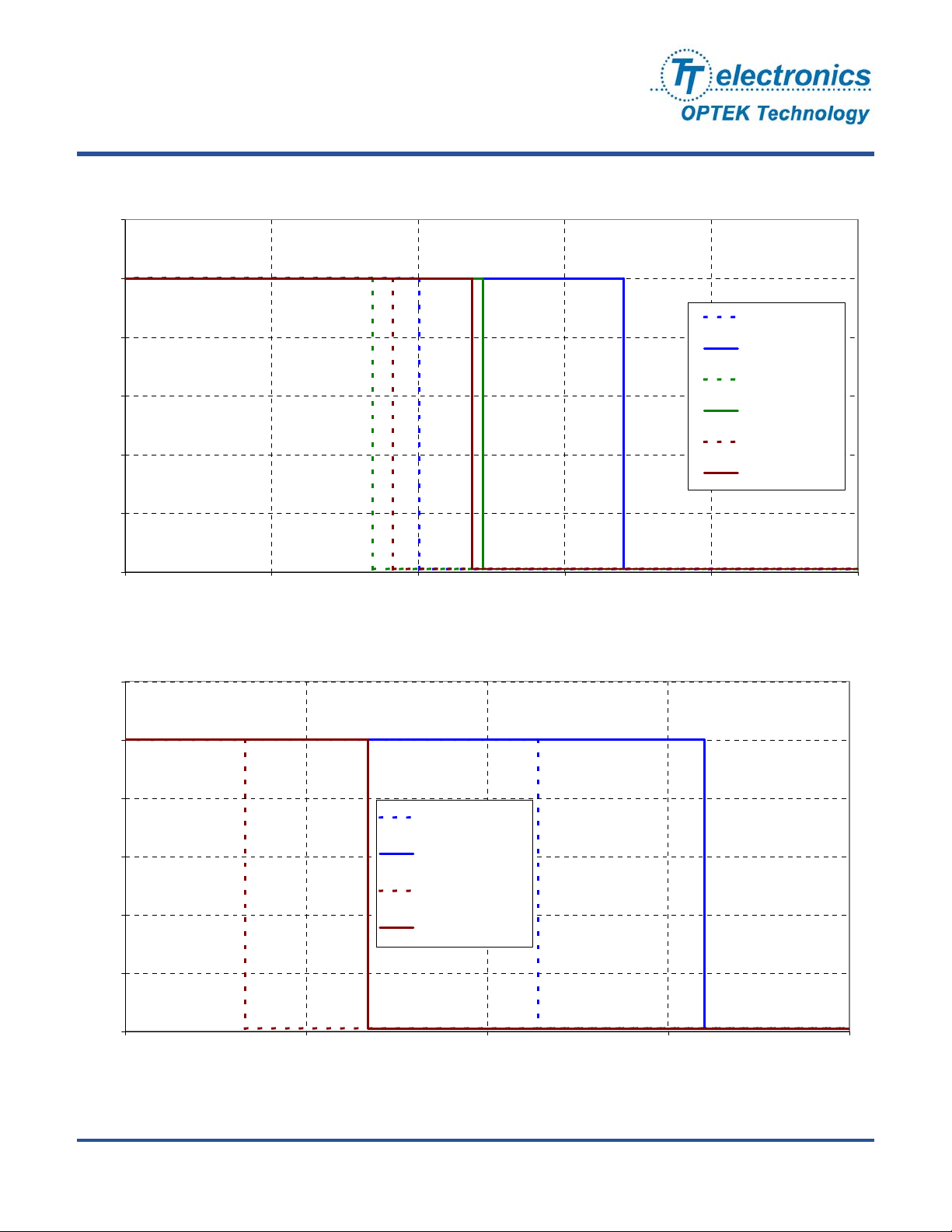
Voltage Response vs Displacemnent
OPB720A-12Z or OPB720B-12Z
12
10
OPB720A-12Z
Kodak 90% toward
8
6
4
Typical Response Voltage
2
0
0'' 2'' 4'' 6'' 8'' 10'' 12'' 14'' 16'' 18'' 20''
Kodak 90% away
Copy Paper toward
Copy Paper away
Avery 5160 toward
Avery 5160 away
Typical Displacement (inches)
Voltage Response vs Displacemnent
12
OPB720A-12Z or OPB720B-12Z
10
OPB720A-12Z
8
6
4
Nippon Crystallite toward
Nippon Crystallite away
3M 3870 toward
3M 3870 away
Typical Response Voltage
2
0
60'' 70'' 80'' 90'' 100'' 110''
Typical Displacement (inches)
OPTEK reserves the right to make changes at any time in order to improve design and to supply the best product possible.
Issue F 07/07
Page 4 of 5
Phone: (972) 323-2200 or (800) 341-4747 FAX: (972) 323-2396 sensors@optekinc.com www.optekinc.com
OPTEK Technology Inc. — 1645 Wallace Drive, Carrollton, Texas 75006
Page 5
Long Distance Reflective Switch
OPB720A and OPB720B Series
Voltage Response vs Displacemnent
OPB720A-30VZ or OPB720B-30VZ
12
10
8
6
OPB720A-36VZ
90% Kodak Towards
90% Kodak Away
Copy Paper Towards
Copy Paper Away
4
Normalized Output Level
2
0
25'' 30'' 35'' 40'' 45'' 50''
Avery 5160 Towards
Avery 5160 Away
Typical Switching Distance ( inches)
Voltage Response vs Displacemnent
12
OPB720A-30VZ or OPB720B-30VZ
10
8
6
4
Normalized Output Level
OPB720A-36VZ
Nippon Crystallite Towards
Nippon Crystallite Away
3M 3870 Towards
3M 3870 Away
2
0
120'' 145'' 170'' 195'' 220''
Typical Switching Distance (inches)
OPTEK reserves the right to make changes at any time in order to improve design and to supply the best product possible.
OPTEK Technology Inc. — 1645 Wallace Drive, Carrollton, Texas 75006
Phone: (972) 323-2200 or (800) 341-4747 FAX: (972) 323-2396 sensors@optekinc.com www.optekinc.com
Issue F 07/07
Page 5 of 5
 Loading...