

Page 1

Operations Technology, Inc.
OPTEK DPL-24 Users Guide
Operations Technology Inc.
30 Lambert Road
PO BOX 408
Blairstown NJ 07825
Phone 908 362-6200 • Fax 908 362-5966
1
Page 2

OPTEK DPL-24
Table of Contents
Introduction 4
Overview 5
Principles of Operation 6
Site Requirements 8
Specifications 9
Installation 10
Operation 12
Example 13
Precautions 14
Maintenance 14
Recommended Spare Parts 16
Ordering Information 16
Warranty 18
Index 19
3
Page 3

OPTEK DPL-24
V
A Differential Pressure Laminator
INTRODUCTION
he DPL-24 Differential Pressure Laminator has been designed to give the
operator a superior method for laminating sheet supported emulsions such
T
thicknesses and sizes of substrates. Experimentation is being done on alternative
uses for this device, among them, High Vacuum, Multi-Layer, Pressing of Printed
Circuit Boards and microBGA interconnects.
The substrate, prelaminated either manually, or utilizing the
A cold-roll lamination technique, is placed on the vulcanized rubber
platen mounted in the drawer
and positioned in the vacuum
chamber. Products of
differing thicknesses and
geometries can
be intermixed during a cycle if
adequate “hold-down”
techniques are employed.
The massive 1000 LB
chamber is constructed of
Ductile Iron and uses only
two o-rings. This design
ensures a positive seal for best
vacuum performance.
Utilizing a high quality, high volume 45 CFM, 3 horsepower, rotary
vane vacuum pump, an end point below two Torr is typically achieved.
as dry film solder mask, etc. Such materials can be applied to various
acuum lamination of printed circuit boards has been utilized
for many years. But it was not until the development of the
DPL-24 that a system provided vacuum prior to the
application of positive pressure.
No pressure is applied to the product during the vacuum
dwell cycle. In this way maximum evacuation of air from
between the substrate and the laminate is assured.
During the pressure cycle a flexible diaphragm encapsulates
the product and true isostatic lamination is achieved. Unlike
roll laminators, the DPL–24’s diaphragm descends directly
towards the platen. No lateral stress is applied , hence less
distortion of the film can occur.
4
Page 4

OPTEK DPL-24
OVERVIEW
• The vacuum is displayed on a thermocouple sensing, computer calibrated, digital
gauge located on the front panel.
• The substrate is exposed to this Vacuum Dwell for a time determined by a
precision digital timer which is adjustable from .1 seconds to 9990 hours.
• At the end of the Vacuum Dwell, a preheated silicone rubber diaphragm
descends onto the work-piece and drives the spring-mounted drawer
mechanism into intimate contact with the lower heater platen.
• The temperatures of both the upper and lower heat platens are controlled
independently by digital, proportional, Temperature Controllers.
• A positive pressure of up to 10 PSI is applied to the top of the diaphragm to
bring the combined differential to nearly 25 PSI.
• The Pressure Dwell is adjusted by a precision digital timer identical to that
employed by the Vacuum Dwell.
• Upon completion of a cycle, the drawer mechanism is retracted and the
product(s) removed for further processing.
• The entire process is governed by a microprocessor driven programmable
controller. Programming modifications are available from the factory.
5
Page 5

OPTEK DPL-24
PRINCIPLES OF OPERATION
The following is an explanation and diagram
of the operation of the DPL-24 differential pressure laminator.
When the DPL-24 is turned on, two proportional controllers independently
drive the top and bottom heaters to the heat the diaphragm and platen to the
temperatures set on the front panel. After a brief warmup time, the laminator is
ready for use.
The drawer is pulled open to allow access to load the vulcanized rubber platen
with materials ready for lamination. Products of differing thicknesses and
geometries can be intermixed during a cycle if adequate “hold-down” techniques
are employed. The layered material is placed on the platen mounted in the
sliding drawer. When the drawer is closed, the platen is positioned in the
vacuum chamber, and an O-ring seal on the drawer face contacts the opening in
the vacuum / pressure vessel.
Before the beginning of the cycle there is a vacuum drawn above the
diaphragm. Air at atmospheric pressure is in bottom of the vessel, pushing the
diaphragm upwards. As shown in figure 1, the diaphragm is up above the material
on the drawer platen. The drawer platen is spring loaded upwards to allow the
drawer to be opened and closed.
6
Page 6

OPTEK DPL-24
PRINCIPLES OF OPERATION (CONTINUED)
When the cycle starts, vacuum is drawn on both ports, above and below the diaphragm.
Utilizing a high volume vacuum pump, an end point approaching two Torr is achieved.
This vacuum is displayed on a digital gauge located on the front panel. A programmable
timer adjustable from .1 seconds to 9990 hours determines the vacuum dwell time before
continuing to the next step Figure 2. It is important to note that this dwell time will
allow air between the layers of material to be evacuated before the lamination pressure
cycle begins, eliminating trapped bubbles. Because the vacuum is equal above and below
the diaphragm, it does not move and does not contact the material in the drawer.
At the end of the Vacuum Dwell, positive air pressure at up to 10 PSI is
applied to the port above the diaphragm bringing the pressure differential to nearly
25 PSI. see figure 3, The preheated silicone rubber diaphragm descends onto the
workpiece. This action drives the spring-mounted drawer platen into contact with
the lower heater platen. Isostatic pressure is transferred to the material by the
diaphragm. The stretching effect that occurs with roll type laminators is minimized.
The flexible diaphragm conforms to the surface shape assuring positive contact
between the layers, thereby eliminating voids. The pressure dwell time is controlled
by another timer identical to the vacuum dwell timer.
7
Page 7

OPTEK DPL-24
PRINCIPLES OF OPERATION (CONTINUED)
At the end of the pressure dwell cycle, the top port is connected to the
vacuum pump again, and the bottom port is vented to atmospheric pressure. As shown
in figure 4, this returns the diaphragm and drawer platen to their original positions and
allows the drawer to be opened for unloading.
SITE REQUIREMENTS
Dimensions: 44" Wide X 44" Deep X 60" High, exclusive of leveling feet (1" to 2")
Weight: 2,200 LBS (shipping)
Electrical Requirements: 208/220 VAC, 3 Phase, 40 Ampere/Phase
Compressed Air: Dry, Filtered, 70 PSI, 3 CFM
8
Page 8

OPTEK DPL-24
SUBSTRATE SPECIFICATIONS
Productivity:
Cycle time is adjustable from 0 to infinity and is determined by application
parameters such as circuit complexity, ground plane areas, circuit heights, flow
temperatures, etc. Typical times for a dry-film solder mask application would be 30
seconds for Vacuum Dwell and 20 seconds for Pressure Dwell.
Substrate size:
Items up to 24" X 24" can be laminated. Smaller substrates can be
processed in multiples if space permits and can be intermixed providing adequate
hold-down techniques are observed.
Substrate Thickness:
Thicknesses from .001" to .375" can be accommodated though standard
board hold-down bars .
9
Page 9
OPTEK DPL-24
INSTALLATION
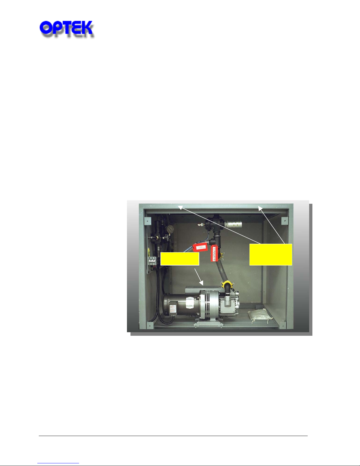
Due to the weight of the unit a forklift is mandatory for removal of the
DPL-24 from the pallet and, for final positioning.
1. Upon receipt of equipment inspect for obvious external damage.
2. Remove Tri-Wall cardboard box or wooden crating and inspect for damage to
the machine itself. Do not attempt to slide the chamber drawer.
3. Using a forklift roughly place the DPL-24 utilizing the attached pallet,
4. Remove lower back panel
5. Remove the four bolts securing unit to pallet.
6. Raise unit with forklift blades positioned under main vessel, being careful not to
damage main valve. (see illustration below)
7. Install leveling feet
(included) into
threaded holes
formerly occupied by
shipping bolts.
8. Position, lower, and
level the unit.
9. WARNING: IT IS
IMPERATIVE
THAT OIL BE
ADDED TO PUMP
BEFORE
OPERATION!
ROTATION
LIFT HERE
10
Page 10

OPTEK DPL-24
INSTALLATION (CONTINUED):
10. Supply Compressed Air to input nozzle on right side rear of the machine.
11. Adjust primary regulator to 50-80 PSI.
12. Adjust secondary regulator to 5-10 PSI.
WARNING: DO NOT ATTEMPT TO ADJUST
REGULATOR PAST STOP!!!
DO NOT REMOVE PIN UNDER ANY CIRCUMSTANCES!!!
13. Ensure that switch on pump
14. Wire and Connect 220 VAC, 3 Phase, 40 Ampere power to input cable.
15. Activate “Main Power” switch on front panel.
16. Momentarily depress “Emergency Reset” switch on front panel.
17. Activate “Vacuum Pump” switch on front panel.
18. With one person at switch and one person at the pump, “JOG” the vacuum
pump switch and monitor the pump to ensure proper rotation indicated by the
arrow found on motor end case.
Note: If the rotation is opposite to that indicated,
reverse any two phases of incoming power.
19. Upon determination of proper pump rotation, leave pump mounted switch in
“`ON” position.
is in the “OFF” position.
Your DPL-24 unit is now
ready for operation.
11
Page 11

OPTEK DPL-24
OPERATION
1. Insure circuit breaker is in the “ON” position.
2. Activate “MAIN POWER” switch.
3. Activate “VACUUM PUMP” switch.
4. Chamber drawer may now be opened for inspection.
WARNING: PLATEN MUST BE IN POSITION WHEN CYCLING
MACHINE!
5. Return drawer to home position.
6. Activate “TOP” and “BOTTOM” Heaters by depressing and
illuminating switches beneath digital controllers.
7. Press "asterisk" and
"up" or "down" arrows
until desired
temperature is indicated
on digital readout.
8. Release "asterisk" and
note temperature
indication on readout.
9. A flashing green light below the temperature readout indicates the controller is
triggering the solid state relay to supply current to the respective heater blanket.
10. Allow 20-40 minutes for unit to reach set-point and stabilize, if (under 200
degrees F).
11. Product may now be processed through laminator.
12
Page 12

OPTEK DPL-24
OPERATION EXAMPLE
1. Set both Temperature Controllers to 160 Degrees F.
2. Set Vacuum Dwell to 30 Seconds.
3. Set Pressure Dwell to 20 Seconds.
4. Place Prelaminated product on Platen.
5. Slide Hold-Down Device into place.
6. Slide Drawer into Vessel.
7. Momentarily depress the “CYCLE START” button.
8. Machine will complete one “AUTOMATIC CYCLE”.
9. “CYCLE READY” Light Illuminates.
10. Slide the drawer out, and remove substrate.
NOTE: If at any time the operator desires to exit the cycle, depress the “CYCLERESET” button and machine will return to Step 0. Atmospheric pressure will be
vented to the chamber and the drawer may be opened.
NOTE: If at any time the operator wishes to hold the cycle at a given step, depress
the “CYCLE STOP” button. The machine program will hold at the present step
indefinitely. To resume the program sequence, press “CYCLE START” button.
NOTE: If the operator wishes to step through the program manually, depress the
“SINGLE STEP” button. Unit will advance one program step with each pressing
of the button, maintaining that step’s conditions after completion of the timer
setting.
13
Page 13

OPTEK DPL-24
PRECAUTIONS
CAUTION: NEVER ATTEMPT TO REMOVE DRAWER FROM
VESSEL WITH VACUUM PUMP OFF. EMERGENCY RESET
BUTTON MUST BE DEPRESSED. IN STEPS OTHER THAN STEP 0,
VACUUM IS APPLIED TO THE DOOR AND WITHDRAWAL IS
IMPOSSIBLE.
IF VACUUM PUMP IS OFF, THE DIAPHRAGM MAY BE IN
CONTACT WITH THE VULCANIZED PLATEN AND PERSISTENT
PULLING MAY CAUSE DAMAGE.
MAINTENANCE
Vacuum Pump - The 45 CFM, Rotary Vane, Vacuum Pump is supplied to you with
no oil installed. The oil should be changed after every 500 hours of operation and
is available directly from Operations Technology Inc.
WARNING: IT IS IMPERATIVE THAT OIL BE ADDED TO PUMP
BEFORE OPERATION!
NOTE: A separate manual for the pump has been included and all maintenance
directives therein should be adhered to.
Vacuum Gauge -
The 0 - 20 Torr
Solid State
Vacuum Gauge is
a precision,
rugged, device
used to constantly
monitor the
vacuum present
in the vacuum
chamber. A level
approaching two
Torr or better
indicates proper machine operation.
14
Page 14

OPTEK DPL-24
MAINTENANCE
Digital Proportional Temperature Controllers
precise control of temperature for the upper and lower heater platens
independently. They are calibrated at the factory and should not
need further adjustment.
Programmable Controller and Power Supply - These units control
activation, deactivation, and timing of the various valves and lights
in the DPL. A program stored in memory is utilized to direct the
sequence of events. Custom programming can be accomplished by the
factory for specialized applications. Neither the controller nor the
power supply requires preventive maintenance.
Filter Regulator - Normally, clean, filtered, dry air should be supplied to the machine.
The DPL-24, however, has an additional filter incorporated into the primary
regulator. This filter requires minimal maintenance.(Open petcock and drain out
water occasionally! )
Diaphragm- The 50 Durometer, .125" thick, Silicone Rubber Diaphragm is the major
wear item in the system. It is advisable to keep a replacement Diaphragm on-hand
in the event of a puncture or rupture. This unit is available “pre-punched” from the
factory. Cleaning of the Diaphragm is accomplished with Isopropyl Alcohol only.
Platen- All work is pressed on this Vulcanized Rubber Platen. It is advisable to keep
a standby Platen on hand if replacement becomes necessary due to normal wear or
abrasion. Cleaning is accomplished either on or off the machine with a soft cloth,
moistened with Isopropyl Alcohol only.
- These devices provide
15
Page 15

OPTEK DPL-24
RECOMMENDED SPARE PARTS
PART # DESCRIPTION QUANTITY PRICE TOTAL
1007 CONTROL,TEMP,9900 1 PIECE $350.00/ea. $350.00
1008 HEATER, SILICONE 1 PIECE $450.00/EA. $450.00
1024 BULB, INDICATOR 4 PIECES $2.00/EA. $8.00
1026 DRAWER SLIDE, LARGE 1 PAIR $130.00/PR $130.00
1027 O' RING, DOOR 1 PIECE $38.00/EA. $38.00
1028 `O' RING, VESSEL 1 PIECE $30.00/EA. $30.00
1041 FAN, EXHAUST, 220V 1 PIECE $47.00/EA. $47.00
1042 RELAY, SOLID STATE 1 PIECE $53.00/EA. $53.00
1043 RELAY, MAIN 1 PIECE $120.00/EA. $120.00
1070 VALVE, ACTUATOR 1 PIECE $50.00/EA. $50.00
1077 DIAPHRAGM, 1 PIECE $300.00/EA. $300.00
1078 PLATEN, 24" X 24" 1 PIECE $300.00/EA. $300.00
1089 VACUUM PUMP OIL 5 GAL $15.00/GAL $75.00
1094 SPRING, DRAWER 4 PIECES $2.00/EA. $8.00
1113 BOARD HOLD-DOWN 1 PAIR $150.00/PR $150.00
1117 TIMER,DIGITAL 1 PIECE $125.00/EA. $125.00
TOTAL ...……… $2,234.00
Pricing shown is current at the time of publishing and is subject to change.
ORDER PARTS FROM:
OPERATIONS TECHNOLOGY INC.
#30 LAMBERT ROAD
P. O. BOX 408
BLAIRSTOWN, NJ 07825
Phone (908) 362-6200
FAX (908)362-5966
16
Page 16

OPTEK DPL-24
ALSO AVAILABLE FROM:
OPERATIONS TECHNOLOGY INC.
#30 LAMBERT ROAD
P. O. BOX 408
BLAIRSTOWN, NJ 07825
Phone (908) 362-6200
FAX (908)362-5966
17
Page 17

OPTEK DPL-24
WARRANTY
1. PERIOD OF WARRANTY:
Operations Technology Incorporated warrants this product to be
free of defects in material or workmanship for a period of 180
days commencing on the shipping date from Blairstown, New Jersey.
2. LIABILITY OF WARRANTY
Operations Technology Incorporated warrants to the original
purchaser that equipment sold under this agreement shall be free
from defects in material and workmanship. Defective materials
will be replaced or repaired at the discretion of Operations
Technology Incorporated. Liability will be determined by
Operations Technology Incorporated. All liability is expressly
limited to said repair or replacement of defective parts, all
other damages and warranties, statutory or otherwise, being expressly
waived by the purchaser. This warranty is null and
void if the equipment failure is due to negligence, accident,
abuse, or improper operation. It is also nullified by tampering,
alteration, or unauthorized repair of subject equipment or components.
This warranty does not include filters , oil , Platen, and
Diaphragm as they are generally considered to be consumable items.
The user shall return all allegedly defective materials to
Operations Technology Incorporated via approved routing, charges
prepaid. Upon determination of liability, Operations Technology
Incorporated will either submit a quotation for repairs or
rectify the defect at no charge.
This warranty cannot be countermanded by the purchaser and is the
only warranty relative to the transaction. No other warranty,
expressed, implied or statutory shall apply.
Effective Date 1/1/96
Revised 6/1/2004
18
Page 18

OPTEK DPL-24
O
A
Index
air.............................................. 6, 7, 8, 11, 15
AUTOMATIC CYCLE ........................... 14
B
Bubbles ......................................................... 7
C
CYCLE READY....................................... 14
CYCLE- RESET....................................... 14
CYCLE START ........................................ 14
CYCLE STOP........................................... 14
Cycle time................................................... 10
D
diaphragm........................................ 5, 6, 7, 9
Digital controllers...................................... 13
dimensions ................................................... 9
dwell time ..................................................... 7
E
Electrical....................................................... 9
Emergency Reset....................................... 12
Experimentation.......................................... 4
H
Heaters........................................................ 13
hold-down ..........................................4, 6, 10
O-ring seal .................................................... 6
P
PARTS ........................................................17
Precautions .................................................14
Pressure Dwell ................................ 5, 10, 14
Programming................................................5
R
Rotation ......................................................11
Rubber platen...............................................6
S
sequence............................................... 14, 16
SINGLE STEP..........................................15
Specifications................................................9
Stretching effect...........................................7
substrates ................................................4, 10
T
Temperature Controllers ............... 5, 14, 16
Thicknesses.................................................10
V
vacuum chamber....................................4, 15
Vacuum Dwell ............................5, 7, 10, 14
vacuum pump ...............................4, 7, 9, 12
M
Maintenance............................................... 14
W
Warranty .....................................................18
Weight .....................................................8, 18
19
 Loading...