

Page 1
Page 1
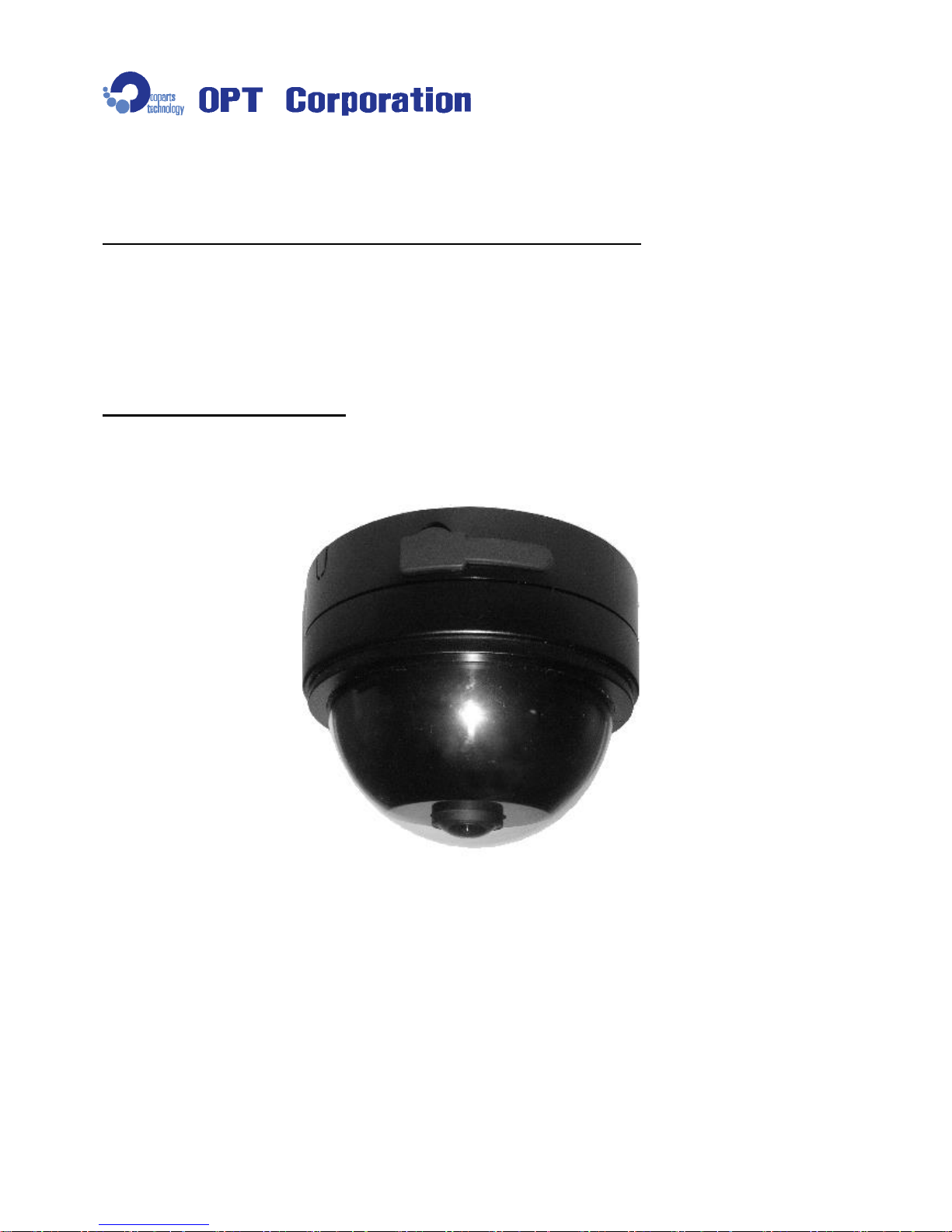
360 degree Omnidirection Camera
Dome Type Model : NM33D-F
User’s Manual
Thank you very much for purchasing the 360 degree omnidirection camera
NM33D-F. Please read this manual carefully before using the product for
proper operation. Preserve this manual and use this when it is necessary.
◆ The description may be modified without any notice.
V. 1.30
Page 2
Page 2
For Safety Use – Warning
Please read this manual carefully before using the product for proper operation.
The followings are very important notices for the safety use of the product. Make sure to follow the instructions
described here.
Neglecting the instruction may cause death or
serious injury.
• If smoke or nasty smell is observed from the unit, unplug Power Cable of the AC Adaptor
immediately. Otherwise it may cause electric shock or fire.
• Use only the AC Adaptor (5V, 2A) and the USB Cable originally supplied with the product.
Otherwise the product can not work properly or cause electric shock or fire.
• Do not let water or foreign items in the unit. If it happens, turn the power off immediately and
unplug Power Cable. Otherwise it may cause fire or electric shock.
• Do not damage Power Cable or AC Adaptor. Otherwise it would cause fire or electric shock.
- Do not modify or and repair Power Cable or AC Adaptor.
- Do not squeeze Power Cable in a wall or a cabinet.
- Do not place heavy items on or drag Power Cable.
- Do not heat Power Cable or AC Adaptor as placing near thermal appliances.
- When unplug AC Adaptor from the wall outlet, hold its body to pull.
• When Power Cable or AC Adaptor is damaged, or the plug is loose, do not use it.
Otherwise it may cause electric shock, short circuit, or fire.
• Make sure to plug firmly. Otherwise it may cause fire or electric shock.
• Remove dust on the plug by using a dry cloth. Otherwise it may cause fire.
• Do not place the product in following places. Otherwise it may cause fire or malfunction.
- Place near fire or full of hot-air
- Direct sunlight
- Poorly-ventilated space
- Place with humid and dust
- Place where ventilating hole is closed
- Place not flat or uneven
- Place where a lot of vibrations exist
• Do not place heavy items on the unit. Otherwise it may cause damage or malfunction.
• Do not touch the unit or the plug when lightning starts. Otherwise it may cause electric shock.
• Do not disassemble or modify the unit. Otherwise it would cause fire, electric shock or
malfunction.
!
Warning
Page 3
Page 3
For Safety Use – Caution & Remarks
Neglecting the instruction may cause risks of injury
or property damages.
• Installation or wiring of the product must be done with the power off. Unplug Power Cable
surely before taking proper care for the unit. Otherwise it may cause fire, electric shock, or
injury.
• Don’t use the product under the circumstance beyond the product specified range.
• Don’t use the product near the device to generate the electric noise.
• Please acknowledge beforehand that OPT Corporation is not responsible for any claims
such as the losses and passive damages in which the operation of this product is assumed
to be a reason.
• OPT Corporation is not responsible for any loss or missing of the taking image.
• Don’t block the product with other items from the easiness for the maintenance and the heat
radiation purpose.
• Please use the AC Adaptor (5V, 2A) or the USB Cable originally supplied with the product.
Otherwise, OPT Corporation does not warrant the feature and performance of the product.
• Without any notice, the product might be improved or changed in parts or design.
• If you use AC Adaptor and USB Cable simultaneously as a power source, connect AC
Adaptor first to supply the power to the camera, then connect USB Cable. When unplug,
disconnect USB Cable first, then AC Adaptor.
• If the camera lens or Dome Cover becomes dusty or oily, the image may be garbled. Use a
soft close with the lens cleaner to wipe the dust or oil off.
Other Remarks
!
Caution
Page 4
Page 4
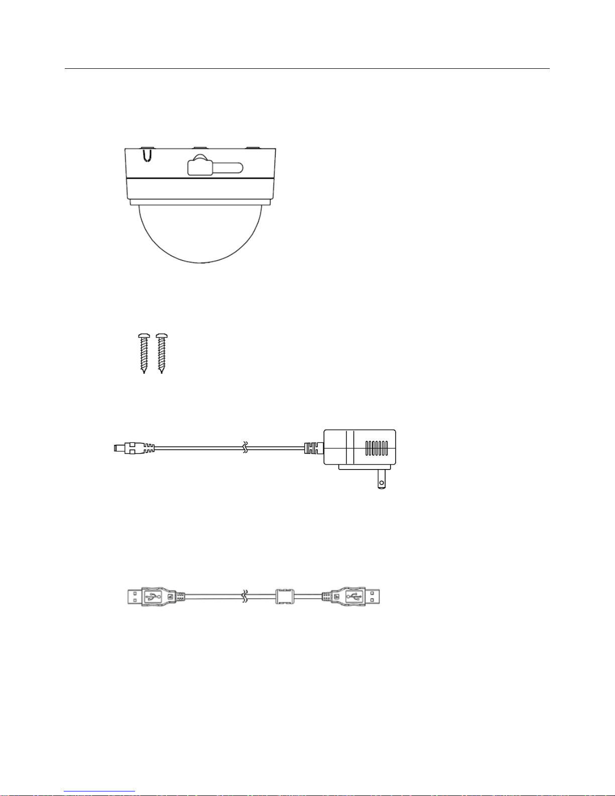
1.Contents
(1) Camera (NM33D-F) : 1 pc
(2) Camera Fixing Screw (3.5 × 20) : 2 pcs
(3) AC Adaptor (5V2A) : 1 pc
Caution: Use only the AC Adaptor (5V, 2A) originally supplied with the product.
(4) USB Extension Cable (3 m) : 1 pc
Note: According to the package you purchase, other accessories may be enclosed. Please
refer to the instruction included in the package.
Page 5
Page 5
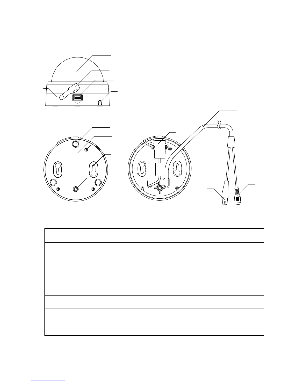
2.Name of Part
Name of Part
① Dome Cover
⑧ Bottom Cover Fixing Screw (3 places)
② Dome Base
⑨ Screw Hole (2 places)
③ USB Packing
⑩ Camera Tripod Screw Mount
④ USB Socket
⑪ USB Socket Holder
⑤ Cable Gate
⑫ BNC/DC Cable
⑥ Rubber Foot(3 places)
⑬ BNC Connector(Male)
⑦ Bottom Cover
⑭ Power Connector (for AC Adaptor)
①
③
④
⑤ ⑦ ⑨ ⑩ ⑫ ⑬ ⑭
《 view with Bottom Cover on 》
⑥ ② ⑧
⑪
《 view with Bottom Cover off 》
Page 6
Page 6
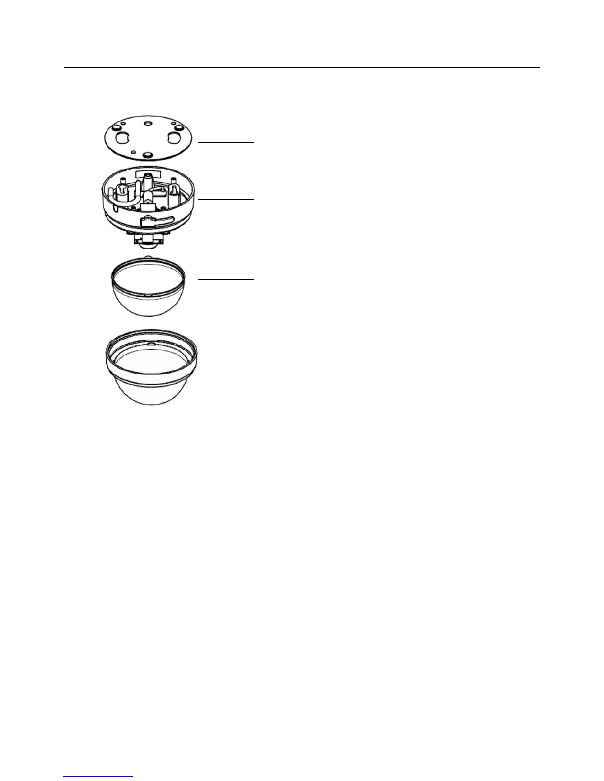
3.Construction of Camera
① Bottom Cover
This is necessary to place the camera on the table. Remove it when installing the
camera on the wall or under the ceiling.
② Dome Base
Camera Module, BNC/DC Cable and else are mounted on this base.
③ Dome Inner Cover
The protect cover for Camera Module.
④ Dome Cover
The protect cover for Camera Lens.
① Bottom Cover
② Dome Base
④ Dome Cover
③ Dome Inner Cover
Page 7
Page 7
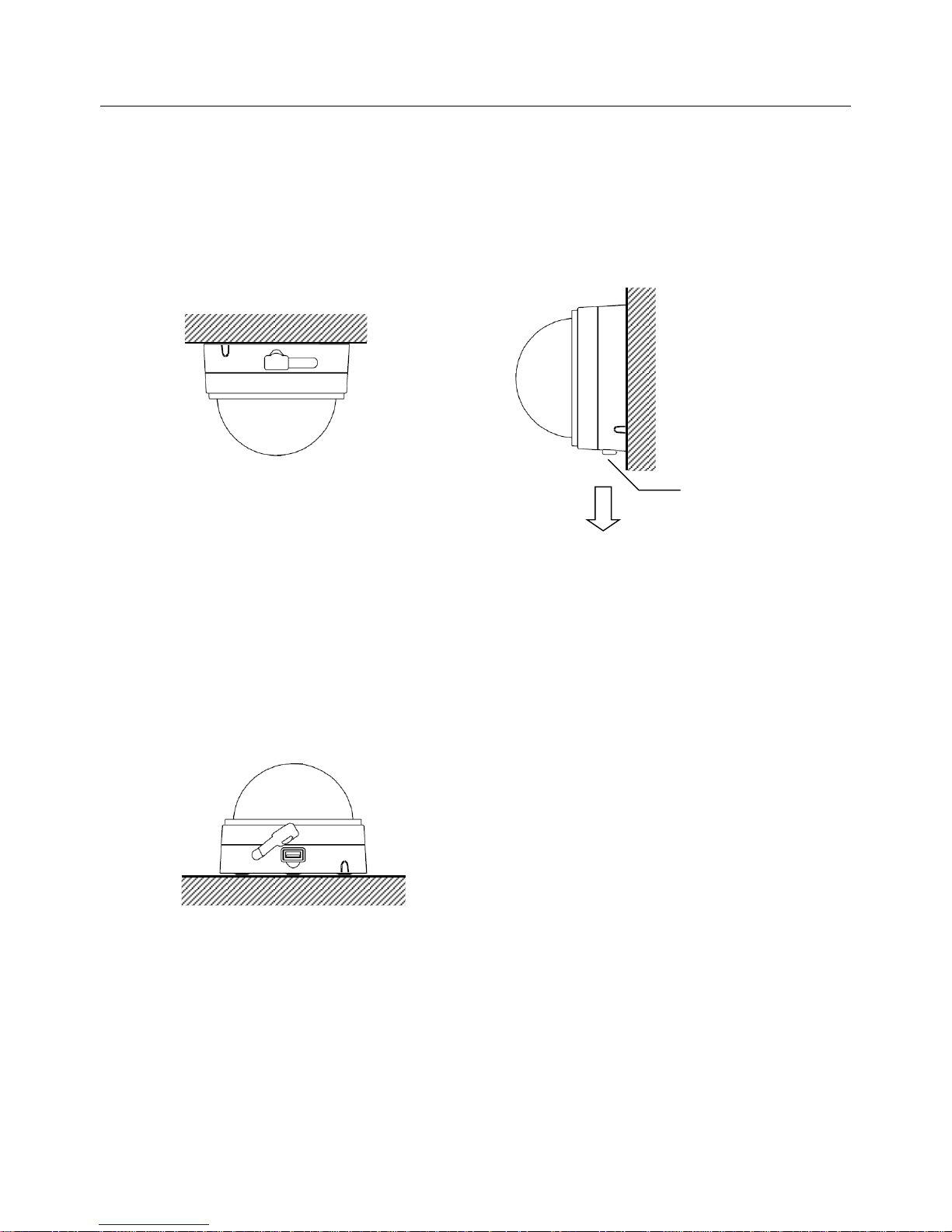
4.Advice for Installing Camera
① when Installing on the wall or under the ceiling
Remove Bottom Cover when installing the camera on the wall or under the ceiling.
Please refer to the section 6 for the installation.
For the Installation vertically, align USB Packing downward.
② when placing on the table (for the TV conference use)
When using the camera placing on the table, store BNC/DC Cable into Dome Base and
attach Bottom Cover on.
Note: For the TV conference use, a PC and the recorder software are necessary.
USB Packing
(Ceiling)
(Wall)
( on the table use )
Downward
Page 8
Page 8
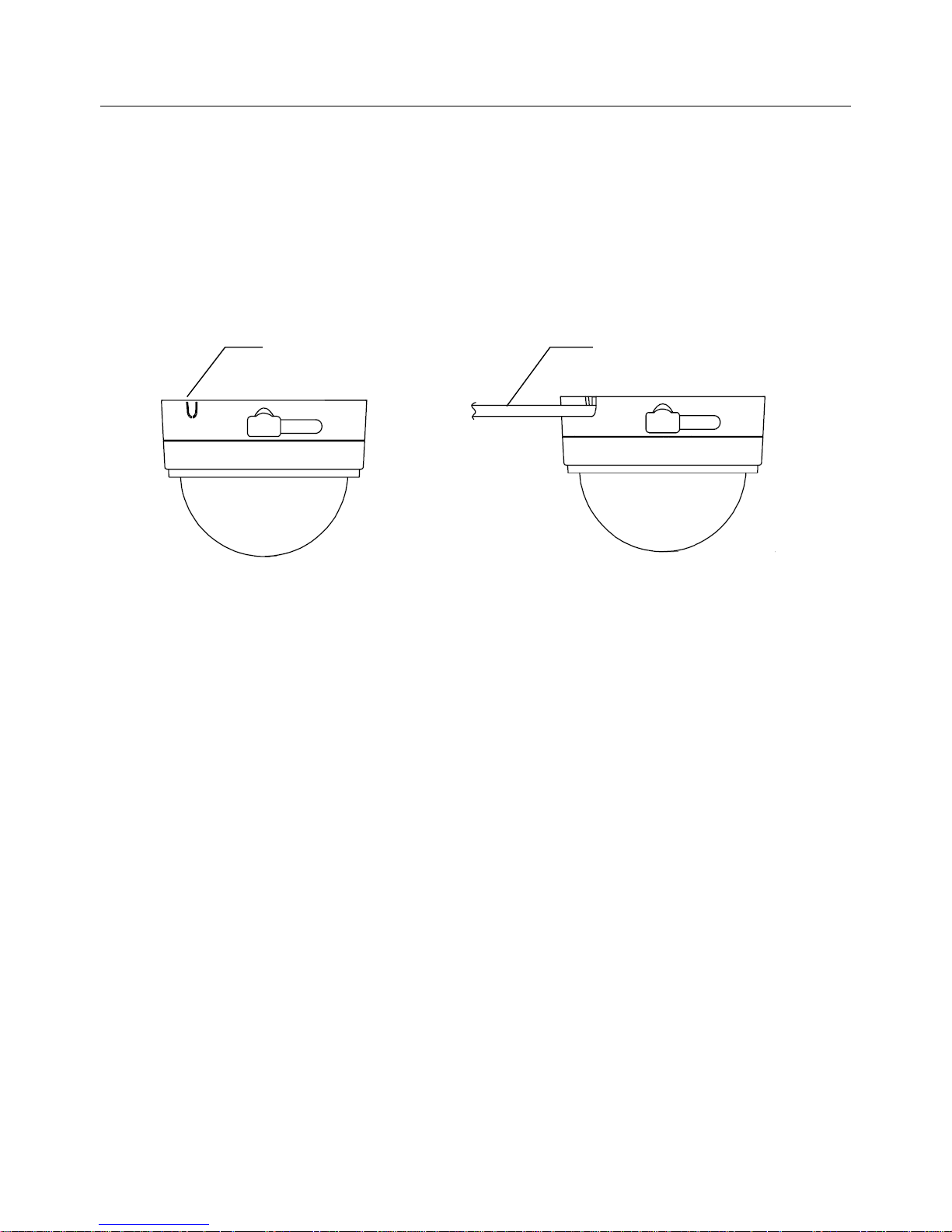
5.Advice for Cable Lining
In a normal case, BNC/DC Cable would like to be located behind the camera bottom with
Bottom Cover taken off.
If installing the camera on a concrete wall (no room behind the wall), it is impossible to line the
cables behind the camera. In such the case, crack the plastic piece of Cable Gate and line the
cables from the side of camera.
Note 1: The plastic piece of Cable Gate can be removed by a nipper like tool. After remove
the plastic piece, clean burrs off from Cable Gate. If burrs are left, it may cause injure
or damage of the cable.
Note 2 : The plastic piece of Cable Gate can not be replaced after once removed.
Cable Gate
BNC/DC Cable
Page 9
Page 9
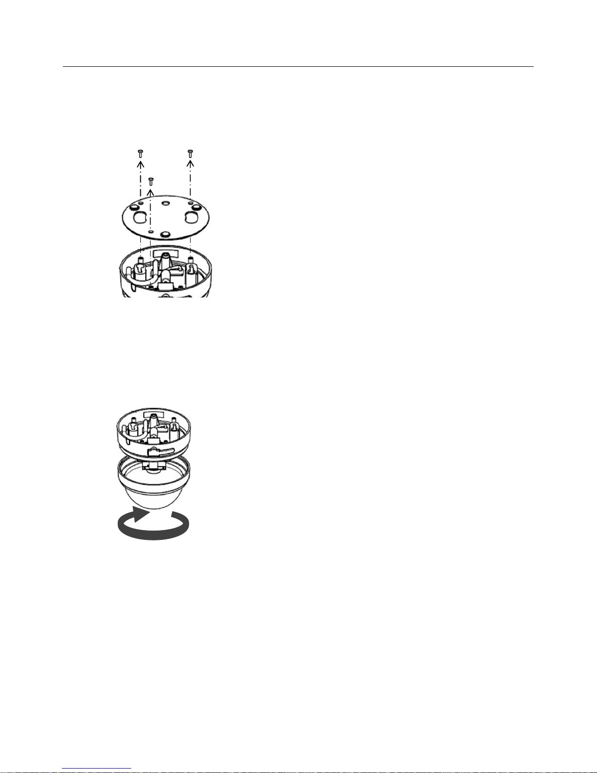
6.Installation (Ceiling, Wall) - Preparation
① Remove Bottom Cover
Remove Bottom Cover Screws and remove Bottom Cover from Dome Base.
② Remove Dome Cover and Dome Inner Cover
Hold Dome Cover and Dome Base firmly by hands, rotate Dome Cover counterclockwise to
remove Dome Cover from Dome Base.
Note: There is Dome Inner Cover inside of Dome Cover. Please pay attention not to drop
Dome Cover and Dome Inner Cover when removing.
Page 10
Page 10
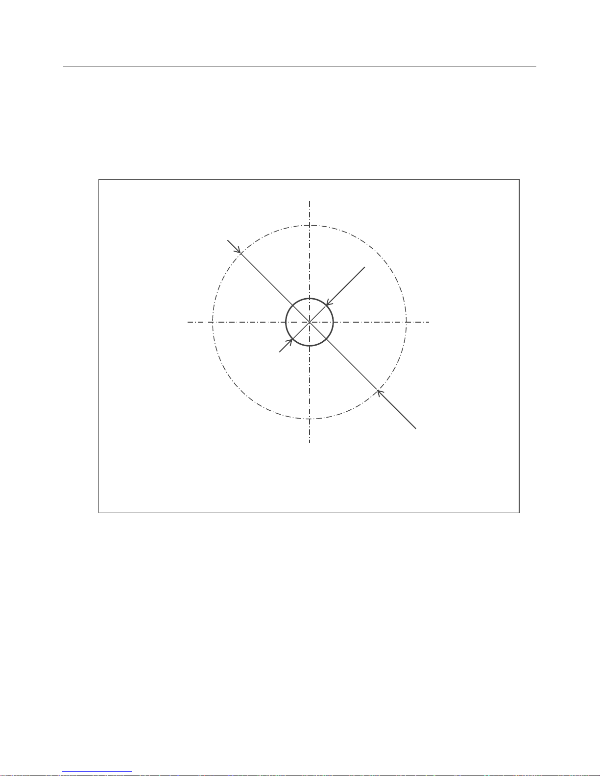
6.Installation (Ceiling, Wall) – Mark the install position
③ Mark at the place to install the camera and make a through hole for lining the cables.
Make a through hole of (Φ30mm)at the center of the place to install the camera.
Place to install (Ceiling or Wall)
Through hole (φ30 mm) to
line the cables
Outer diameter of the
camera (φ122.5 mm)
Page 11
Page 11
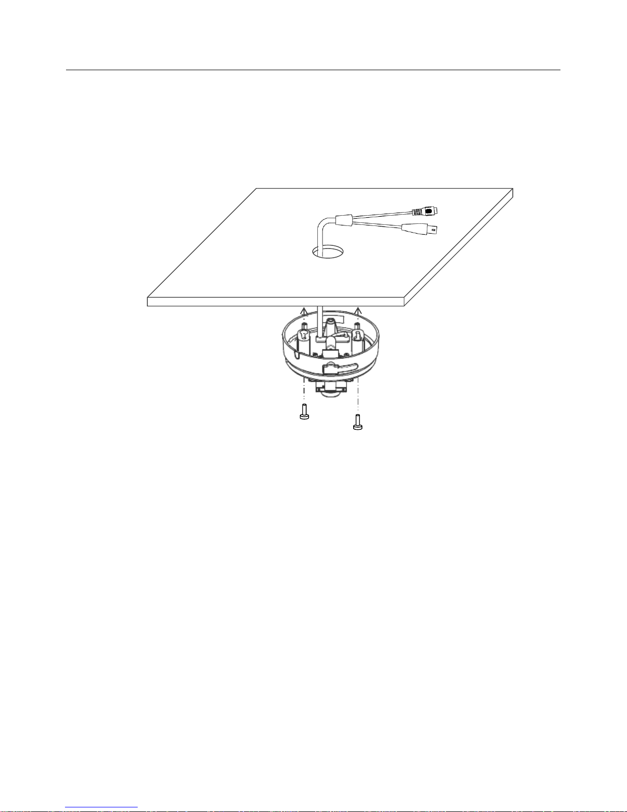
6.Installation (Ceiling, Wall) – Fixing the Camera
④ Line the cables in the hole and fix Dome Base
Lining BNC/DC Cable in the hole, push Dome Base against the installation surface, then fix
Dome Base to the ceiling or wall by Camera Fixing Screws.
Note 1: The Camera Fixing Screws provided with the camera are for the plaster board.
According to the material and the strength of the installation surface, use most
suitable screws (φ3.5~4.0 size).
Note 2: For the Installation vertically, align USB Packing downward.
Page 12
Page 12
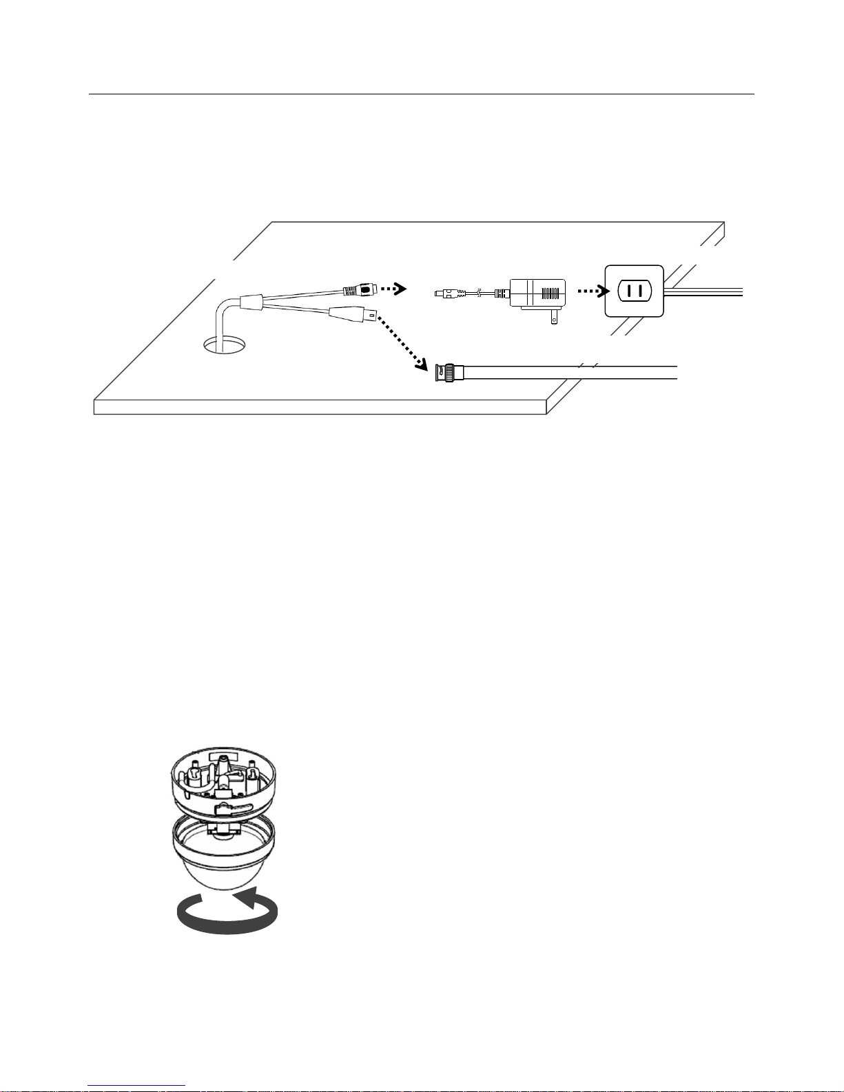
6.Installation (Ceiling, Wall) – Connecting Cables
⑤ Connect Signal and Power Connectors
Connect AC Adaptor and BNC cable to the connectors of BNC/DC Cable as shown in the
below figure.
Note 1: If excessive load is applied on the connection of BNC/DC Cable or AC Adaptor, the
power line may be disconnected. It is recommended to fix the connection firmly by
taping.
Note 2: As for the separate construction of the AC outlet and the BNC cable, make them with
sufficient length.
Note 3: Never connect the BNC/DC Cable to the superimposed cable where the
electric power is imposed on the signal line. Otherwise it will cause the
damage to the camera.
⑥ Install Dome Cover and Dome Inner Cover
Make sure whether Dome Inner Cover is in the right place of Dome Cover. Holding Dome
Cover and Dome Base firmly by hands, rotate Dome Cover clockwise to install the Dome
Cover.
Note : Align the ribs of Dome Inner Cover to recession of Dome Cover when placing Dome
Inner Cover into Dome Cover.
AC Adaptor
BNC/DC Cable
BNC female connector
(separate construction)
AC outlet
(separate construction)
Page 13
Page 13
7.Adjust Output Image
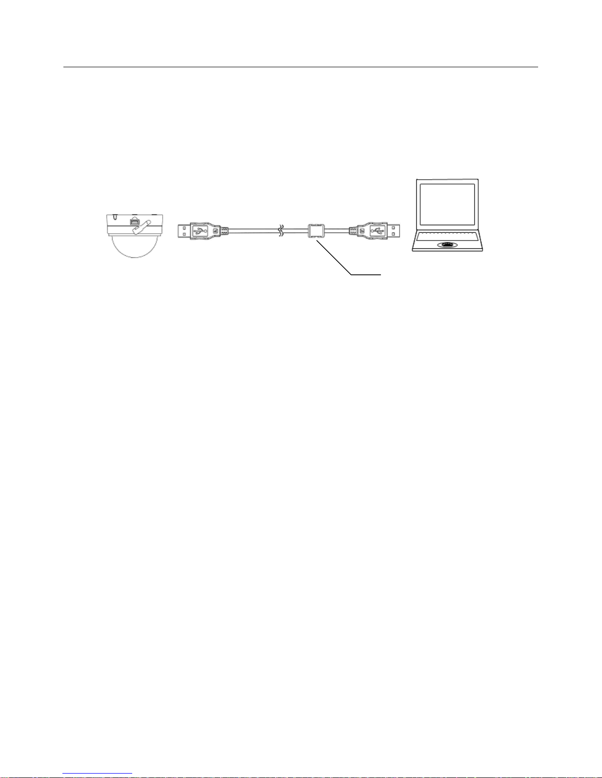
① Connect the camera to a PC
Connect the camera with a PC by the enclosed USB Extension Cable (between USB
Socket and the USB port of the PC.
Note 1: If using AC Adaptor simultaneously with USB power, supply of power from AC
Adaptor must be done before connecting USB Cable.
Note 2: When using USB Cable connecting with a PC, never plug on/off of AC Adaptor.
Note 3: USB Extension Cable must connect to the PC with the Ferrite Core side to the PC.
Note 4: For the first connection of the camera to a PC, installation of the driver software to
the PC is required. Please refer to the software manual for detail.
② Adjust Output Image
The image dewarping software is pre-installed in the camera. The software works for the
output image adjustment and the pre-setting (store the initial setting).
Please refer to the software manual for the manner to install the software and its operation.
PC for adjustment
Enclosed USB Extension Cable
Camera
Ferrite Core
Page 14
Page 14
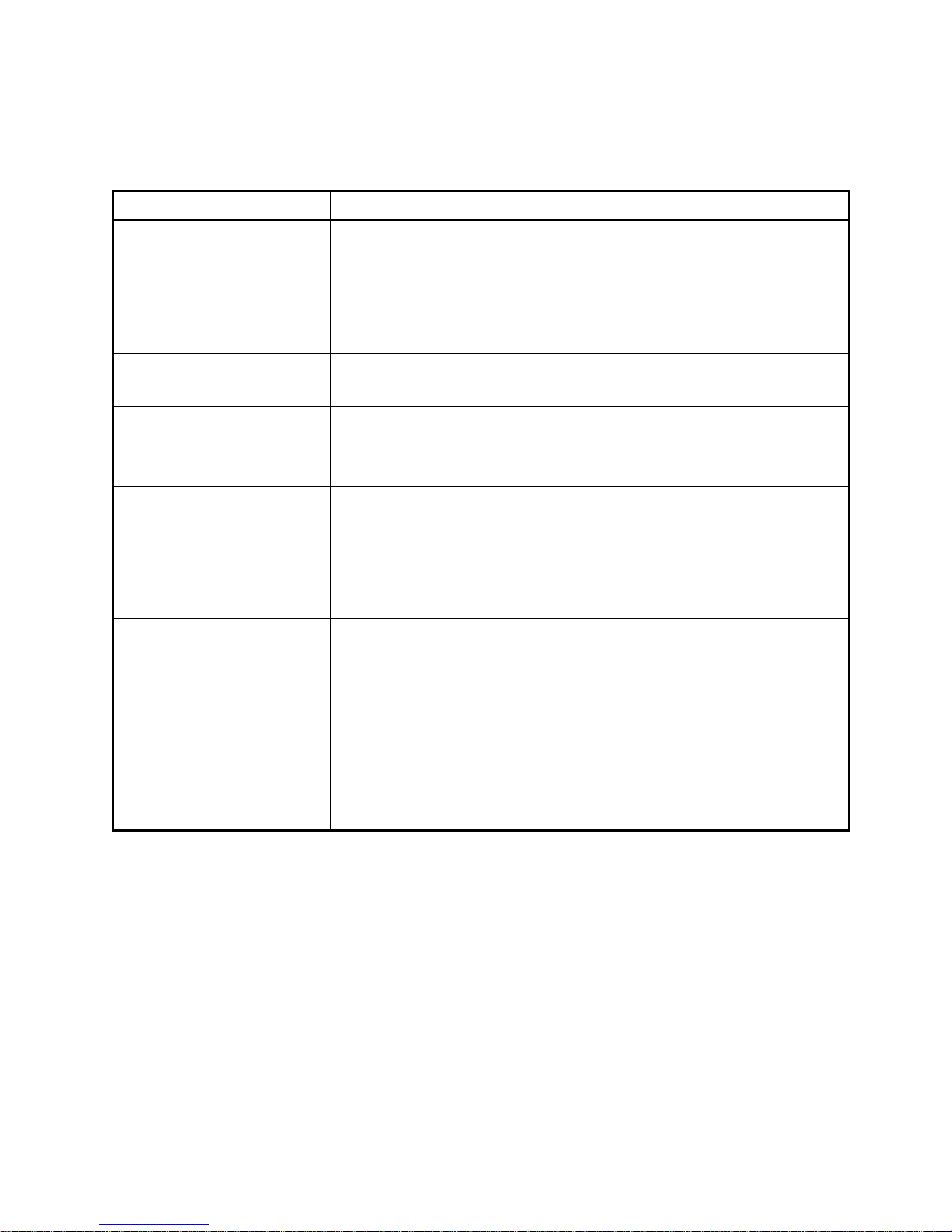
8.Trouble Shooting
If you are facing any trouble with the product, please check the followings.
Phenomenon
Please Check
No image output
Is the power provided to the camera properly?
Are the cables connected properly?
Is the power to the recorder or the monitor turned ON
properly?
→ Connect cables properly and turn the power ON.
Image is blur
Is the lens or Dome Cover on the camera stained?
→ Clean the lens and Dome Cover.
Image is dark
Is the light at the place sufficient?
→ Minimum light required to recognize the human
skin color is 5 lux.
By turning the power
to the camera
ON/OFF, the
previously set image
pattern is shown.
Did save the pre-set of the camera image pattern?
※ Refer to the enclosed Software Manual for the
manner to pre-set the image pattern.
After disconnect and
connect AC Adaptor,
PC does not
recognize the camera.
When a PC is connected with the camera using USB
Cable, if AC Adaptor is disconnected and connected, it
may be happened that the PC does not recognize the
camera.
In such the case, disconnect AC Adaptor and USB
Cable from the camera first, then connect AC Adaptor
and USB Cable in this order.
※ If the condition can not be recovered, please ask us or the distributor.
Page 15
Page 15
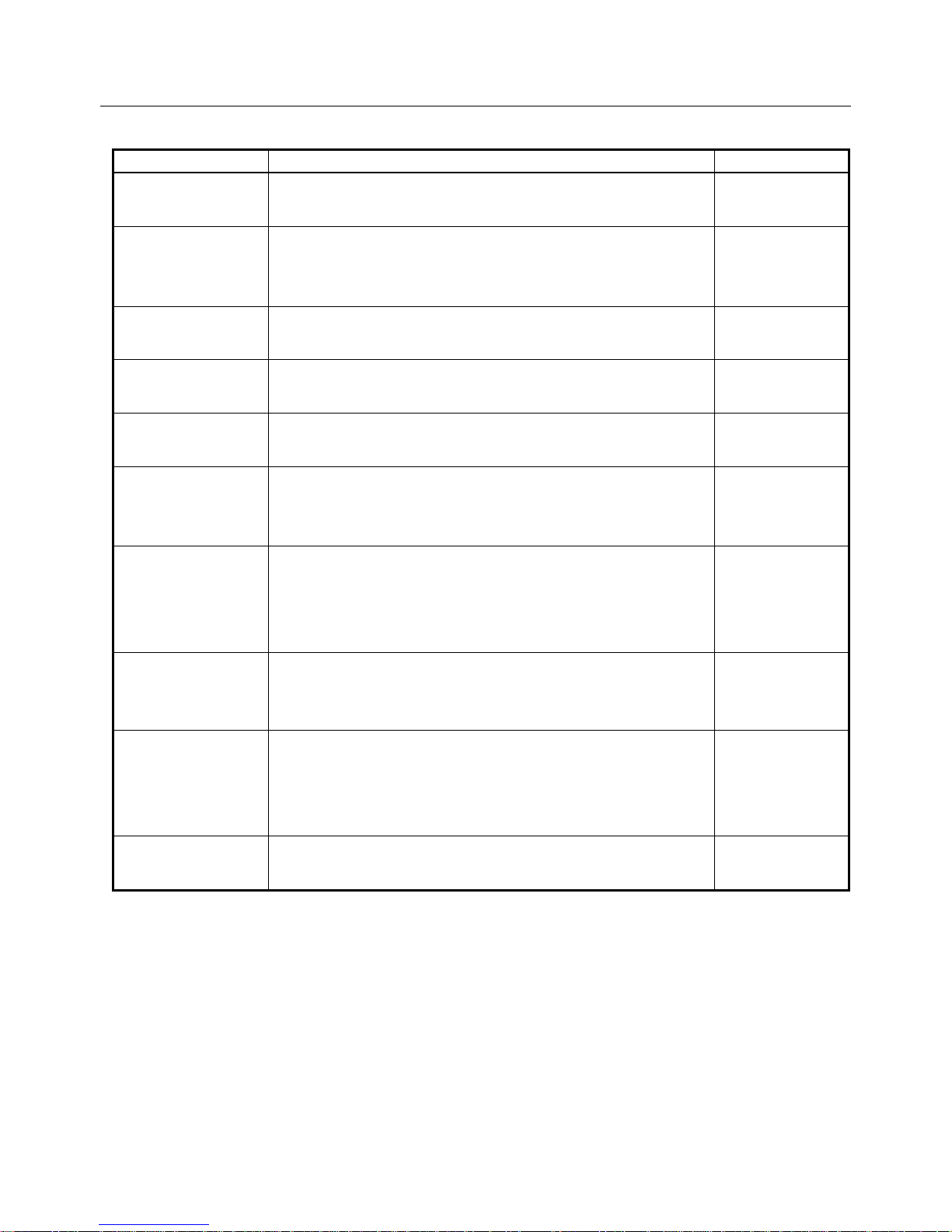
9.Specification
Items
Value
Remarks
Product
360 degree Omnidirection Camera
( Model : NM33D-F )
Power
Voltage: 5.00 V ± 5%
( Absolute Maximum Rated Voltage::-0.3 ~ 6 V)
Maximum Current Consumption : 500 mA
Dimensions
Size : 122.5(W) x 122.5(D) x 93.7(H) [mm]
Weight : 400 g
Operation
Environment
Temperature : 5 ~ 35℃
Humidity : 45 ~ 85% (RH)
No condense
Storage
Environment
Temperature : -20 ~ 60℃
Humidity : 5 ~ 80% (RH)
Lens
Distance to Subject:
10mm(lens surface) ~ infinity
View Angle: 180° x 360°
Image Sensor
Effective Pixel: H:2048 x V:1536(approx. 3.15 Mega
pixels)
Usable Pixel: approx. 1.70 Mega pixels
Minimum Light Required: 5 lux
1/2” single
CMOS
RGB Color
Video Output
( Analog )
Image Signal: COMPOSITE VIDEO 1Vp-p
Output Drive Capacity: 75 Ω
NTSC
Video Output
( Digital )
Signal method: USB1.1(Full Speed mode)
Image Signal : JPEG
Movie Size: 640 x 480、320 x 240 [Pixel]
Maximum Frame Rate: 15 fps
VGA/QVGA
Control Signal
Input
USB1.1
Page 16
Page 16
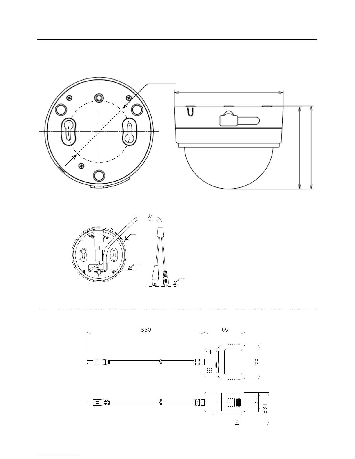
10.Appearance
φ122.5
92.7 93.7
φ70
( Camera )
( AC Adaptor )
[Unit:mm]
A
B
C
※ Length of BNC/DC Cable
Whole length (A - C) : 430 mm
Exposed length (B - C) : 350 mm
《 view with Bottom Cover off 》
 Loading...