

Optal Clear 4070, Clear 4070 RS, Clear 4070 LS, Clear 4070 TS, Clear 4090H Installation & Operation Manual
...
ORTAL Heating Solutions Ltd.
INSTALLATION & OPERATION MANUAL
The ORTAL direct vent (and ORTAL power vent with separate manual) gas appliances have
been tested and approved by CSA for safety and efficiency for use with either Natural Gas (NG)
or Propane (LPG).
Standard references:
ANSI Z21.88-2009 - Vented Gas Fireplace Heaters
CLASS 2901 84 – DOMESTIC HEATERS (GAS) Vented Fireplace – Certified to US Standard
CLASS 2901 04 – DOMESTIC HEATERS (GAS) Vented Fireplace
Pictured Above: ORTAL’s Clear 110 TS
1

ORTAL HEATING SOLUTIONS FIREPLACE MANUAL
TABLE OF CONTENTS
1. Introduction to Ortal and Company Profile 4
2. Fireplace Safety Informat ion and Warnings 5
3. Product Listing 7
a. Certifications and Codes 7, cover
b. Product List: Models and Burners 8
4. Fireplace Clearances 9
a. Standard clearances 9
b. Mantel detail 10
c. Shelf detail 22
d. Stand Alone mounting detail 25
e. Cold Wall Technology 34
f. TV above fireplace install detail 37
g. Double glass air intake detail 43
h. Wall support sample detail 46
5. Gas Information 47
a. Gas type 47
b. Routing of Gas Line 47
c. Gas Pressure and Power Output 48
d. Gas Control Assemblies & Components 55
e. Gas Conversion 57
f. Burner 57
g. Orifices Table 58
h. Pilot & Thermocouple Maintenance 59
6. Install Vent System (also see Appendix A) 60
a. Restrictors & Vent Arrangement 60
b. Schematic Drawing 62
c. Restrictor table per burners 63
d. Vent Installation 68
e. Vent Clearances 68
2

f. Vent Maintenance 68
g. Vent termination 69
7. Fireplace Installation Instructions and Checklist 70
a. Locating Your Gas Fire Place 71
b. Handling the Glass (also see Appendix C) 72
c. Interior Design Media 74
d. Interior Reflective Panel 75
e. Insulation for Cold Climate 76
8. Operating Instructions and Warnings 77
a. Mertik Electronics Control System (also see Appendix B) 77
9. General Maintenance Instru c tion 78
a. General Maintenance 78
b. Ortal Factory Recommended Service 80
c. Service Log 82
10. Manufacturer and Supplier Contact Information 83
11. Sample Product Certification Labels 84
12. List of Appendices 89
Appendix A – M&G DuraVent, Direct Vent Pro with vent termination
Appendix B – Mertik Maxitrol
i. Installation Instructions
ii. Mertik Maxitrol Operating Instructions
iii. Mertik Maxitrol Wall Switch
iv. Mertik Maxitrol Smart Home Connections
v. Mertik Maxitrol Troubleshooting
Appendix C – 500° RTV High Heat Silicon Sealant
Appendix D – Double burner units, special notes
Appendix E – ORTAL USA Trouble Shooting Guide
NOTE: Diagrams and illustrations are not to scale.
3

INTRODUCTION
Company Profile
Welcome to ORTAL and ORTAL USA.
ORTAL, providing heating solutions for over 25 years, is well known for its wide
selection of modern gas fireplaces, produced with close attention to detail, finishing,
heating efficienc y and qual ity. ORTAL’s products combine traditional and modern
design with the technology innovation that ensures a green product with high efficiency
ratings. Our advanced technology produces eye catching fires that are safe, beautiful and
economical. Our product sophistication allows installation in more locations inside the
home.
ORTAL offers the largest selection of modern gas fireplaces in North America available
in an array of sizes to suit design and architectural needs integrating heat into the
aesthetics of life. ORTAL also welcomes clients’ visions for custom-made fireplaces for
special requirements, sizes and uses. Our high quality fireplaces are CSA and CE
certified. ORTAL fireplaces are available in North American through ORTAL USA
approved dealers who each have a strong commitment to offer the best installation and
service.
Green Statement: ORTAL offers a green, environmentally friendly heating
solution for the modern era. With ORTAL’s high efficiency ratings and
contemporary designs, you don’t have to sacrifice form for function. The
unique design maximizes the fireplace’s radiant heat. Additional efficient
components include ORTAL’s use of direct vent technology, electronic ignition (instead
of a standing pilot) and low maintenance requirements.
We appreciate you choosing ORTAL for your fireplace needs.
Thank you,
Ortal and Ortal USA
4

WARNING
Do not store or use gasoline or other flammable vapors and liquids in the vicinity of this
SAVE THESE INSTRUCTIONS
OWNER: Keep this manual for future reference.
FIREPLACE SAFETY INFORMATION
and WARNINGS
:
The direct vent system appliance must be installed as an OEM installation in manufactured
homes (USA only) or an aftermarket permanently located, or a mobile home, where not
prohibited by local codes and must be installed in accordance with
Manufacturer's instructions and the Manufactured Home Construction and Safety Standard,
Title 24 CFR, Part 3280, in the United States, or the Standard for Installation in Mobile Homes,
CAN/CSA Z240 MH Series, in Canada.
If the information in these instructions is not followed exactly a fire or explosion may result
causing property damage, personal injury or death.
appliance.
Make yourself fully aware of all the following instructions and the many features of the
Ortal direct vent gas fireplace appliance.
INSTALLER: Leave this manual with the appliance.
5
WARNING
WARNING
70, or the Canadian Electric Code, CSA C22.1.
WARNING
WARNING
The glass must ONLY be removed by an authorized &/or qualified installer. The
authorized technician should ONLY remove the glass with the glass vacuum holders
supplied by the manufacturer. Lower the glass to rest in a safe place. This is to prevent
damage to the glass edges.
Step 1. Prepare a safe place for the glass to rest.
Step 2. Remove the glass using the vacuum holder.
Step 3. The glass can now be rested safely.
: Glass Handling
: Electrical Grounding
These Direct Vent appliances must be electrically grounded in accordance with the
local codes or, in the absence of local codes, with National Electric code, ANSI/NFPA
: Gas Appliance
This appliance is only for use with the type of gas indicated on the rating plate. These
appliances are not convertible for use with other gases, unless a certified kit is used
and the conversion is performed by an authorized qualified technician.
Applicable standards are Vented Gas fireplace heaters ANSI Z21.88 / CSA 2.33a and
gas-fired appliances for use at high altitudes CAN/CGA 2.17-M91.
: Installation and Service
Installation and service must be performed by an authorized qualified installer service agency or
gas supplier.
Any alteration to the product that causes soot or carbon to form and results in damage is not the
MODELS
responsibility of the manufacturer.
In the case of models supplied with a door fitted in the frame of the heater, ONLY an
All the models referenced in this manual are equipped with the same basic equipment
authorized qualified installer may open this door. The end user must NOT open the door, as this
including: firebox and leg supports, burner, gas valve, glass panels, operation control,
may be unsafe and may result in voiding the manufacturer’s warranty.
special tools, etc.
ALL the warnings and instructions apply to ALL the models.
6

PRODUCT LISTING
Certifications and Codes
The appliance has been certified for use with either natural gas (NG) or propane gas (LP), and
NOT for use with solid fuels.
These gas fireplace appliances are CSA certified and approved for indoor use and can be
specialized with certain requirements for indoor outdoor use (i.e. tunnel models). For indoor
installation they must be installed maintaining required clearances. Installation is recommended
in living spaces such as bedrooms, living rooms, great rooms, etc. The appliance is not approved
for closet insta ll at ion.
The appliance must be installed according to ORTAL and ORTAL USA requirements in addition
to any local codes that may apply. If none exist then the current CSA installation code must be
followed:
• USA, ANSI Z223.1/NFPA 54
• Canada, CSA B149
The appliance must be properly connected to an M&G DuraVent chimney venting system. Refer
to the specific appliance to determine vent size and pathway requirements.
1. Consult the authority having jurisdiction to determine the need for a permit
PRIOR to starting the installation.
2. It is the responsibility of the installer to ensure that this fireplace is installed
in compliance with the manufacturer’s instructions and all the applicable
codes.
3. Before starting, take careful note of ALL the WARNINGS in this manual.
7
Burner
Models
Chimney size
• Clear 40/ RS/LS/TS/ Tunnel,
Small Square, Classic Corner, Modern Corner
Space Creator 120/Mini/Medium
• Clear 150/ RS/LS/TS/Tunnel,
Clear 170/ RS/LS/TS/ Tunnel
• Clear 200, Clear 200RS/LS/TS/Tunnel, Space
Product List: Models and Burners
Burners and venting for models can be seen in the table below. Adaptors are not required.
30
(Series 40)
45
(Series 70 &
80)
100
(Series 110,
120 & 130)
• Stand Alone 40 TS
• Clear 4070/RS/LS/TS/Tunnel
• Clear 4090H/RS/LS/TS/Tunnel
•
• Clear 60x80/ Tunnel
• Clear 75/RS/LS/TS, Stand Alone 75/TS/Hood
• Space Creator 75
• Clear 75H TS, Clear 7565/Tunnel
• Clear 80/RS/LS/TS,
• Clear 8070H/RS/LS/TS
• Classic F 75/80
• 4 Glass Island
• Clear 110, Clear 110 RS/LS/TS/Tunnel
• Stand Alone 110
• Clear 110 H/ Tunnel
• Clear 130/RS/LS/TS/Tunnel/Top
• Island 130
•
4x6
4x6
5x8
135
(Series 150
& 170)
160
(Series 200)
Two
Burners
• Space Creator 150
• Stand Alone 150
•
Creator 200
• Clear 20070H/RS/LS/TS
• Clear 250/RS/LS/TS/Tunnel
• Clear 250/RS/LS/TS/ Tunnel
• Clear 350/ RS/LS/TS/ Tunnel
• Clear 400/ RS/LS/TS/ Tunnel
• 4 Glass 2 burners
Refer to Appendix E for specific information relating to
these Two Burner models.
5x8
5x8
5x8
8

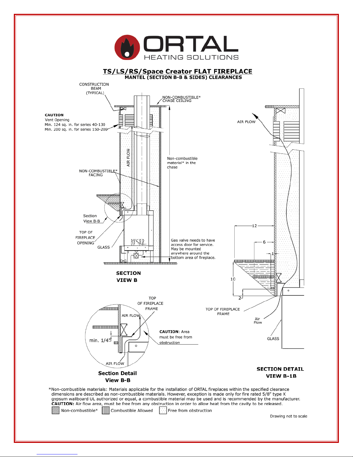
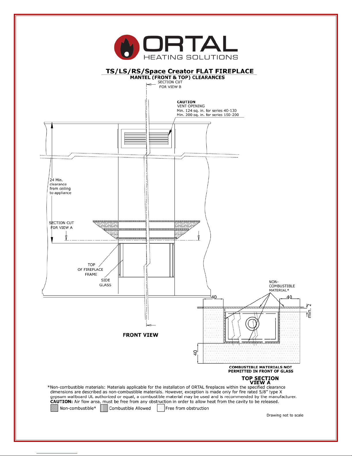
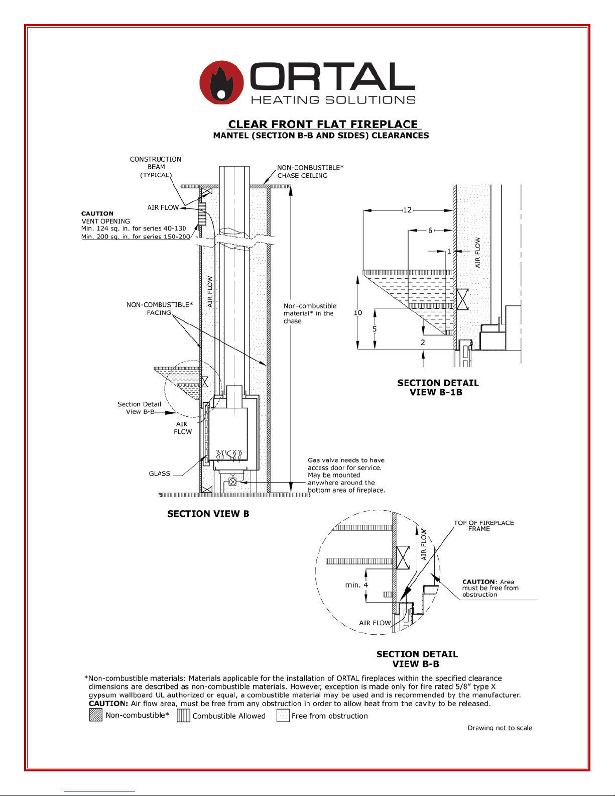
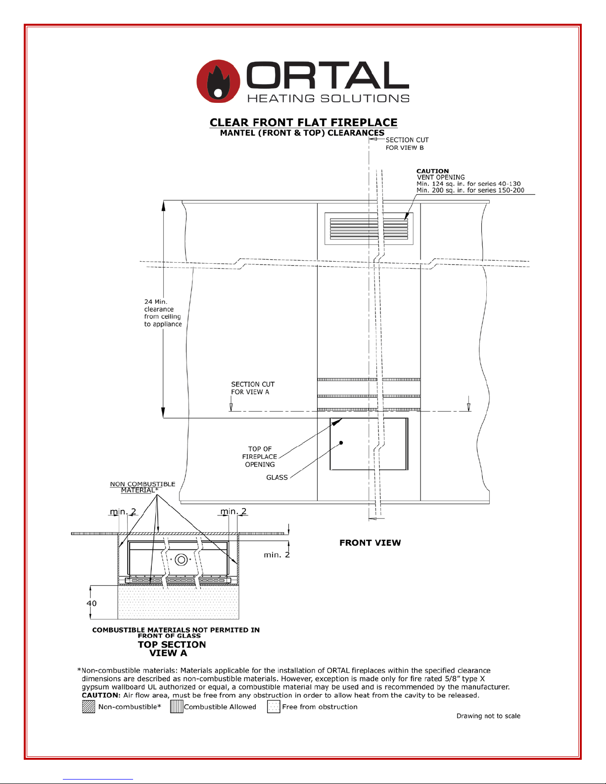
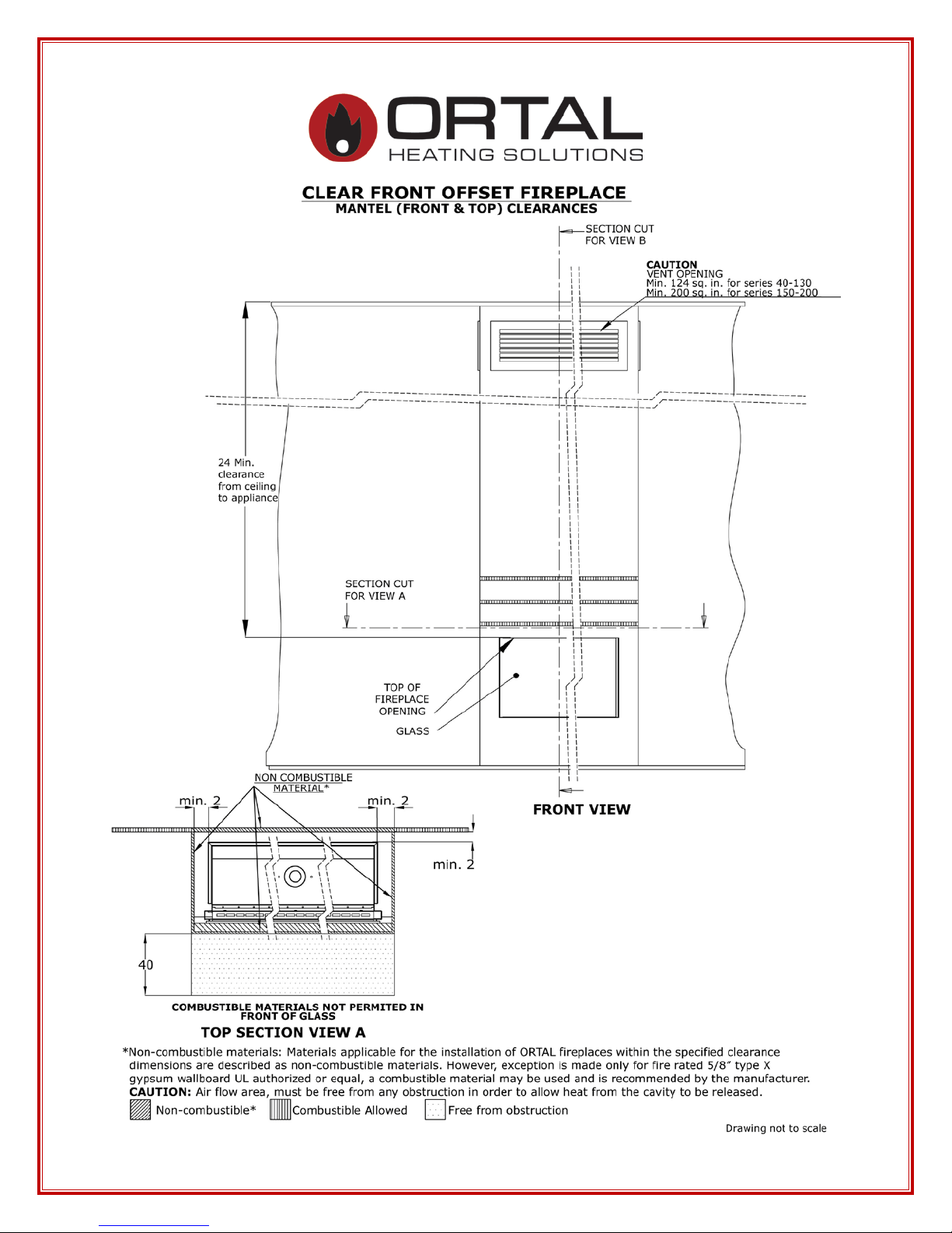
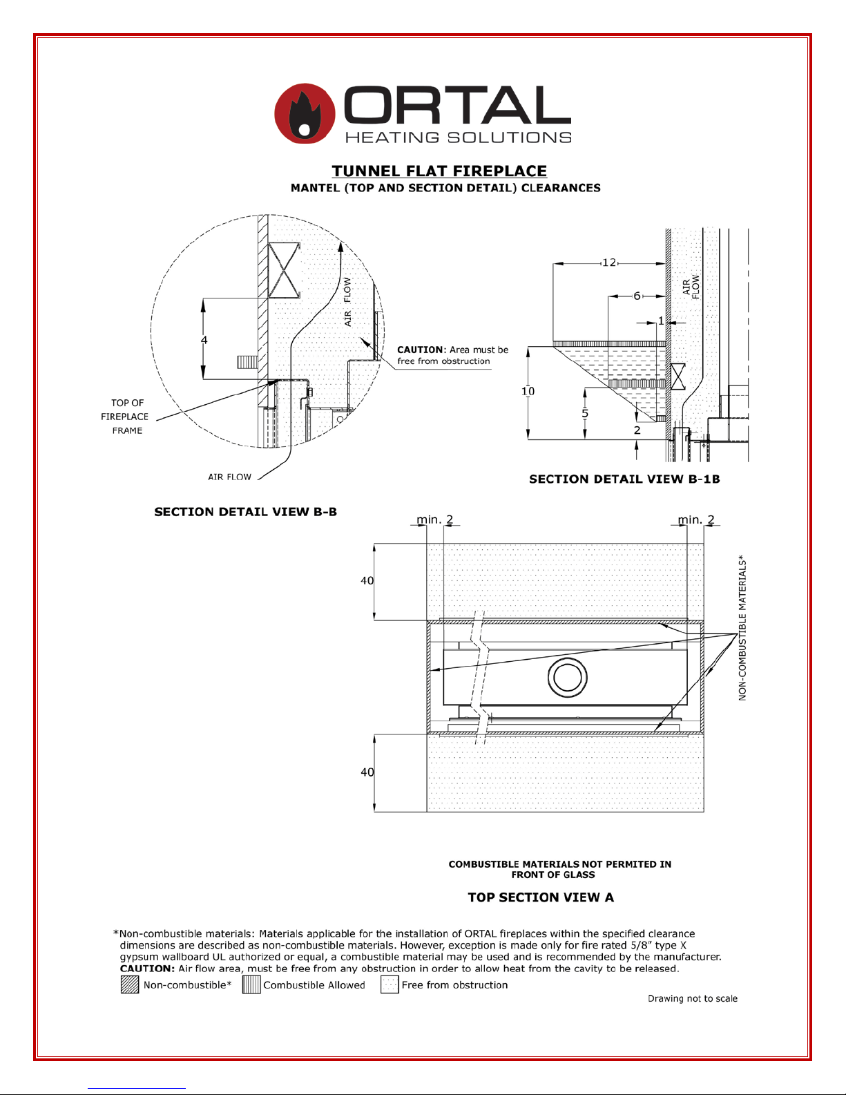
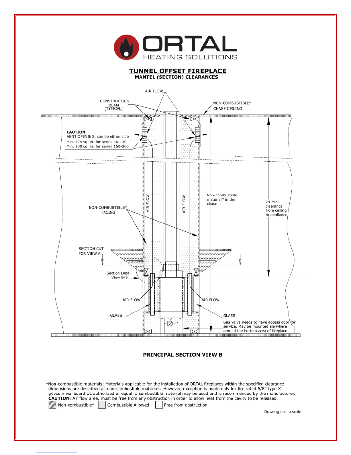
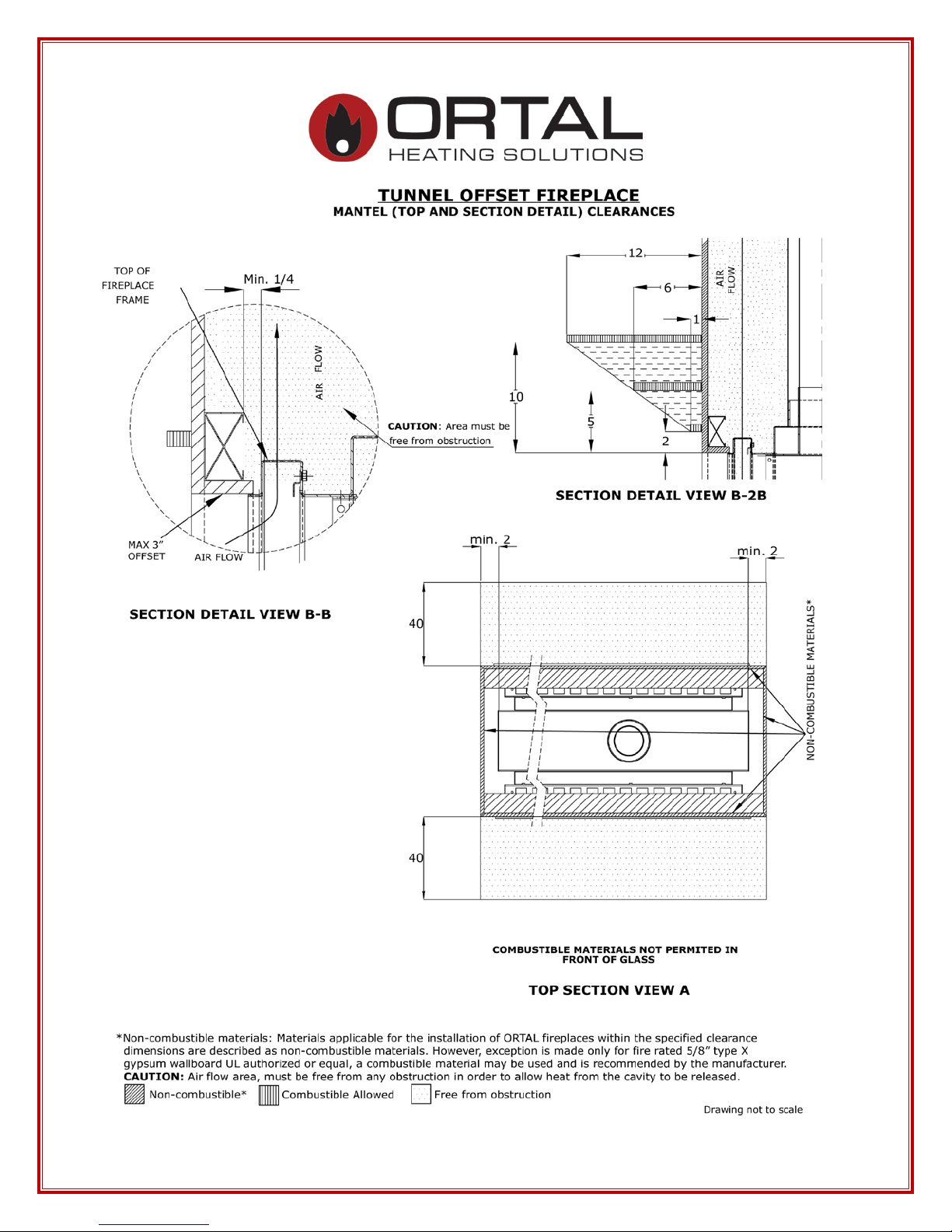
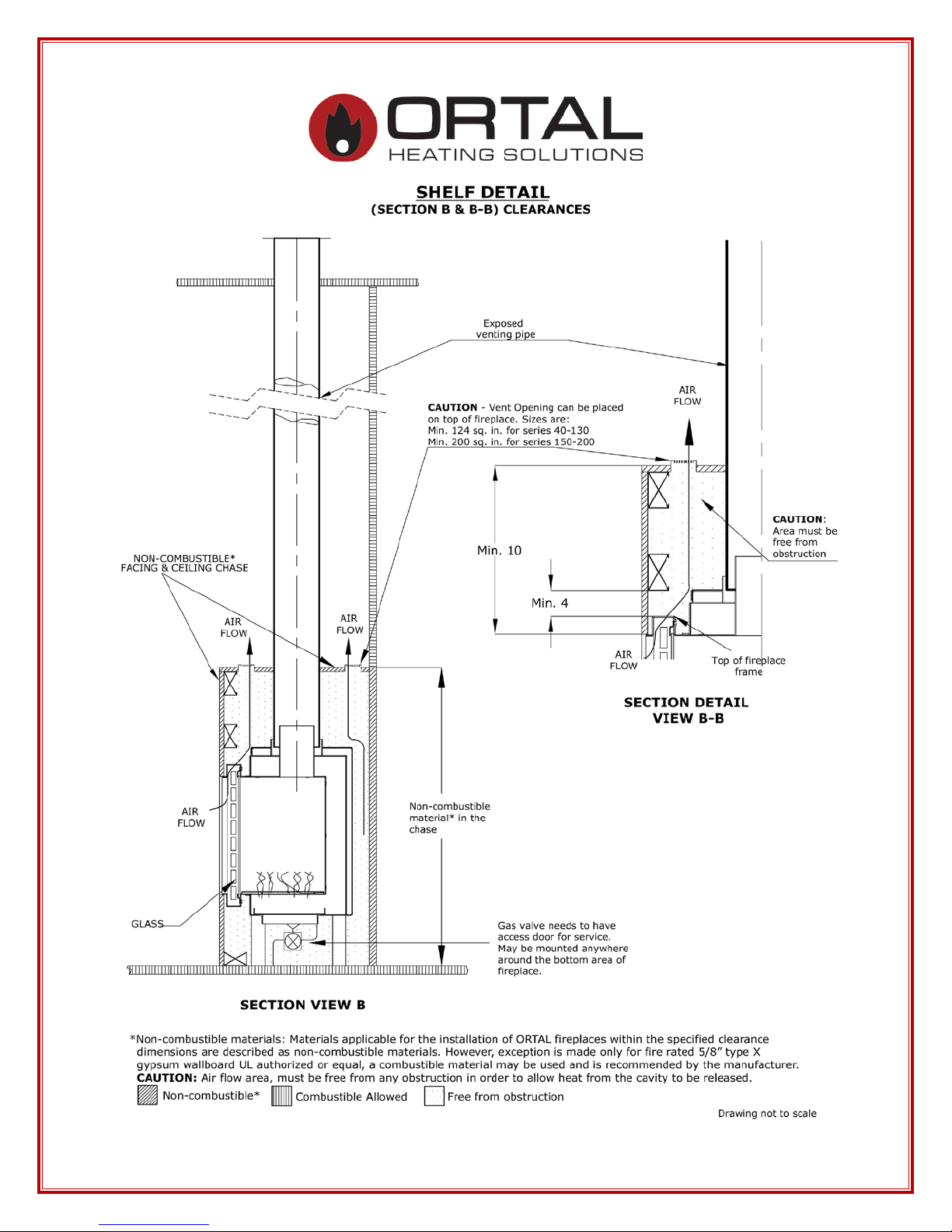
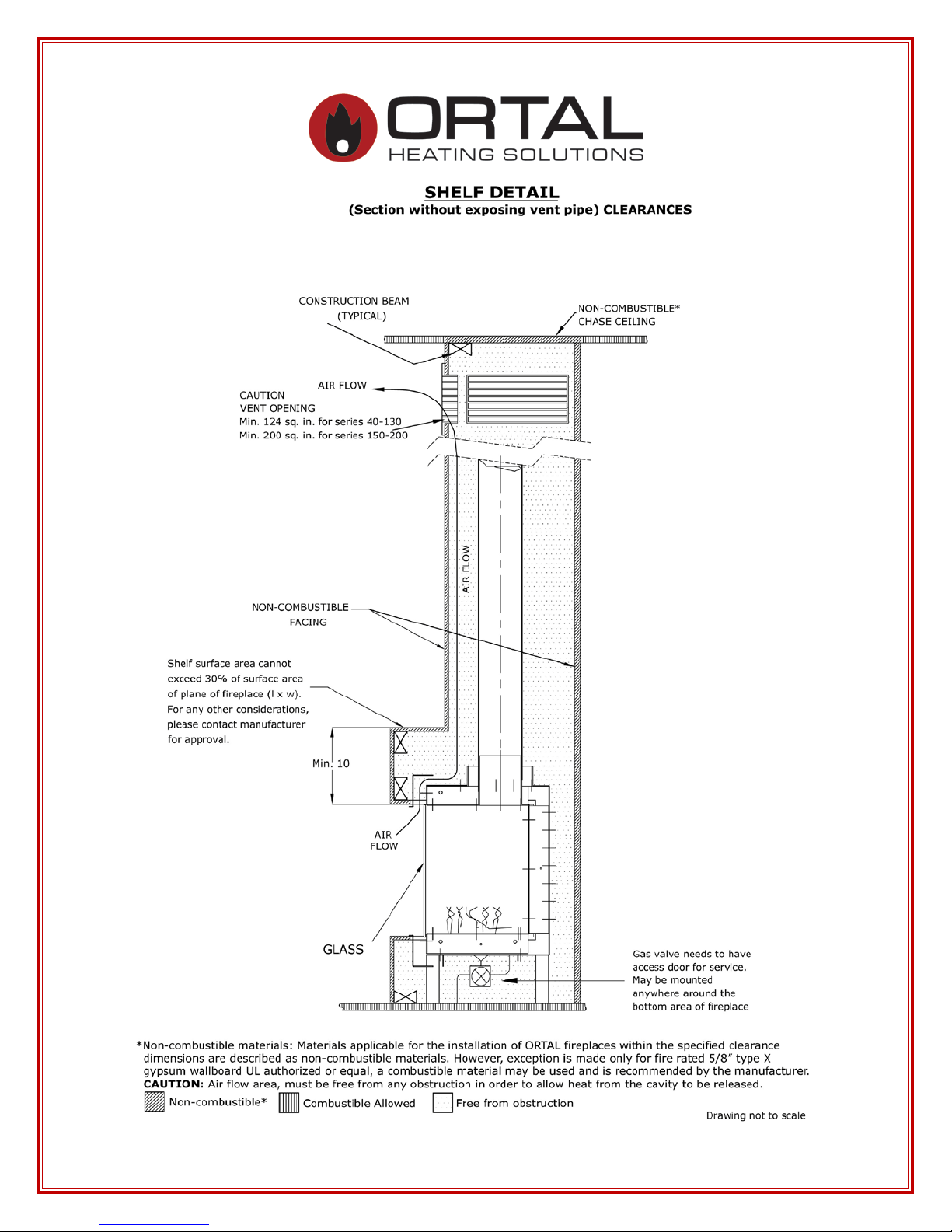
FIREPLACE CLEARANCES
Minimum Clearances to Combustible Materials
Appliance and Vent Clearances
The appliance is approved with maintained minimum clearance to combustible materials
as shown in the diagrams provided.
Non-combustible materials, such as surrounds and other appliance trim, may be installed
on the appliance face so long as it maintains the minimum clearances between the
appliance and the non-combustible material. Surrounding material is not allowed to
transfer weight to the unit or be connected in any way to the unit. They must not cover
any portion of the removable glass panel or the control compartment.
The minimum clearances (air space) to combustible materials must be adhered to. It is of
the greatest importance that the fireplace and vent system be installed only in accordance
with these instructions.
Clearance Diagrams on f ollowing p ages.
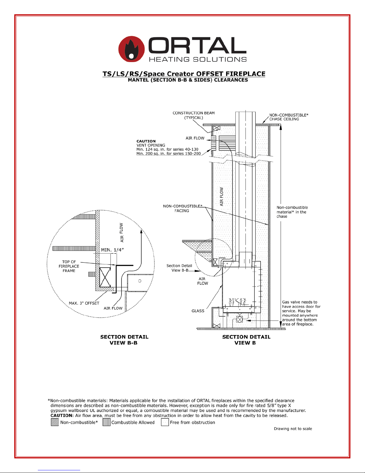
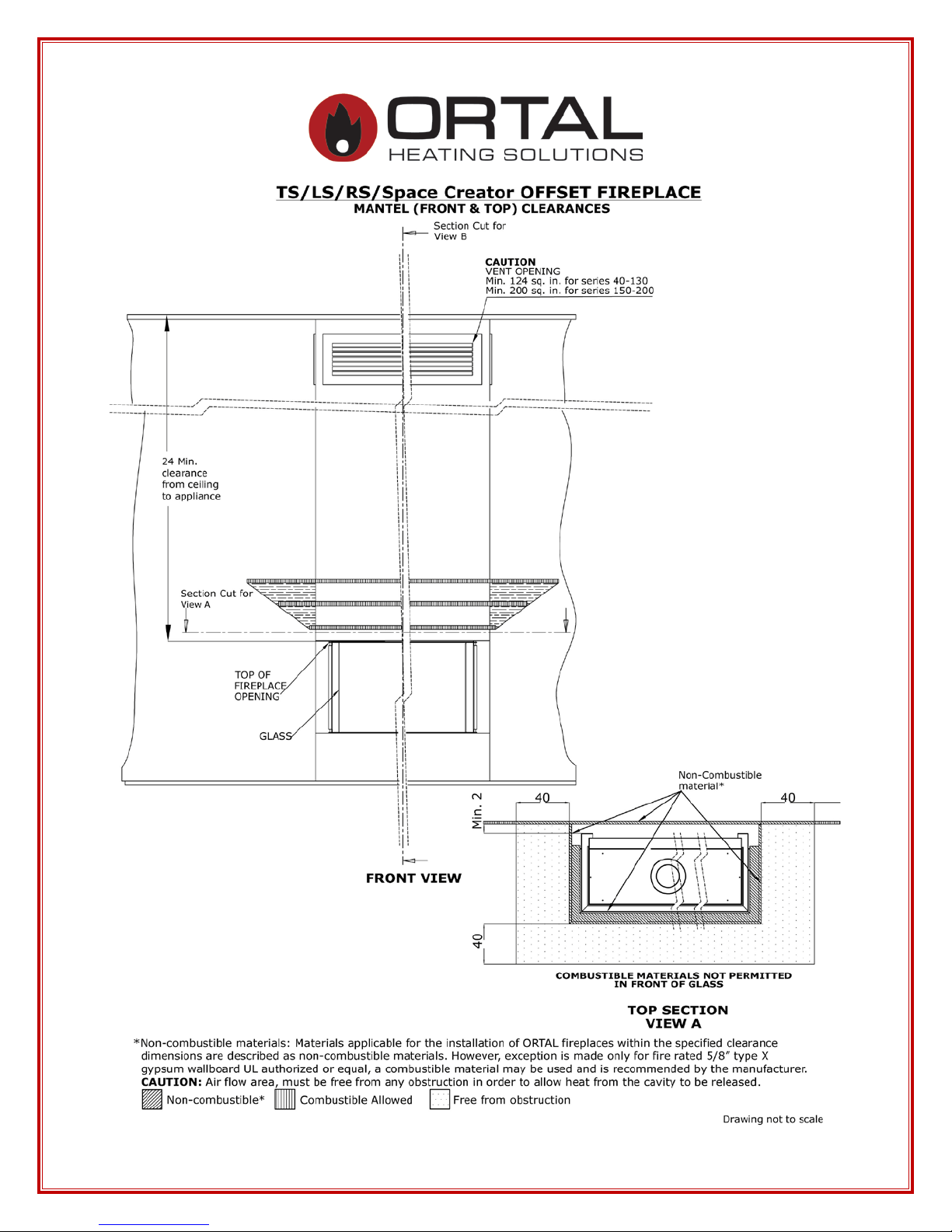
Definitions:
“Flat”: walls surrounding finish in the same plane as the fireplace.
“Offset”: walls surrounding finish in a different plane as the fireplace and there is 90
degree (usually) between the plan of the fireplace and the plane of the wall. Maximum
3” horizontal space between the two planes.
9
10
11
12
13
14
15

16
17

18
19
20
21
22

23
24
Stand Alone 40 TS, 75, 75 TS, 110 & 150
Manufacturer’s Recommendation for Wall Mounting
1. Concrete Wall
a. Position the unit at the desired height and mark the wall. Unit should have
a minimum 12” and maximum 30” distance from the bottom of the unit to
the floor.
b. Mount the Stand Alone hanging bracket using Hilti 3/8” x 3” Kwik bolt 3
expansion anchors with manufacturer’s requirement of 2-1/2” embedment
and torque to 20ft-lbs.
c. Attach the unit to the mounting bracket.
d. See Sketch 1 for detail.
2. Wood Stud Wall
a. Position the unit at the desired height and mark the wall. Unit should have
a minimum 12” and maximum 30” distance from the bottom of the unit to
the floor
b. Create an opening in the wall big enough to position the 4x8 blocks
between the wood studs at the desired height.
c. Repair the opening with hardy backer board.
d. Make sure that the bracket has a minimum 4” extra hardy backer board
material around it.
e. Mount bracket with a 3/8” x 4” lag bolts. Follow bracket manufacturer’s
installation requirements and then mount the unit.
f. See sketch 2 for detail.
Note: All installations are to be completed per local building codes and safety
requirements. The above recommendation does not take the place of reviewing and
incorporating structural requirements set forth by the building engineer, local codes, etc.
25
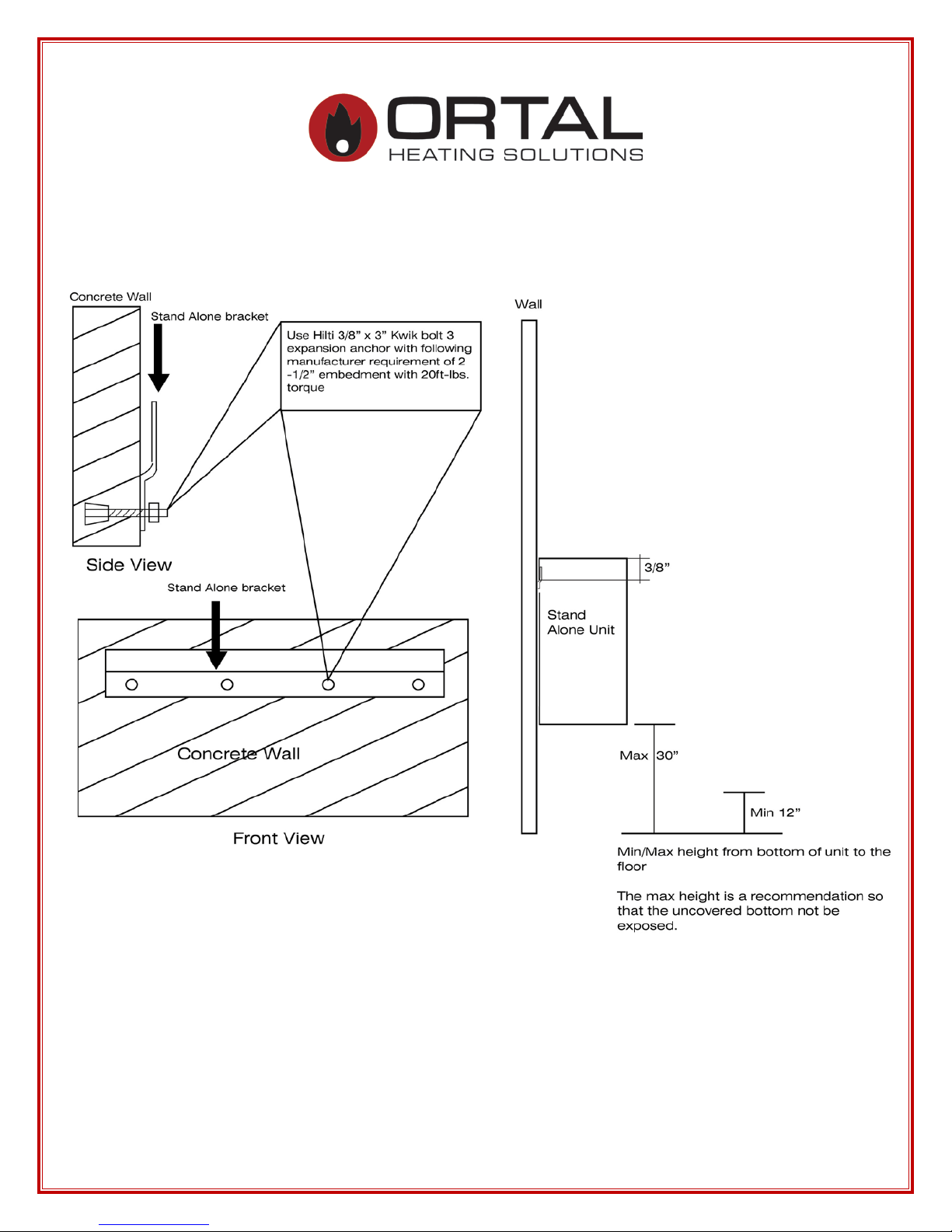
Concrete Wall Mounting Detail
Sketch 1
26
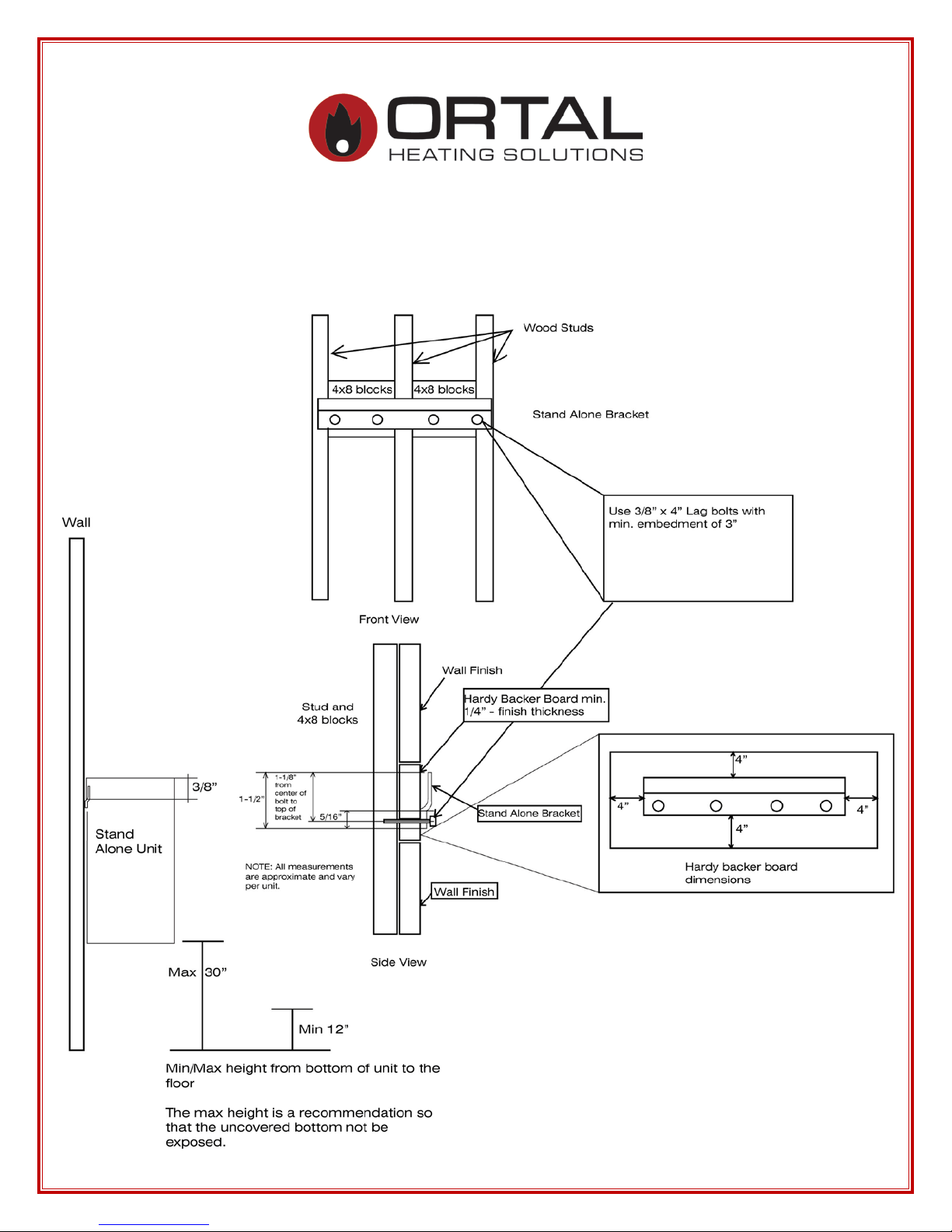
Wood Stud Mounting Detail
Sketch 2
27
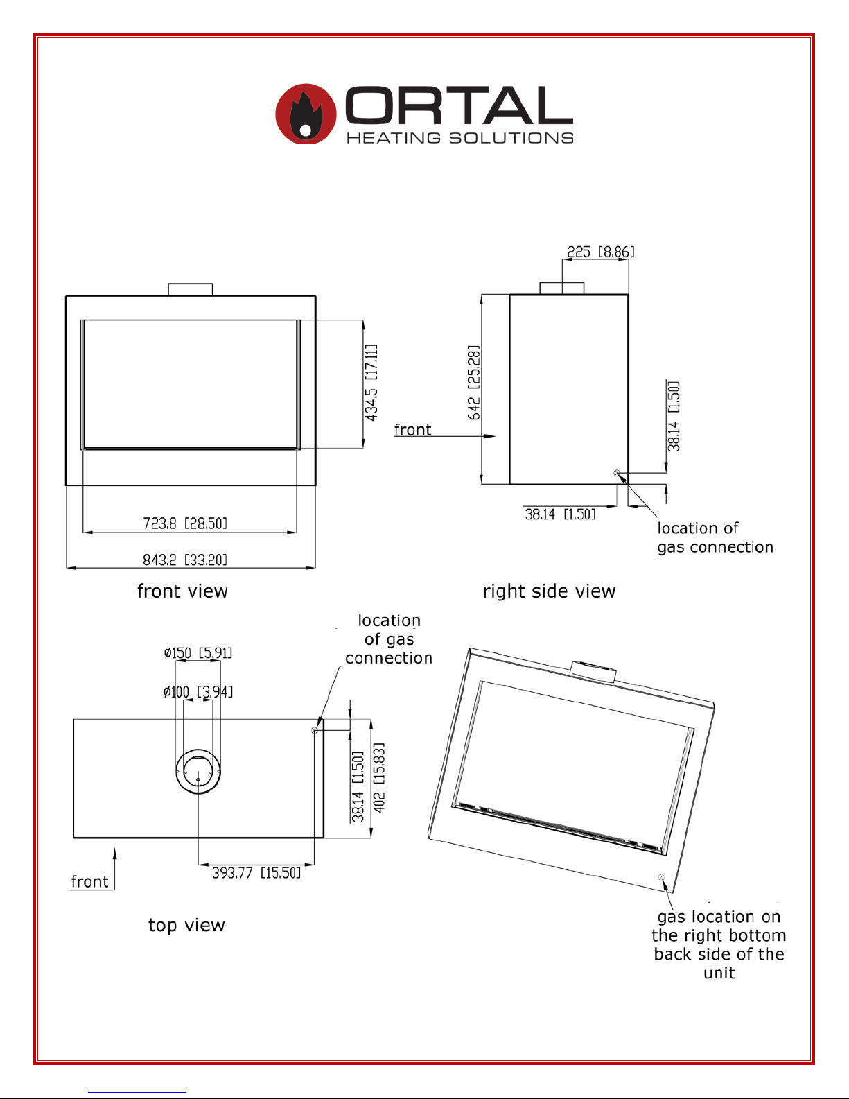
Stand Alone 75
28
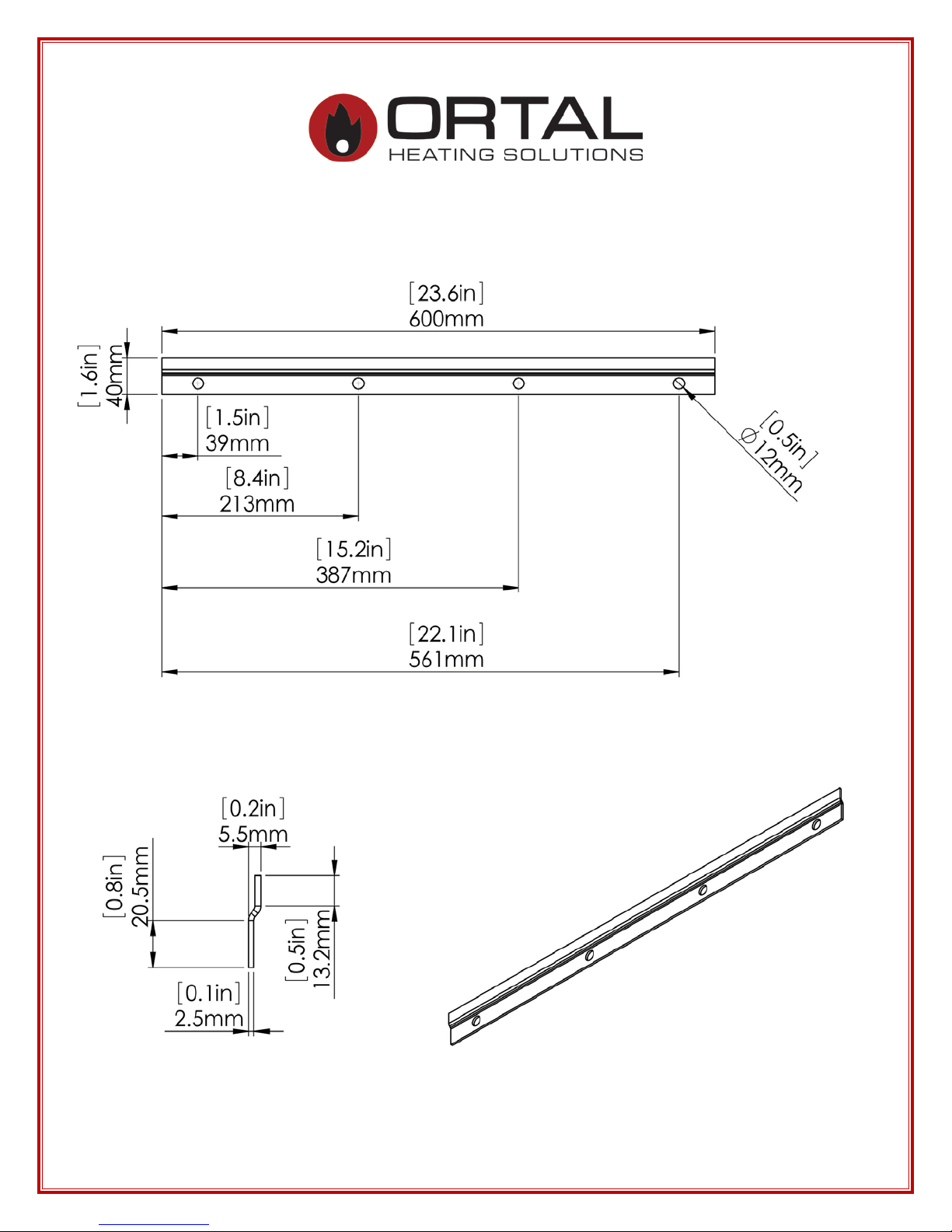
Stand Alone 75 bracket
29
Stand Alone 110
30
 Loading...