

Page 1
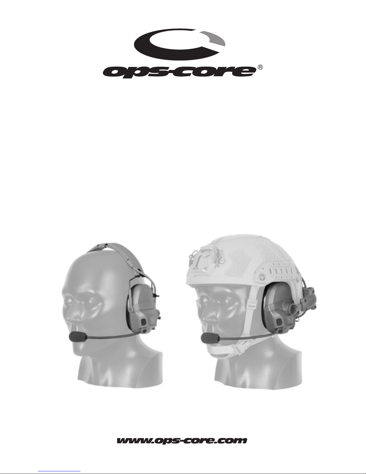
AMP™
(Adaptive Mission Platform)
Communication Headset
CONNECTORIZED VERSION
Operator’s Manual
OM101153-00
This product is covered by one or more patents.
For more information visit www.gentexcorp.com/patents
Page 2

Page 3

TABLE OF CONTENTS
Introduction
Product Highlights / Key Features
Product Overview
Preparing the AMP Communication Headset for Use
Installing/Replacing Batteries
Moving Microphone to Opposite Earcup
3D Hear-Through (3DHT) Mode
Near Field Magnetic Induction (NFMI) Earplugs
Helmet Rail Mounted Operation
Hook and Loop Fastener Installation
Headband Removal
Rail Arm Installation
3
4
6
8
8
9
12
14
16
17
18
20
Helmet Attachment
Stowed Position
Helmet Donning / Dofng
Detaching Rail Arms
Removing Earcups from Rail Arms
Attaching Earcups to Headband
Attaching Headset Downlead
Maintenance
Storage
Troubleshooting
Customer Service
22
24
26
28
30
32
34
36
37
38
39
Specications
Operator Notes
40
42
Page 4

2
Page 5
INTRODUCTION
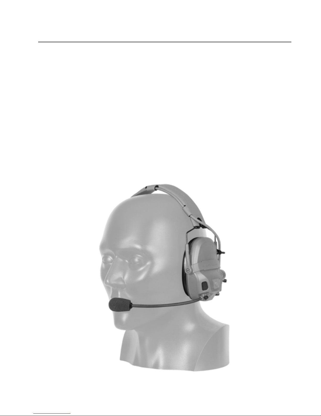
About the Ops-Core AMP (Adaptive Mission
Platform) Communication Headset
The advanced hear-through and hearing protection capabilities in the Ops-Core
AMP Communication Headset enhance situational awareness and user safety. For
optimal exibility and performance, the modular headset can be easily congured
to meet a wide range of mission needs with options for headband or helmet
mounted use, single or double hearing protection (NFMI models only), and single
or multi-channel communications.
3
Page 6

PRODUCT HIGHLIGHTS / KEY FEATURES
• World Class Audio Quality
Leveraging industry leading capabilities of the military, industrial safety hearing
protection, and communication systems of parent company Gentex Corporation, the
Ops-Core AMP Communication Headset provides unprecedented audio quality with
ability to operate in combat environments.
• 3D Hear-Through (3DHT)
Restores and enhances “natural hearing” of outside environment for improved
situational awareness. Ear-simulator design reproduces ambient sounds with a high
degree of directional accuracy, while also providing robust hearing protection.
• Optional NFMI (Near Field Magnetic Induction) Earplugs (sold separately)
Provide increased noise reduction, while maintaining clear communications and 3D
Hear-Through. NFMI Earplugs do not require wires or batteries. NOTE: Compatible
with NFMI headsets only.
• Mission Congurable Capability
Dual conguration capability adapts headset to either headband or helmet mounted
preference based on operational requirements.
• Ergonomic Headband
Engineered for optimal comfort and streamlined prole, capable
of being worn under a helmet. Quick attach/detach from headband capability.
• Rail Mount Kit (sold separately)
Optional rail arms can be mounted to rear of ARC rails, leaving top portion
of rails free for other accessories, while increasing helmet stabilization and
a counterbalancing effect of shroud mounted devices. Single point gimbal
attachment to earcups allows for 360˚ adjustment, providing a better earseal and
accommodation of head movement. Rotate earcups to side or rear of helmet to
create low prole, streamlined stowage when not in use.
4
Page 7

• Quick-Release Downlead Connections
Disconnect headset from downlead(s) to allow for set up on left, right or both sides.
System can quickly congure between single, dual, or no downlead.
• Noise Canceling Microphone
Mitigates background noise enabling clear communication. Can be mounted to left or
right earcup or removed as preferred.
• Integrated Microphone Mounting & Connection Point
Enables easy integration with any U-173/U standard plug.
• Earseals
Ergonomically designed to t head geometry, providing better seal and increased
noise attenuation.
• Auto Shut-Down
To preserve battery life, alert tones signal 3DHT shut down after two hours of
inactivity. Pressing volume button resets timer. Included AAA lithium batteries provide
115 hours of 3DHT use.
• Fail-Safe Communications
In the event of battery loss, 3DHT will power off leaving headset and earplugs to
operate for standard communication.
5
Page 8
PRODUCT OVERVIEW
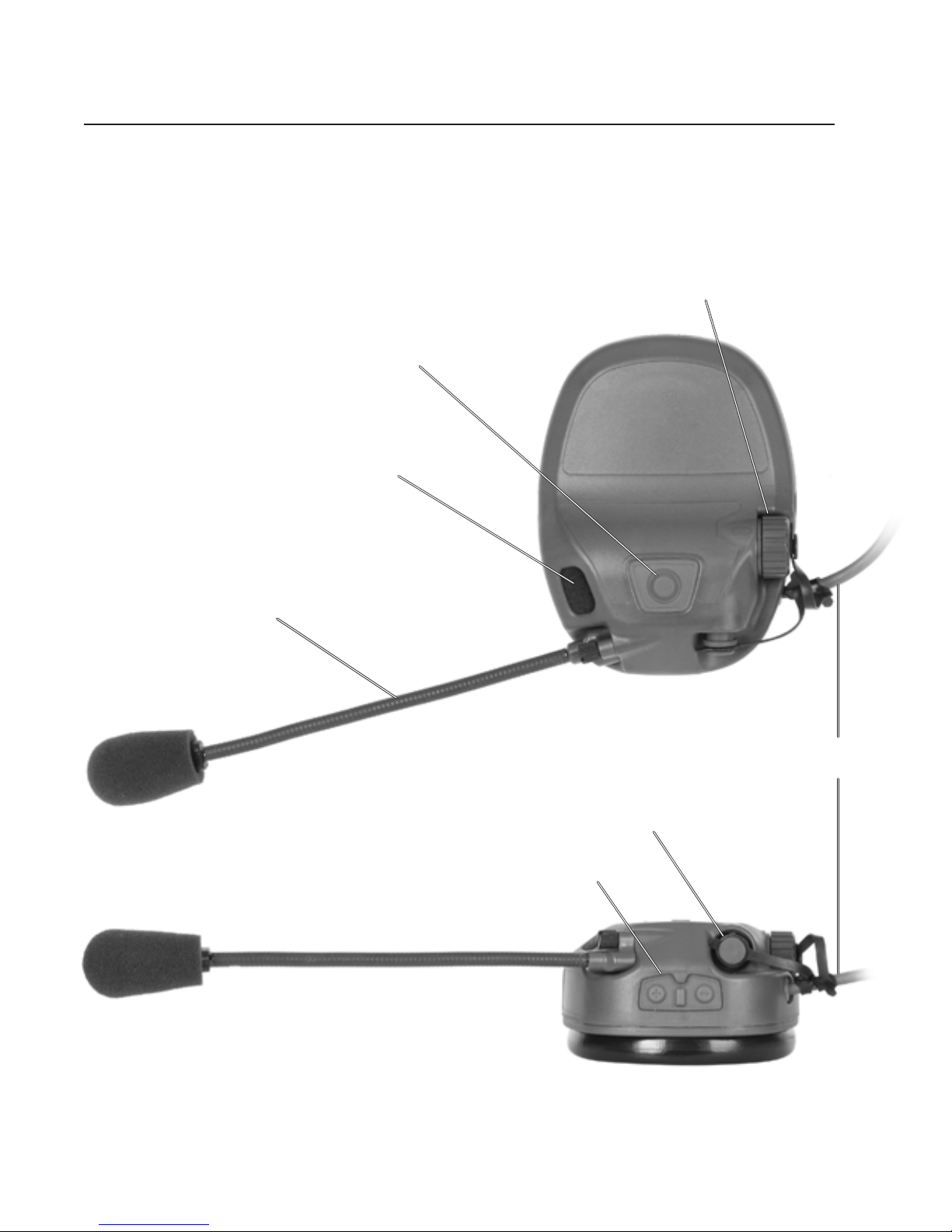
LEFT EARCUP
NFMI Button (NFMI models only)
Hear-Through Microphone
External Battery Cap
Boom Mic Assembly
Ear-to-Ear Cable
Downlead Connector
Volume Buttons
6
Page 9
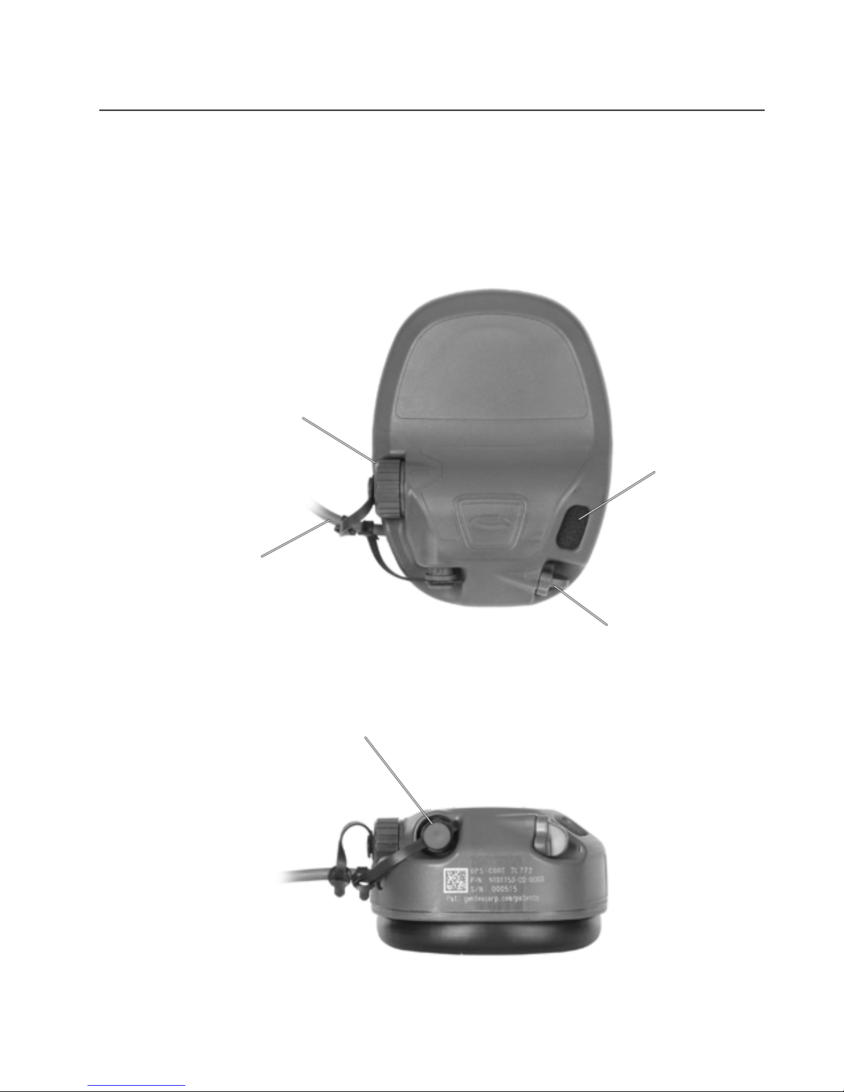
External Battery Cap
Ear-to-Ear Cable
RIGHT EARCUP
Hear-Through
Microphone
Downlead Connector
Mic Port Plug
7
Page 10
PREPARING THE HEADSET FOR USE
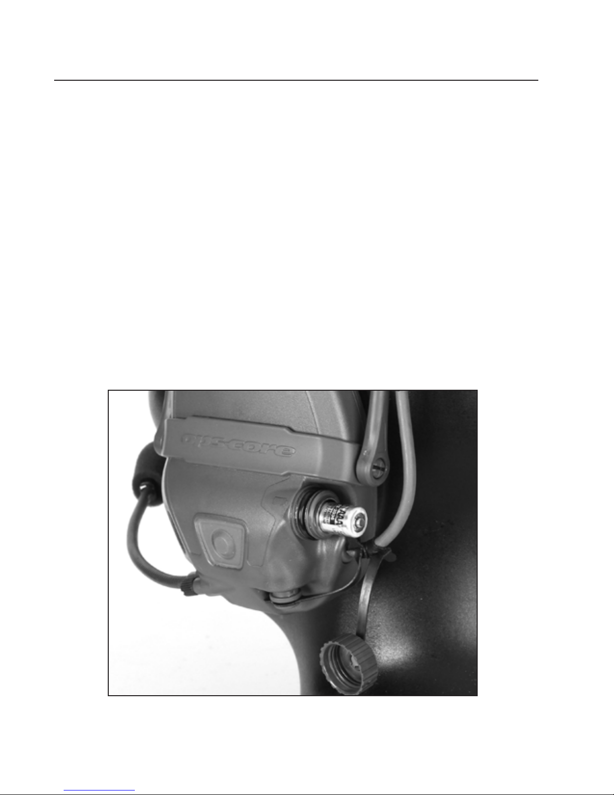
Installing/Replacing Batteries:
1. Unscrew battery tube cap
2. Insert the battery into the battery tube with positive (+) end facing outwards
3. Reinstall battery tube cap and ensure that it is tight
4. Repeat steps on other earcup.
NOTE: For optimal performance, always use lithium batteries and
always replace as a set in both earcups. Remove batteries when
headset is not in use for longer durations.
8
Page 11
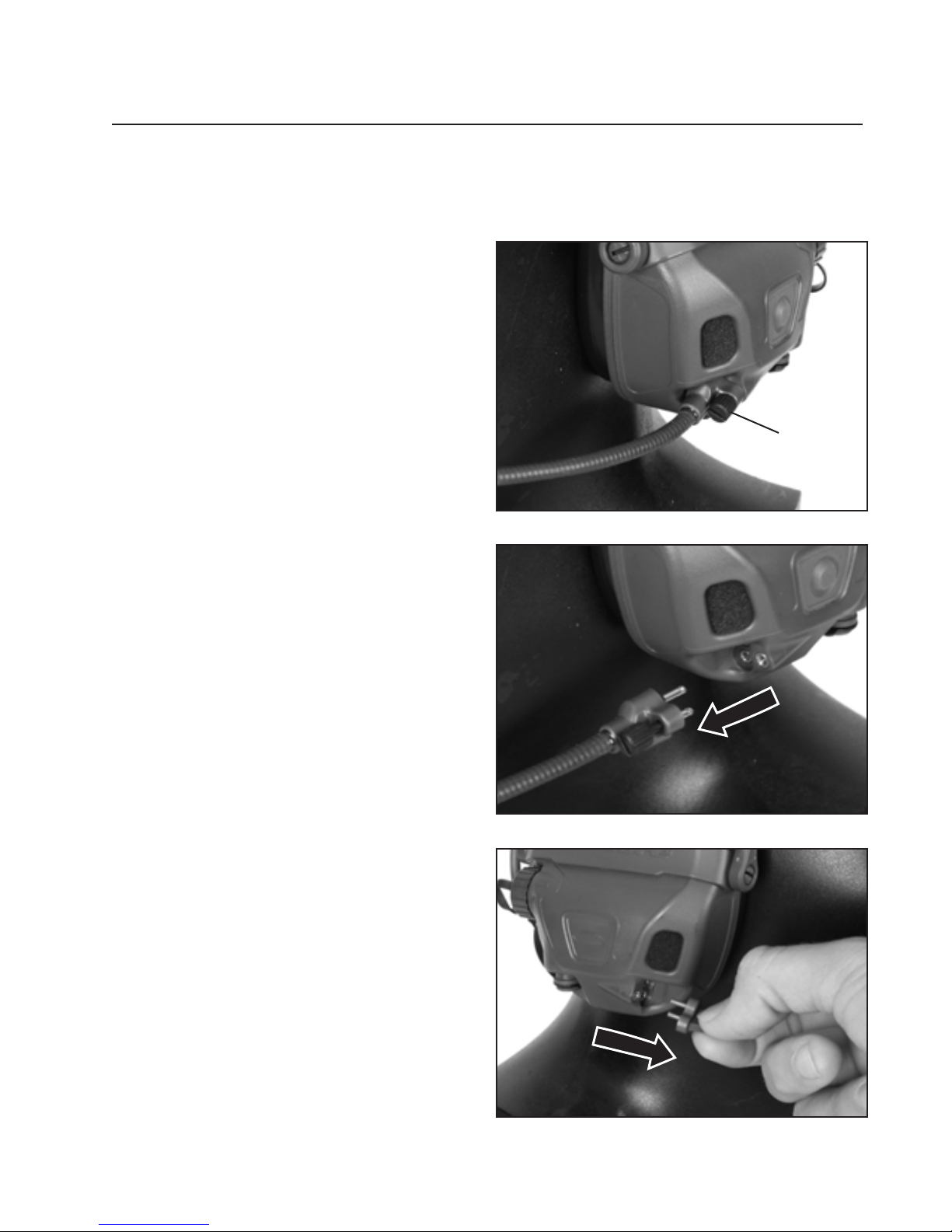
Moving Microphone to Opposite Earcup (Optional):
1. Loosen the thumb screw that
attaches the microphone to
the earcup.
Thumb
Screw
2. Unplug the microphone by
grabbing the ex boom and
pulling it straight away from
the earcup.
3. Remove the mic port plug on
the opposite earcup.
9
Page 12
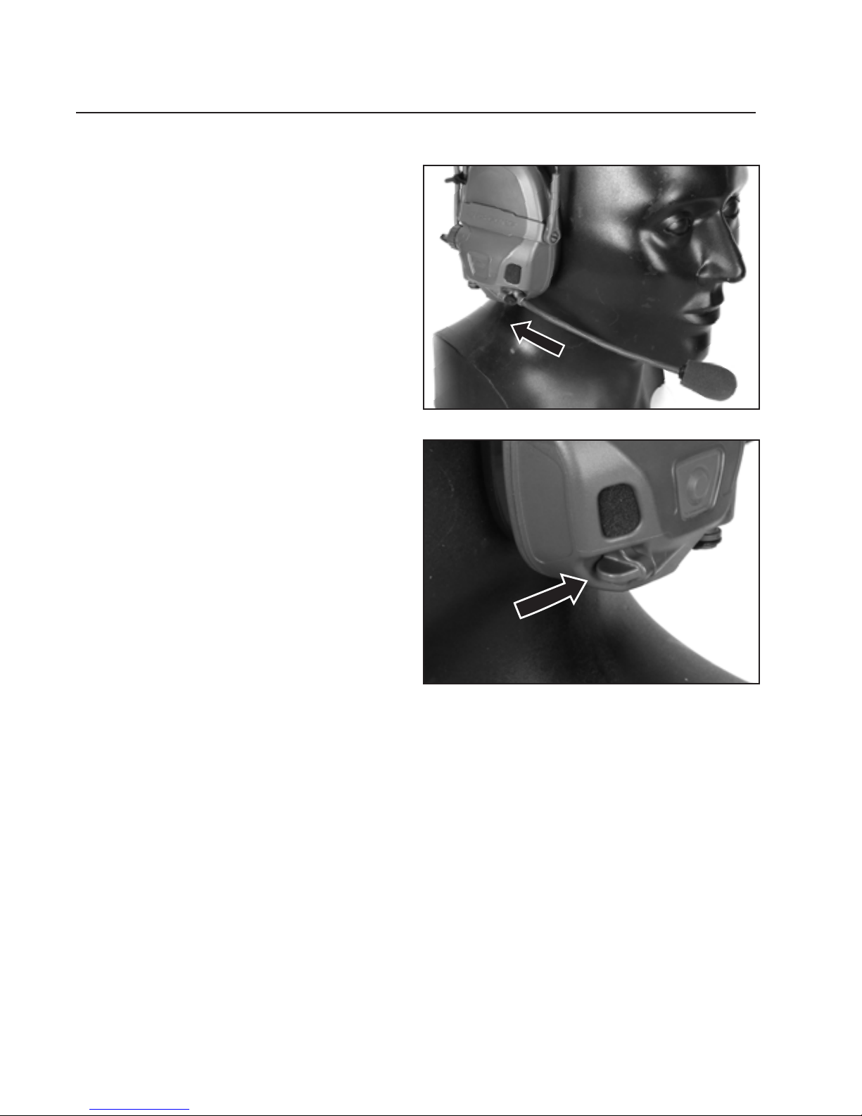
4. Plug the microphone into
the opposite earcup and
tighten the thumbscrew
by hand. If desired, you
may use a athead
driver to tighten 1/8 turn
beyond nger tight (12
inch-ounces).
5. Install the mic port plug
onto the earcup from
which you removed the
microphone.
NOTE: If you desire to
congure the headset
without a boom mic
for listen only / hearthrough only operation,
skip steps 3 and 4.
10
Page 13

11
Page 14

3D HEAR-THROUGH (3DHT) MODE
Operating the 3D Hear-Through (3DHT) Mode
The 3D Hear-Through mode reproduces ambient sounds from the environment
through the earcups for increased situational awareness. The radio / intercom
communications function continues with hear-through turned on or off.
To turn Hear-Through ON: Press and hold any volume button. The headset emits
three ascending tones, and the hear-through function activates.
To increase Hear-Through volume: Press or hold the forward volume + button.
The headset emits a short tone that gets louder as the volume increases.
To decrease Hear-Through volume: Press or hold the rear volume – button.
The headset emits a long tone that gets softer as the volume decreases. At the
lowest volume position, hear-through function will mute.
To turn Hear-Through OFF: Press and hold the volume + and – button together.
The headset emits three descending tones, and the hear-through function ceases.
Hibernation Mode Alerts
If no volume presses in 2 hours, you will get a
Hibernate
hibernation warning every 15 seconds for 1 minute (to
Warning
reset time duration press a volume button).
Hibernation
After 2 hours of hear-through use with no volume
Mode
12
presses, hear through will power off.
Page 15
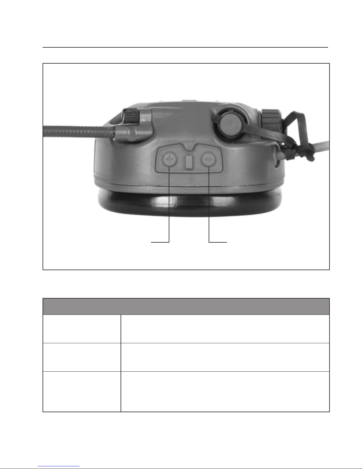
Vol (+)
Vol (-)
Low Battery Warning Alerts (with lithium batteries)
Initial Low
Battery Alert
Very Low
Battery Alert
Shut Down
Button
Button
50 mins (approx.) of remaining use.
Indicated by 4 tones.
20 mins (approx.) of remaining use.
Indicated by 3 groups of 4 tones at higher amplitude.
0 mins of remaining use.
The headset hear-through will power off. Radio
communication will continue to function.
13
Page 16
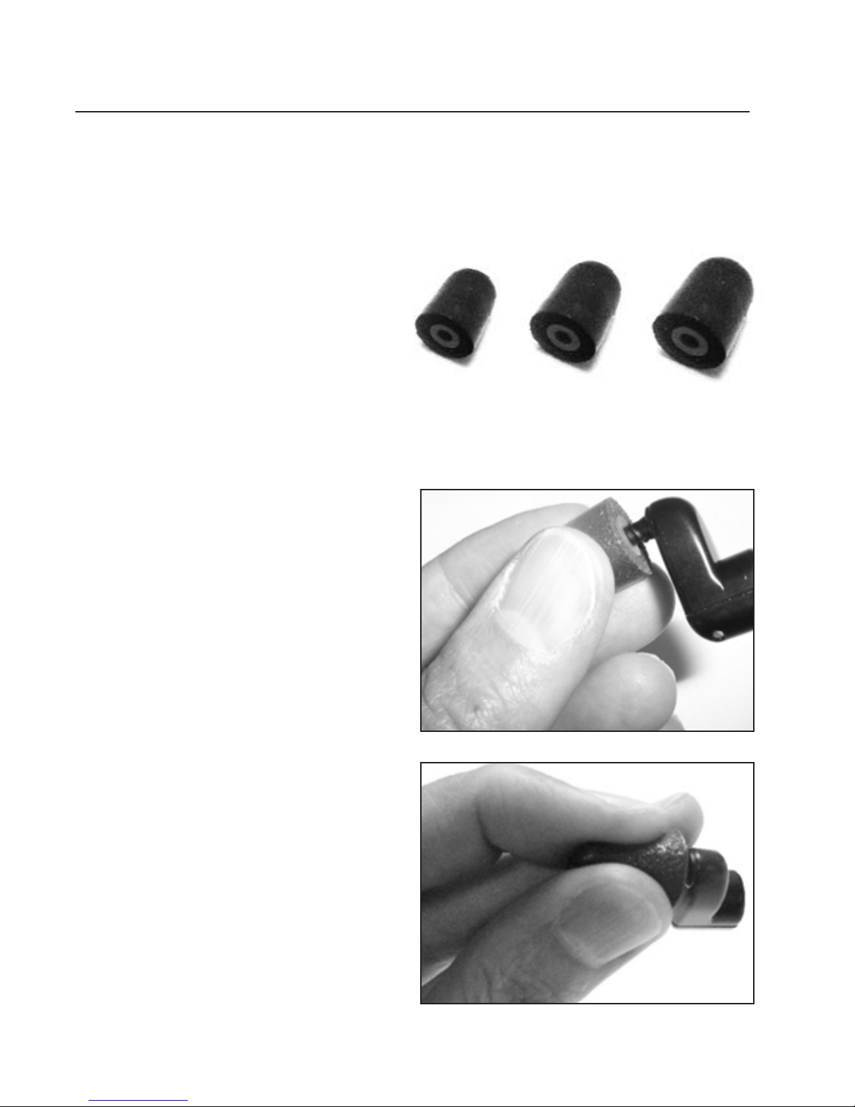
NFMI EARPLUGS
Using NFMI Earplugs (sold separately):
1. Select the standard tips to
start and remove the foam
tips from the packaging. Foam
tip sizes are Slim, Standard,
and Large (in case of tting
problems, try the next smaller
or larger size, as needed).
2. Thread foam tips onto the
earplugs. Ensure that the
foam tip is fully threaded
onto the earplug.
3. Roll the foam tip between
your ngers to compress it.
14
Page 17
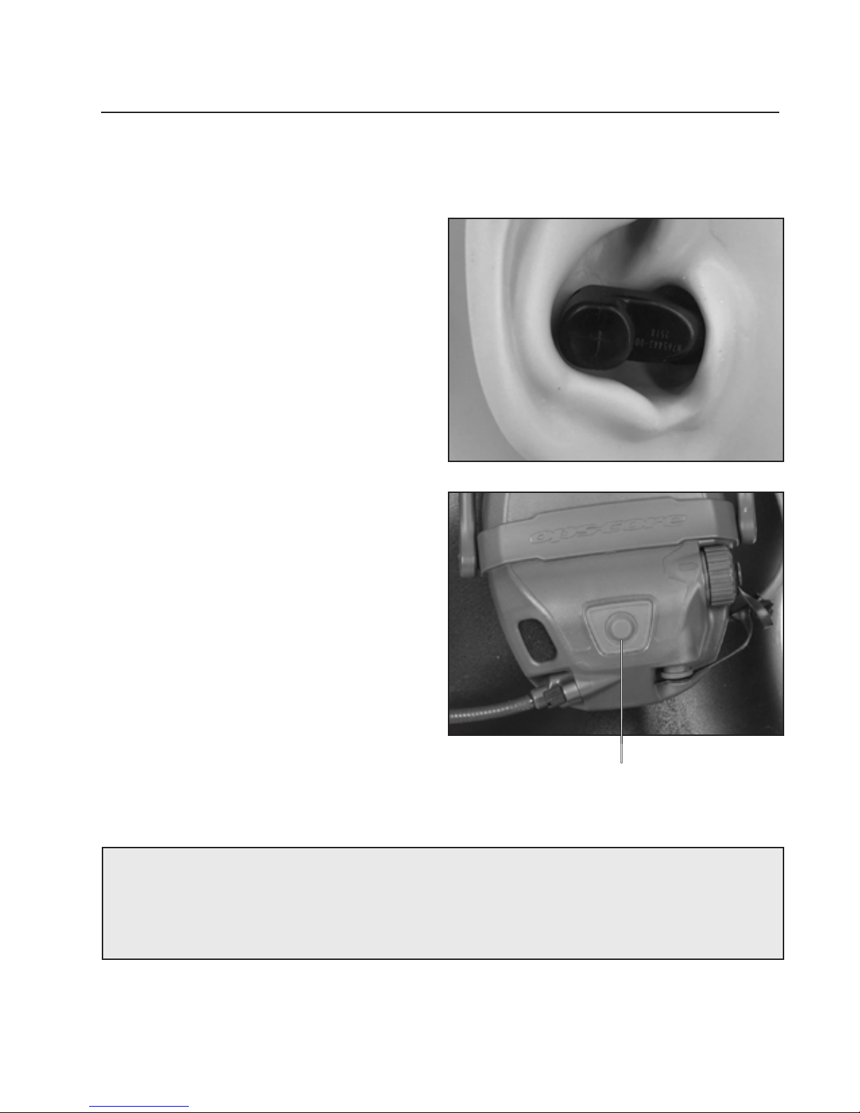
4. Carefully insert the foam tip into
the ear, ensuring the earplug is
level in the ear as shown.
5. Repeat Steps 3 and 4 to insert
the other earplug into other ear.
6. Don headband / helmet; adjust
and connect the headset.
7. Press the NFMI button on the left
earcup to transfer the audio from
the earphone to the NFMI earplug.
A double tone is emitted for
conrmation.
NOTE: If you engage the NFMI button without the earplugs in,
you will receive no audio.
NFMI Button
15
Page 18
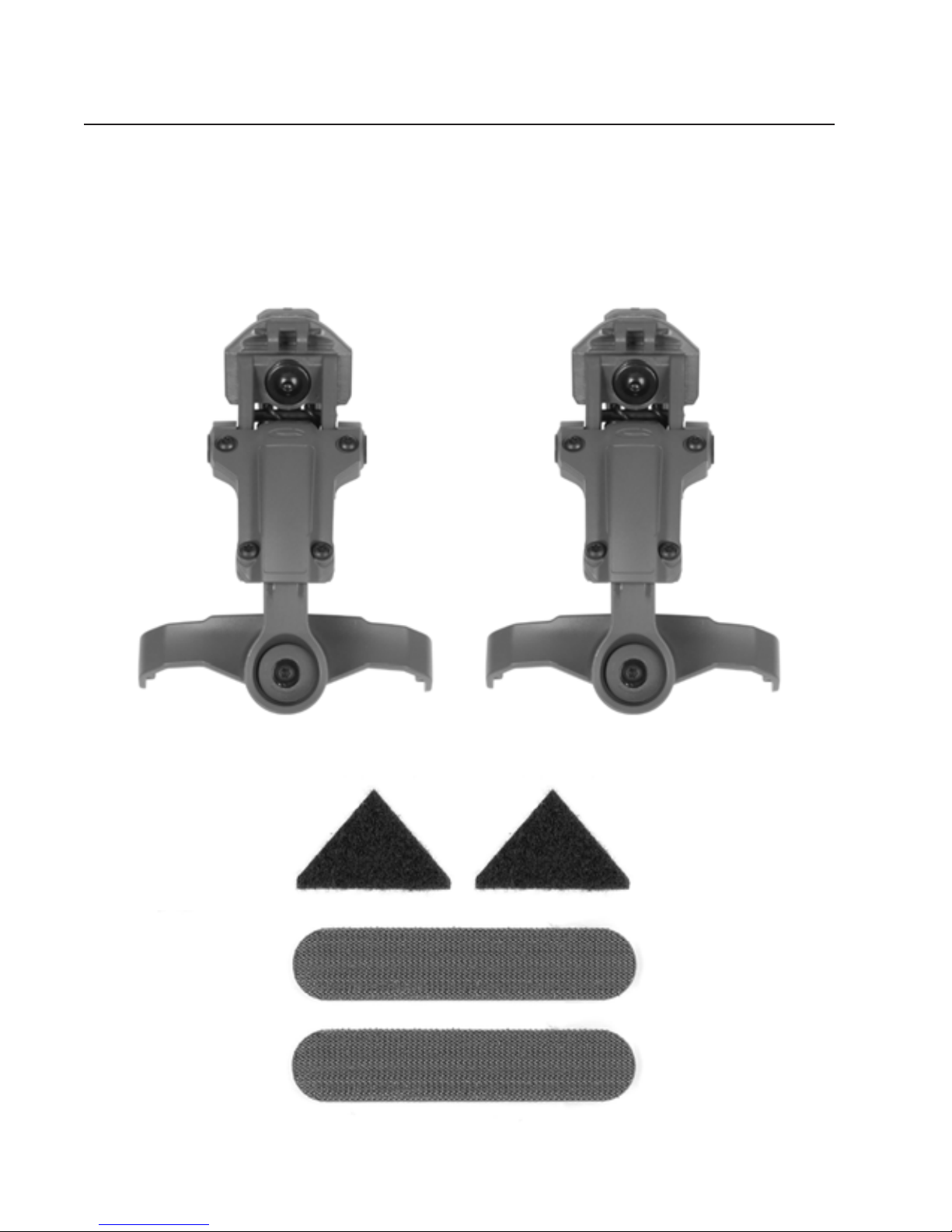
HELMET RAIL MOUNTED OPERATION
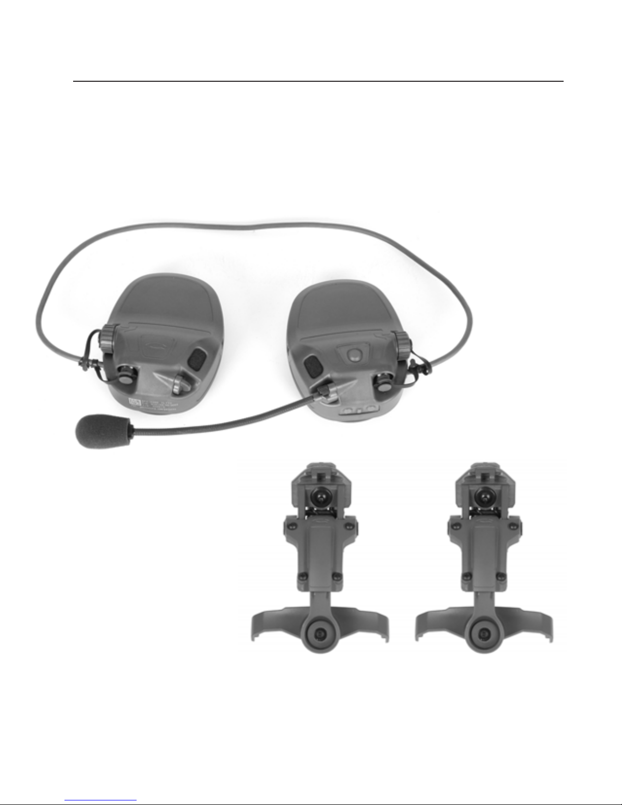
Helmet Rail Mount Kit (sold separately)
Use the following components to mount the headset to the helmet:
Rail Arms (2)
16
Loop Fastener Triangles (2)
Hook Fastener Strips (2)
Page 19
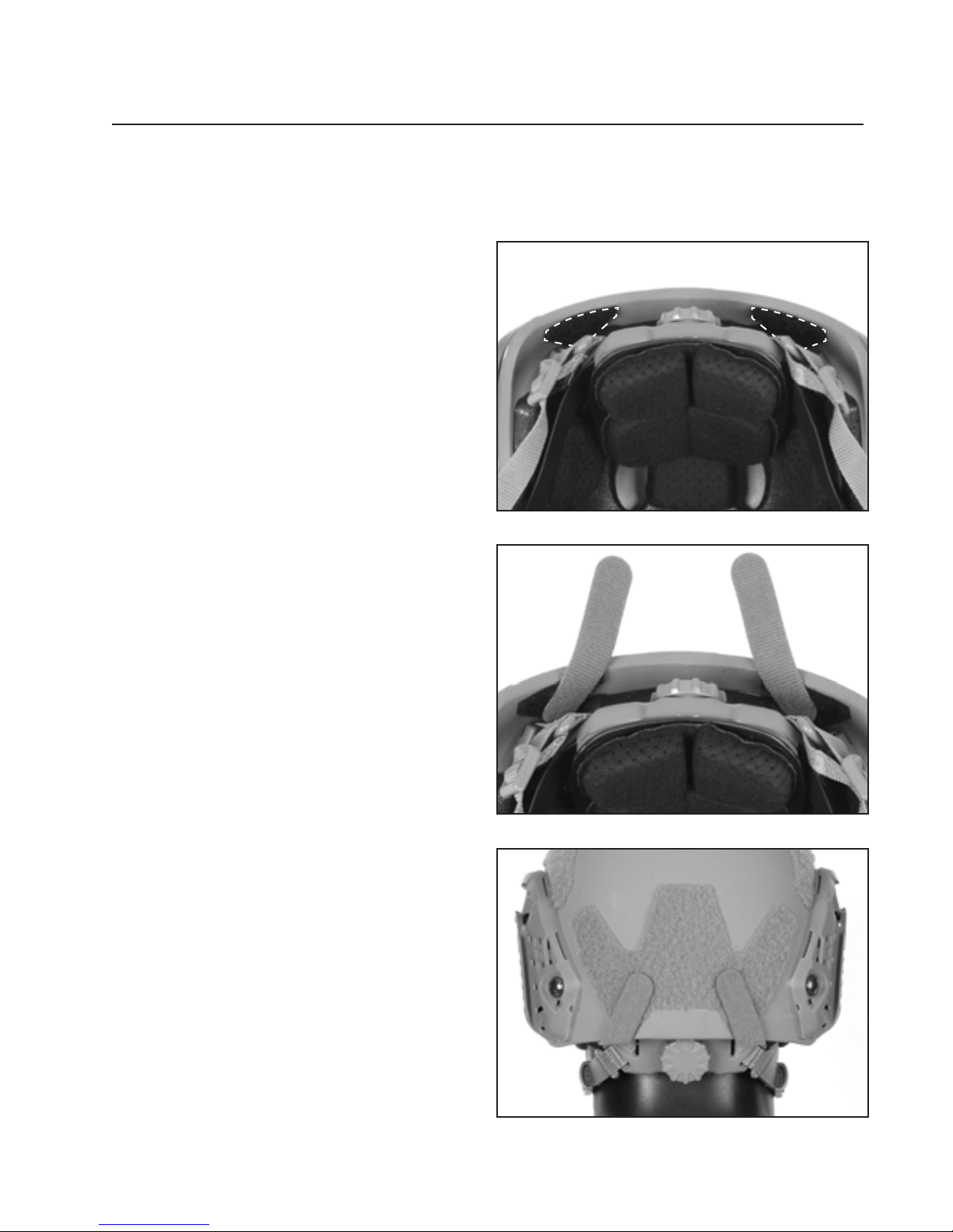
HOOK & LOOP FASTENER INSTALLATION
Install the loop fastener on the helmet:
1. Remove the backer from the
adhesive backed loop fastener
triangles and install inside the
rear lip of helmet as shown.
2. Install the two pieces of hook
fastener strips as shown.
3. Adjust hook fastener strips
position as necessary to properly
route the ear-to-ear cable.
17
Page 20
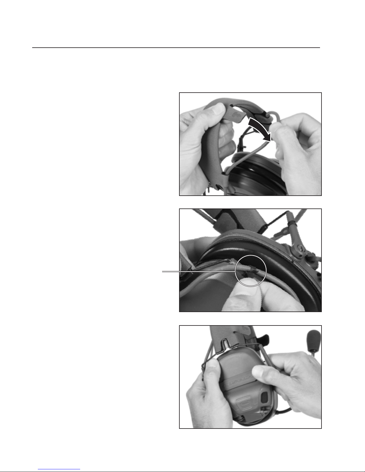
HEADBAND REMOVAL
Removing the Earcups from the Headband:
1. Unfasten the three loop
fastener cable retention
tabs on the headband to
free the ear-to-ear cable.
2. Unfasten cable
management straps
Cable Management Strap
3. Grasp the back of one earcup
with one hand.
With your other hand, place
your thumb on the headband
strap and use your index
nger to grab the headband
arm where it connects to the
headband strap.
18
Page 21
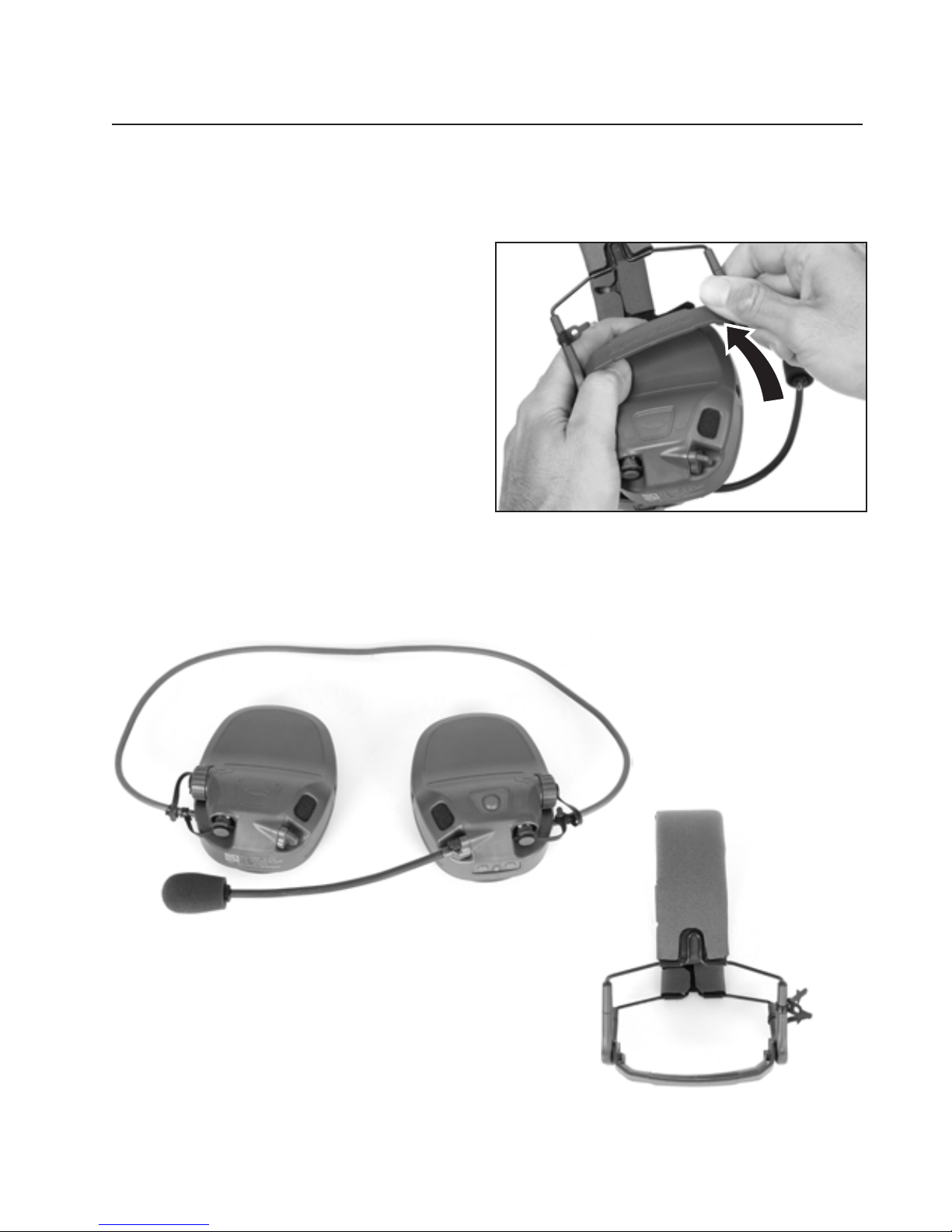
4. Use your index nger to pull
the headband arm towards
you, which will free the earcup
from the headband.
5. Repeat process for the other earcup.
19
Page 22
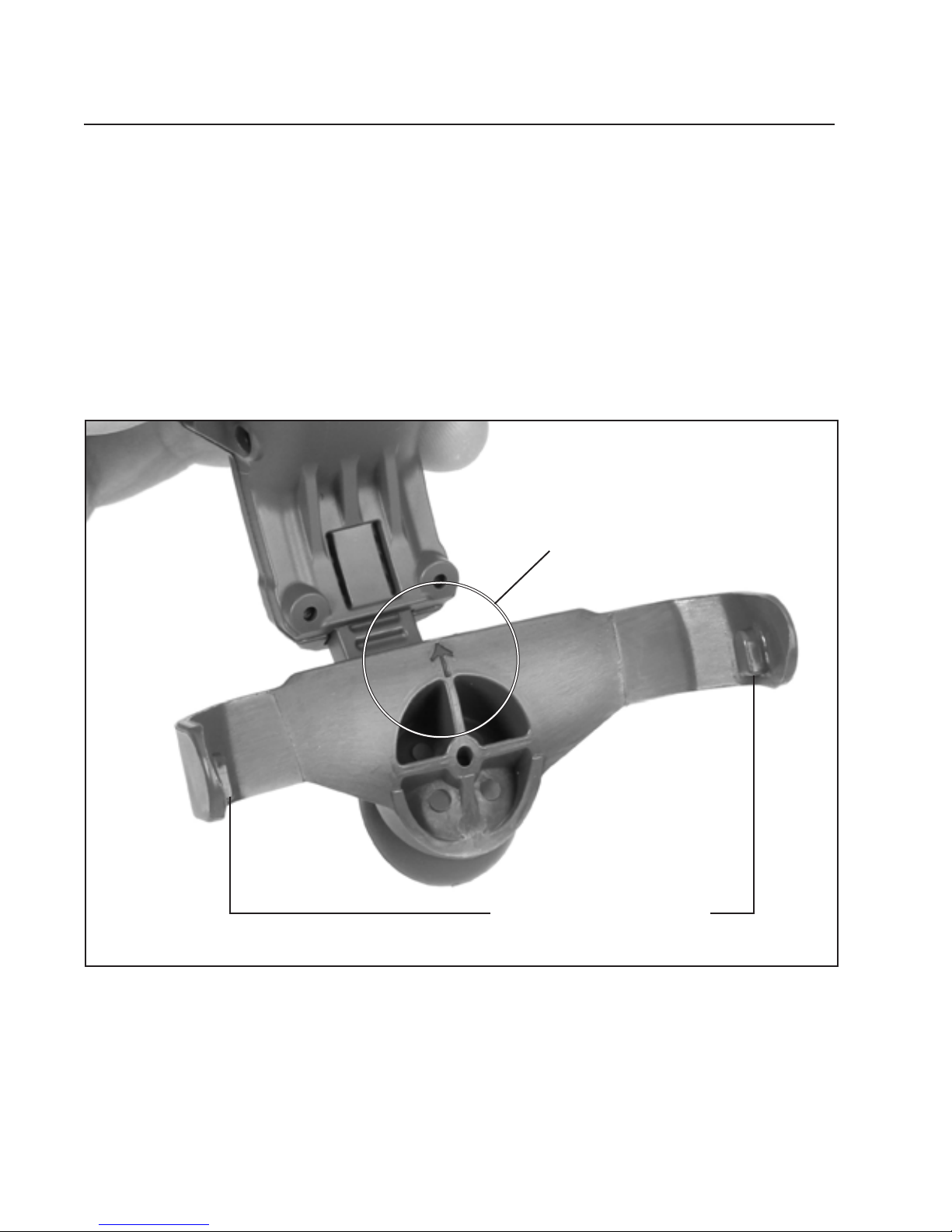
RAIL ARM INSTALLATION
Installing the Headset to the Rail Arms:
1. Align the rail arm with the earcup so that the rail arm strap swivel bulge is
facing down / arrow marker on the inside of the strap is pointing up.
Arrow Faces Up
20
Rail Arm Strap Tabs
Page 23
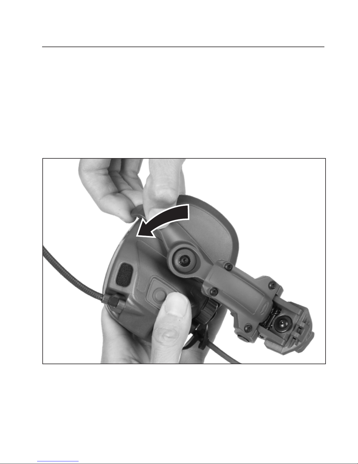
2. Insert one side of the rail arm strap tab into the hole on the side of the earcup
and push down to snap in the opposite earcup strap tab into the hole on the
other side of the earcup. (Repeat for the other earcup).
21
Page 24
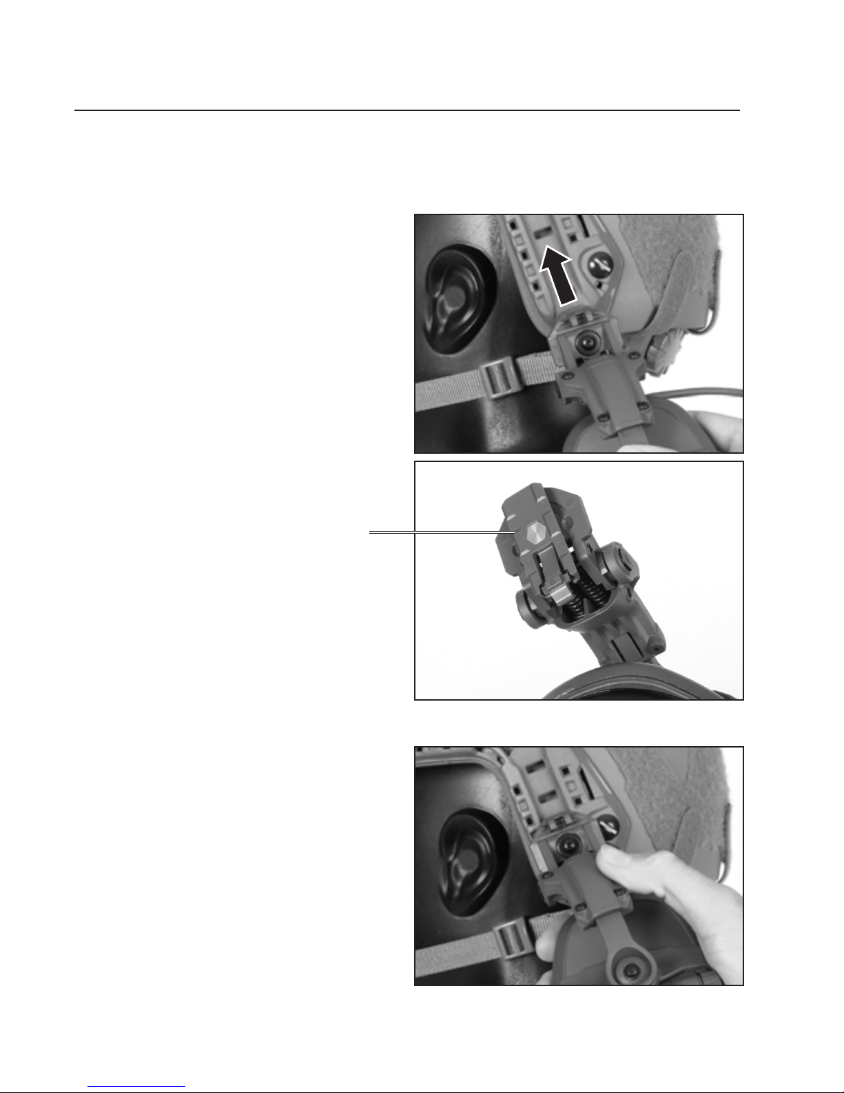
HELMET ATTACHMENT
Attaching the Headset to the Helmet:
1. Rotate the rail arm shoe as
shown and insert it into the
bottom rear portion of the
ARC Rail.
Rail Arm Shoe
2. Push rail arm shoe up until the
tab clicks into the desired
rail slot.
(Repeat steps 1 and 2 for other
earcup)
22
Page 25
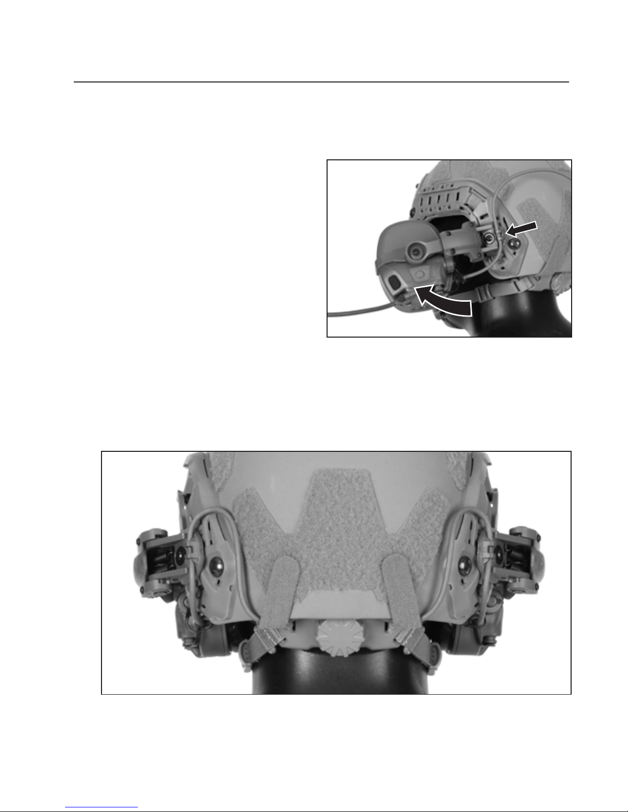
3. Rotate the arm and earcup over
the ear position and insert cable
into cable clip as shown.
(Repeat for the other earcup).
4. Attach cable to helmet as shown using supplied hook and loop fasteners
(see pages 16-17).
23
Page 26
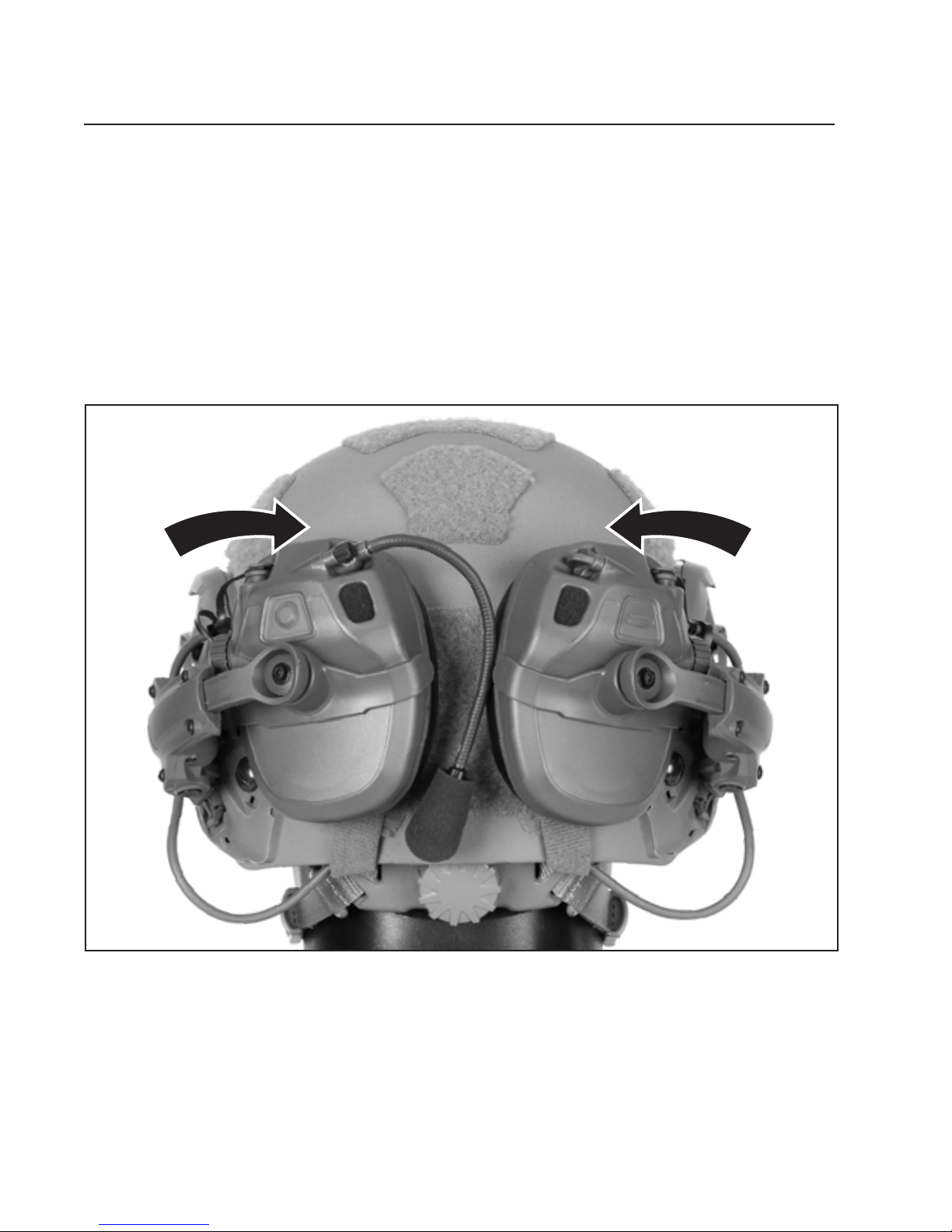
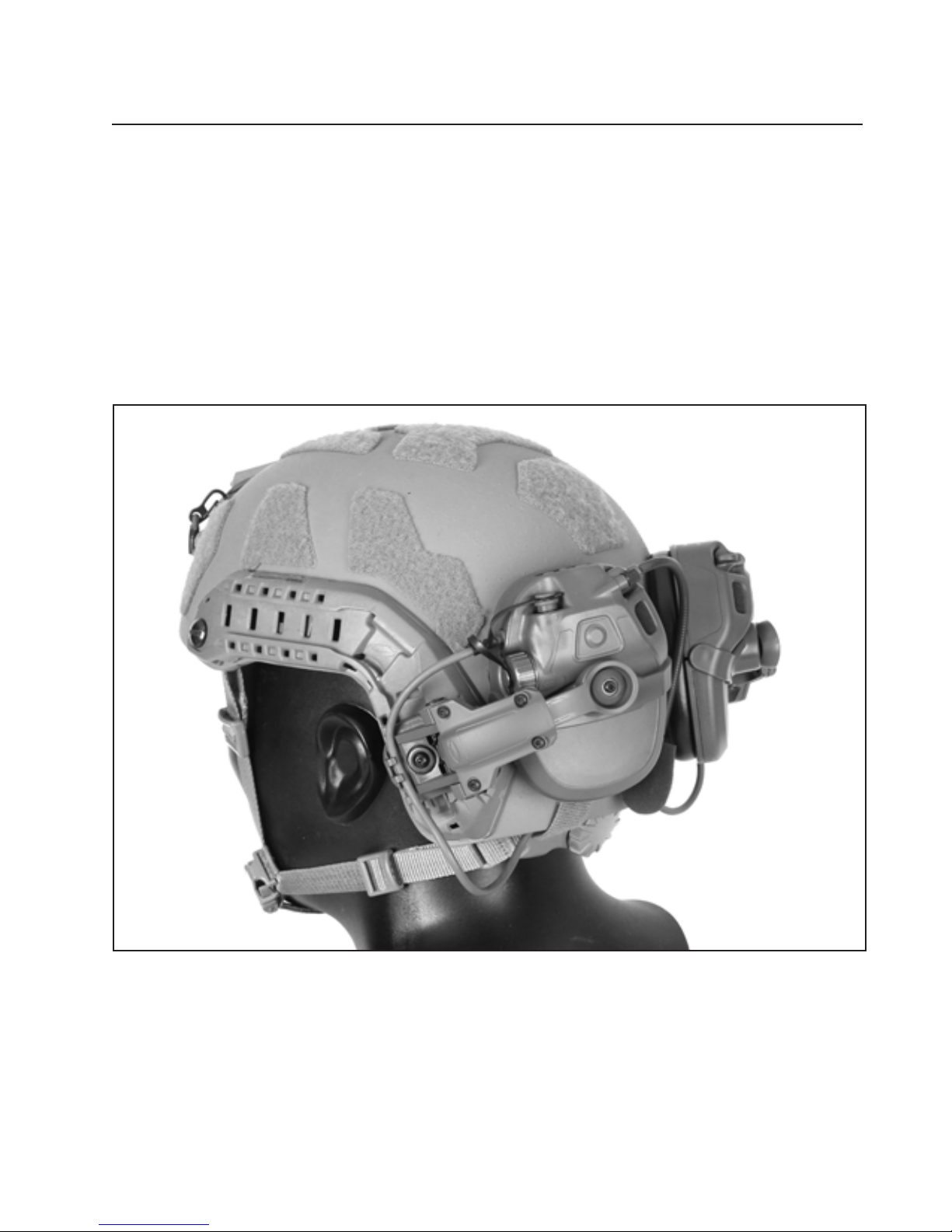
STOWED POSITION
Stowing the Headset on the Helmet
The Headset can be stowed by rotating unit UP and over and folding
earcups to the helmet.
24
Page 27
25
Page 28
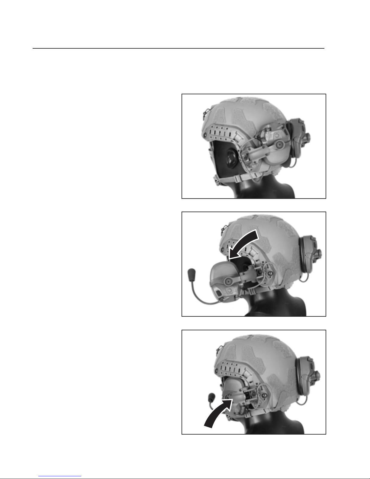
HELMET DONNING / DOFFING
Donning the Helmet and Headset:
1. With the headset in the
stowed position, don the
helmet, fasten the chin strap,
and tighten all straps.
2. Pull earcup out; rotate the
headset earcups over ears.
3. Grasp earcup and push towards
head and center over ear.
26
Page 29
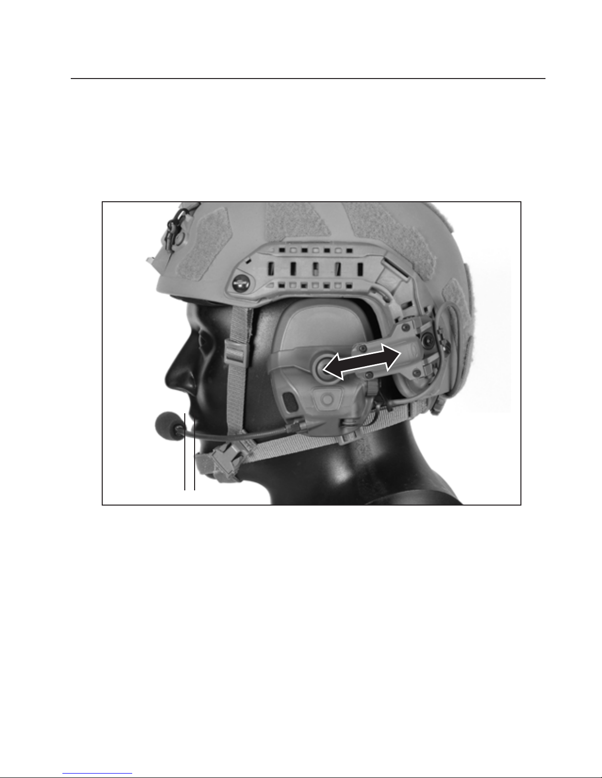
4. Adjust the length of the rail arm so that the earcup is centered over the
ear and adjust the microphone over the mouth (within ¼ inch) for optimal
performance.
Position mic
1/4” from
mouth
Dofng the Helmet and Headset:
1. Pull earcups away from the head until rail arms remain in open position.
2. Unfasten the chin strap, and remove the helmet.
Optional: before or after removing the helmet, the operator may
choose to place the earcups into the stowed position.
27
Page 30
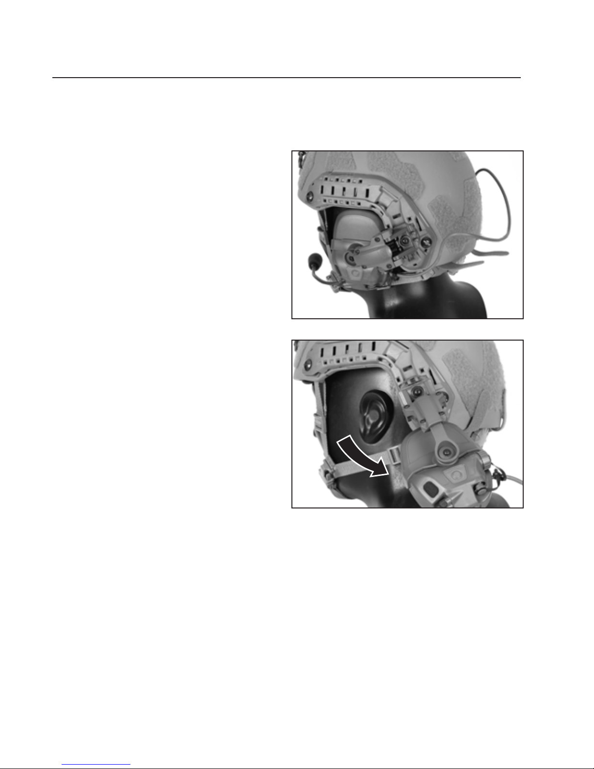
DETACHING RAIL MOUNT ARMS
Detaching the Rail Arms from the Helmet:
1. Detach the cable from both
rail arm cable clips and
from the back of the helmet
shell by detaching the hook
fastener strips.
2. Rotate the earcup down
as shown.
28
Page 31
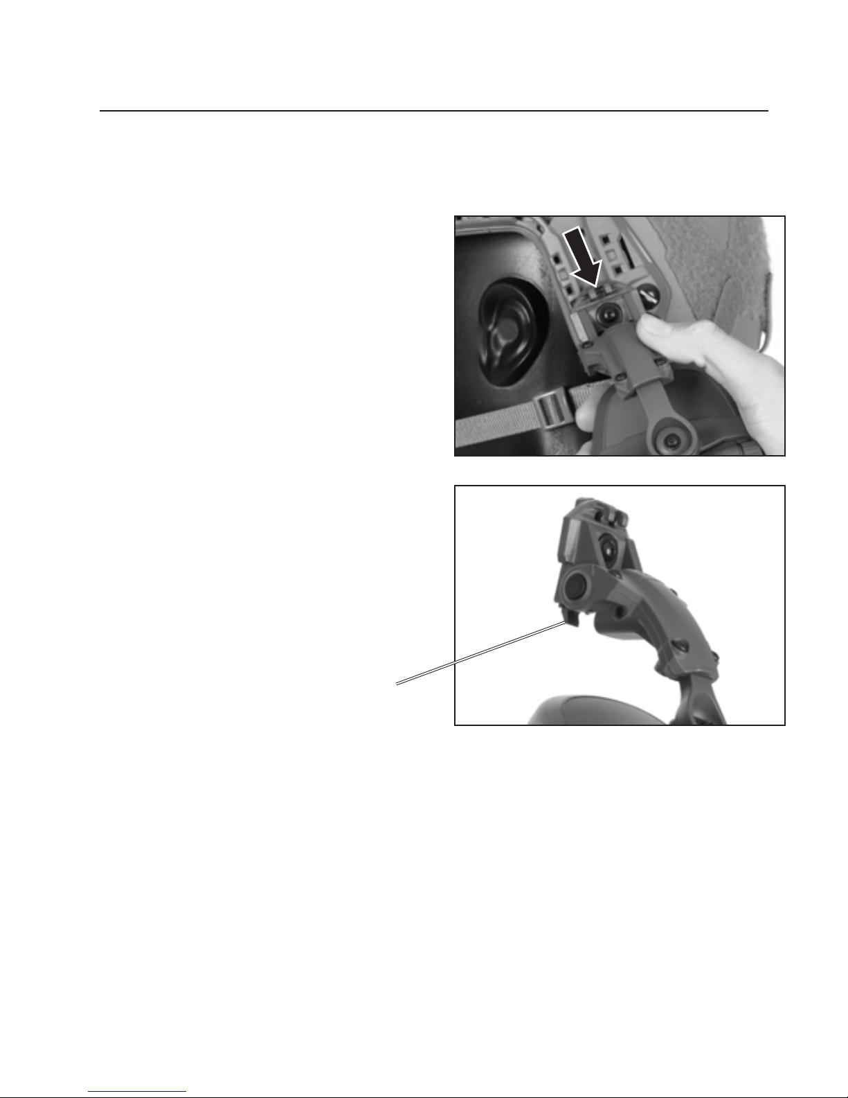
3. Lift the tab up and slide the
rail arm down and out of
the rail.
(Repeat steps 2 and 3 for the
other earcup)
Rail Arm Shoe Tab
29
Page 32
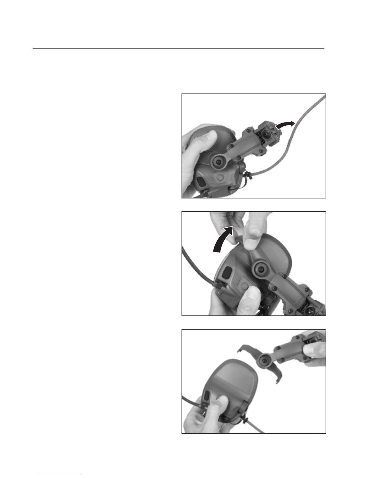
REMOVING EARCUPS FROM RAIL ARMS
Removing the Earcups from the Rail Arms:
1. Remove the ear-to-ear cable
from both cable clips (if still
connected).
2. Grasp one earcup with one hand.
With your other hand, place
your thumb on either the rail
arm strap or gimbal point and
use your index nger to grab the
headband strap at the end tip
where it connects to the earcup.
3. Use your index nger to
pull the strap towards you,
which will free the earcup
from the strap.
30
Page 33
4. Repeat process for the other earcup.
31
Page 34
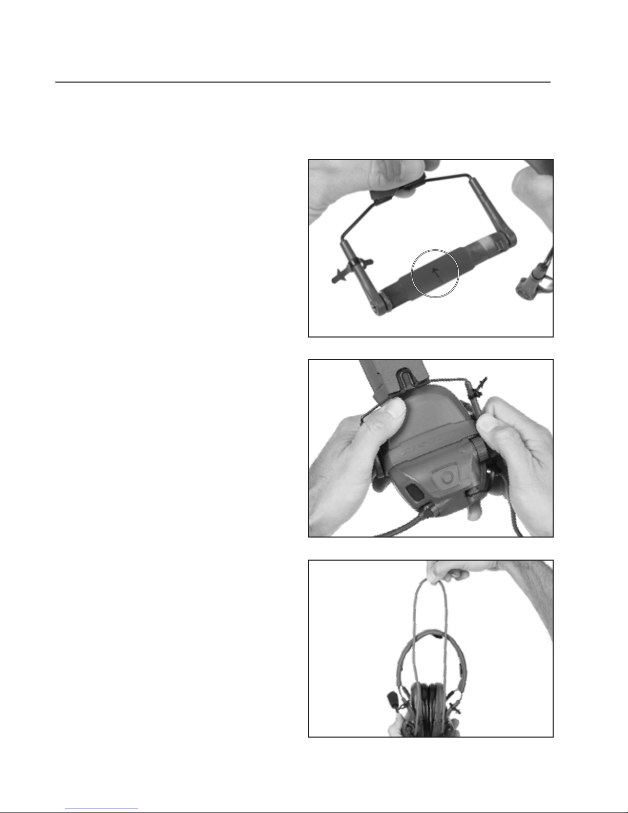
ATTACHING EARCUPS TO HEADBAND
Attaching the Earcups to the Headband:
1. Locate arrow on inside of
headband attachment arm and
ensure that the arrow faces up
when attaching to the earcups.
The headset arm side with the
cable management rubber
straps should be at the rear of
the headset.
2. Attach headband strap outside
of the earcup; snap protruding
element into earcup; repeat on
other side; earcups now attached
to headband.
3. Find / hold center point of
ear-to-ear cable. Fold the middle
cable retention tab over center
Arrow Faces Up
point of cable.
32
Page 35
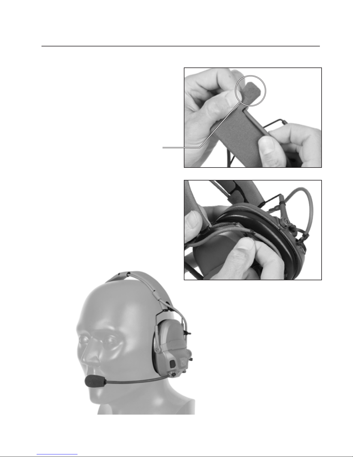
4. Locate cable retention tabs
near base of headband. Secure
the cables with the cable
retention tabs. Repeat at each
end of the headband.
Cable Retention Tabs
5. Wrap cable management strap
around the cable and push tail
through loop to secure. Repeat
for other earcup. Ensure that the
cable is on the outside of the
headband attachment arm.
33
Page 36
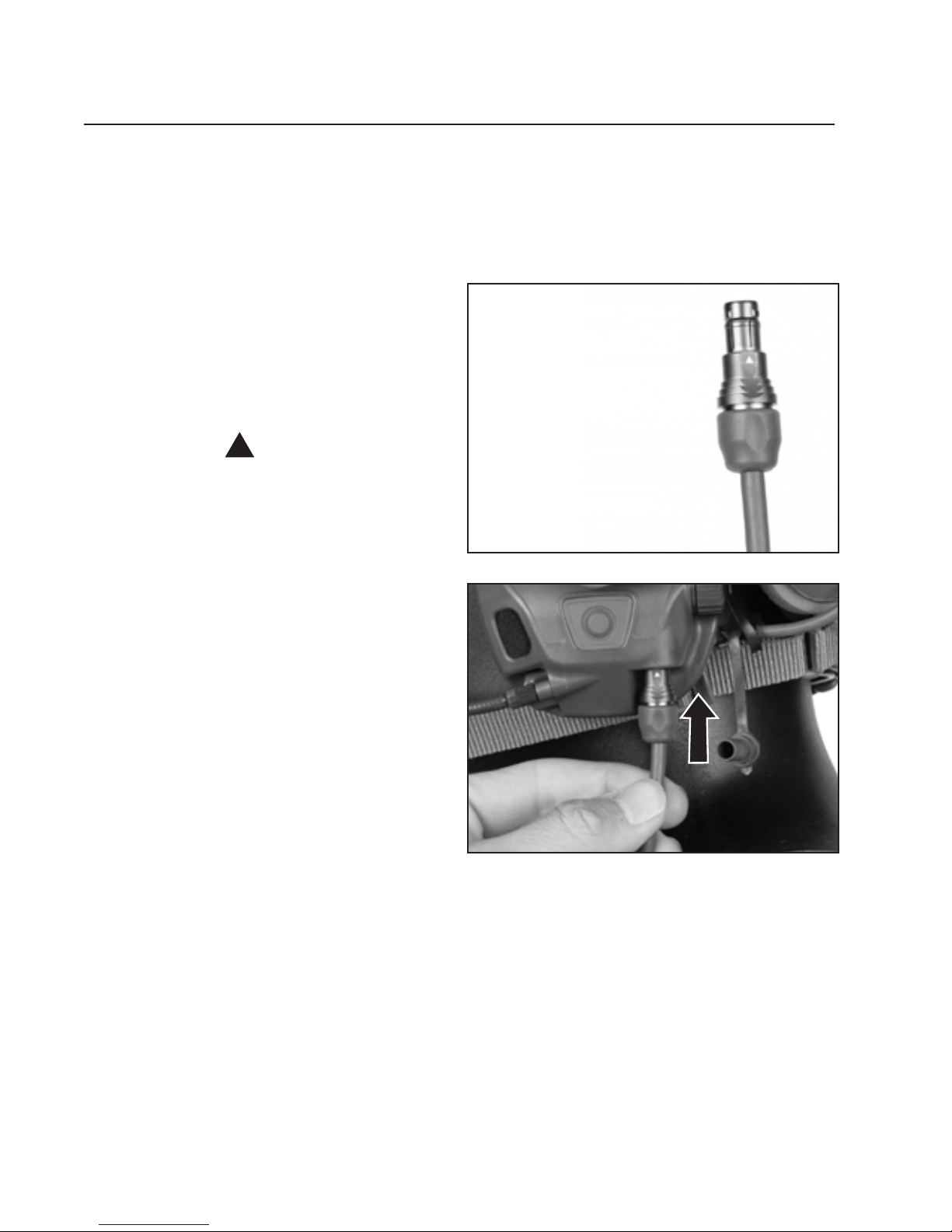
ATTACHING HEADSET DOWNLEAD
Attaching the Headset Downlead (sold separately)
to the Headset:
1. Connect the Fischer connector
end of the downlead cable to
either the left or the right side of
the headset (user’s preference).
The downlead cable will have a
triangular ( ) marking on the
Fischer connector.
Fischer Connector End
34
Page 37

35
Page 38

MAINTENANCE
Maintaining Your Headset:
Simple maintenance will help keep the headset in good operating condition.
Complete the following tasks as necessary.
Inspection
1. Inspect the earseals regularly to ensure that they have no cracks or tears,
which can degrade hearing protection and/or cause discomfort.
2. Inspect boom microphone screw regularly and ensure that it is not loose.
Do not over-tighten screw.
3. Inspect to ensure that hear-through microphone foam is in place and
not protruding.
Cleaning
1. Clean the headset regularly with a soft cloth dampened with soap and water.
2. Dry thoroughly with a clean cloth.
36
Page 39

STORAGE
NOTE: When storing the headset, ensure that the earseals are not
compressed. Long-term compression can deform the earseals, causing
loss of sound attenuation.
1. Remove the batteries before you store the headset for long periods of time.
2. Ensure headset is dry before storing.
3. If possible, store the headset in a cool, dry area. Avoid storing it in areas prone
to excessive heat.
37
Page 40

TROUBLESHOOTING
Hear-through audio is not activating:
1. Assure that the battery caps are tight.
2. Press and hold the + volume button down. If hear-through is off, it will power
on. If the volume is set too low, it will ramp up.
3. If you have a NFMI headset, and are not using the NFMI earplugs, try pressing
the NFMI toggle button to see if audio returns.
4. Replace the batteries with new ones, and repeat starting at step 1.
38
Page 41

CUSTOMER SERVICE
Our dedicated customer service and support professionals are highly trained on
all aspects of our products and are available to assist you with all your needs,
including orders, billing, warranties and returns, accessory questions, replacement
parts, and technical support.
Ops-Core Customer Service
+1 888.894.1755
[email protected]
39
Page 42

SPECIFICATIONS
Noise Protection Ratings
Headset Alone:
NFMI Version (when used with optional
NFMI Earplugs):
Battery Run Time:
NRR 22 dB
SNR 27 dB
H 31 dB
M 23 dB
L 19 dB
NRR 34 dB
SNR 41 dB
H 41 dB
M 39 dB
L 34 dB
Up to 120 Hours w/ Lithium Batteries
Battery Run Time w/ NFMI engaged :
Salt Water Immersion:
Environmental:
Operating Temperature:
Storage Temperature:
EMI Testing Standards:
@ 21°C
Up to 80 Hours w/ Lithium Batteries
@ 21°C
IPX7
MIL-STD-810G
-40°C to +55°C (-40°F to +131°F)
with lithium batteries
-40°C to +71°C (-40°F to +160°F)
MIL-STD-461G
40
Page 43

Weight Headband Conguration
(w/ batteries):
Weight Rail Mounted Conguration
(w/ batteries):
Weight NFMI Version,
Headband Conguration
(w/ batteries):
Weight NFMI Version,
Rail Mounted Conguration
(w/ batteries):
0.85 lbs (386 g)
0.94 lbs (426g)
0.92 lbs (419g)
1.01 lbs (460g)
41
Page 44

OPERATOR NOTES
42
Page 45

OPERATOR NOTES
43
Page 46

OPERATOR NOTES
44
Page 47

OPERATOR NOTES
45
Page 48

Copyright © 2018 Gentex Corporation. Ops-Core is a registered trademark of
REV. 20181012
Gentex Corporation or its afliates.
 Loading...