

Oppermann Regelgeräte KRM-1, KRM-2, KRM-2-MOD Technical Data Manual
Duct Smoke Sensor KRM®
Technical Data
Sensor: Scattering RM 3.3 (ALK-E)
Supply voltage KRM-1:
230 V AC ± 10 %, 50/60 Hz
Supply voltage KRM-2/KRM-2-MOD:
24 V AC/DC +15 % / -10 %
Rated current: KRM-1: 30 mA
KRM-2/KRM-2-MOD: 120 mA
Relay outputs: oating
Alarm relay locked: 1 changeover contact, 8 A,
250 V AC or 24 V DC
1 NC, 8 A, 250 V AC or 24 V DC
Contamination relay:
Operating temperature:
Permissible humidity:
Protection class:
(water resistant housing)
Approvals:
Sensing chamber and
air duct frames: VdS approval G210059
Tested:
according to FprEN54-27
LED display:
at > 70 %
LED in housing:
blue lack of air ow
yellow failure, electronics,
smoke detector defective,
low voltage
red smoke alarm, including
contamination > 99 %,
ashes at attempts to release
when the sensing chamber is
not empty
Adaptergehäuse: ABS
Air measuring tube:
shortest length 160 mm
standard length 600 mm
Dimensions:
Screw connection:
% contamination level ashes
257 x 166 x 77 mm (L x W x H)
1 NC contact, 6 A, 250 V AC or 24 V DC
-10 °C - +50 °C
10 - 95 % non-condensing
IP 54, IP 65 with WDG
green operating
Aluminium / plastic
3 x M16
• VdS certication (G210059)
• Patented single tube air sampling system
• Contamination display in %
and signalling at 100 %
• Electronic air ow control
• Externally operable reset button in the
housing
• Remote reset option via terminals
• Long service life, low contamination
Accessories
Mounting bracket: KS (for insulated / circular ducts)
Housing: waterresistant housing for outdoor
installation and increasing protection
class to IP 65
Function
The KRM duct smoke detector is designed for smoke detection
in ventilation ducts. It constitutes a combination of a smoke
detector with an adapter system, whose measuring tube and
housing have been specially adapted for optimal air ow through
the smoke detector.
The multi-chamber measuring tube in the air duct transports the
air within the air duct along the entire length of the tube, through
the sensing chamber and back into the air duct. Upon detection
of smoke, the sensor reacts immediately and triggers an alarm.
Over time, the sensor becomes contaminated. Because of alarm
threshold tracking, the sensitivity up to total pollution remains
the same. From 70 % contamination upwards, the sensor is triggered and indicates this by ashing. If the sensor is not replaced
the smoke alarm is triggered at 99 % contamination.
The contamination level is indicated in a two-line LED display; at
> 70 % it ashes.
To verify operability, the device is equipped with electronic air
ow monitoring, which lights a blue LED at < 1 m/s. The failure
LED illuminates when the smoke sensor or the electronics are
defective, in the absence of a smoke sensor, and with shortcircuits or cable breakage.
The smoke alarm must be released with the reset button.
A functionality test is also possible with the same button.
The operation functions like a smoke alarm.
Furthermore, the same function takes place on restart or when
the bridge circuit between terminals 9 and 10 is opened (remote
release).
Fire Protection | Data sheet No. 41300 | Version 01-2011 | 1 | 8
Duct Smoke Sensor KRM
10
9
11
12
13
8
6
5
7
1
14
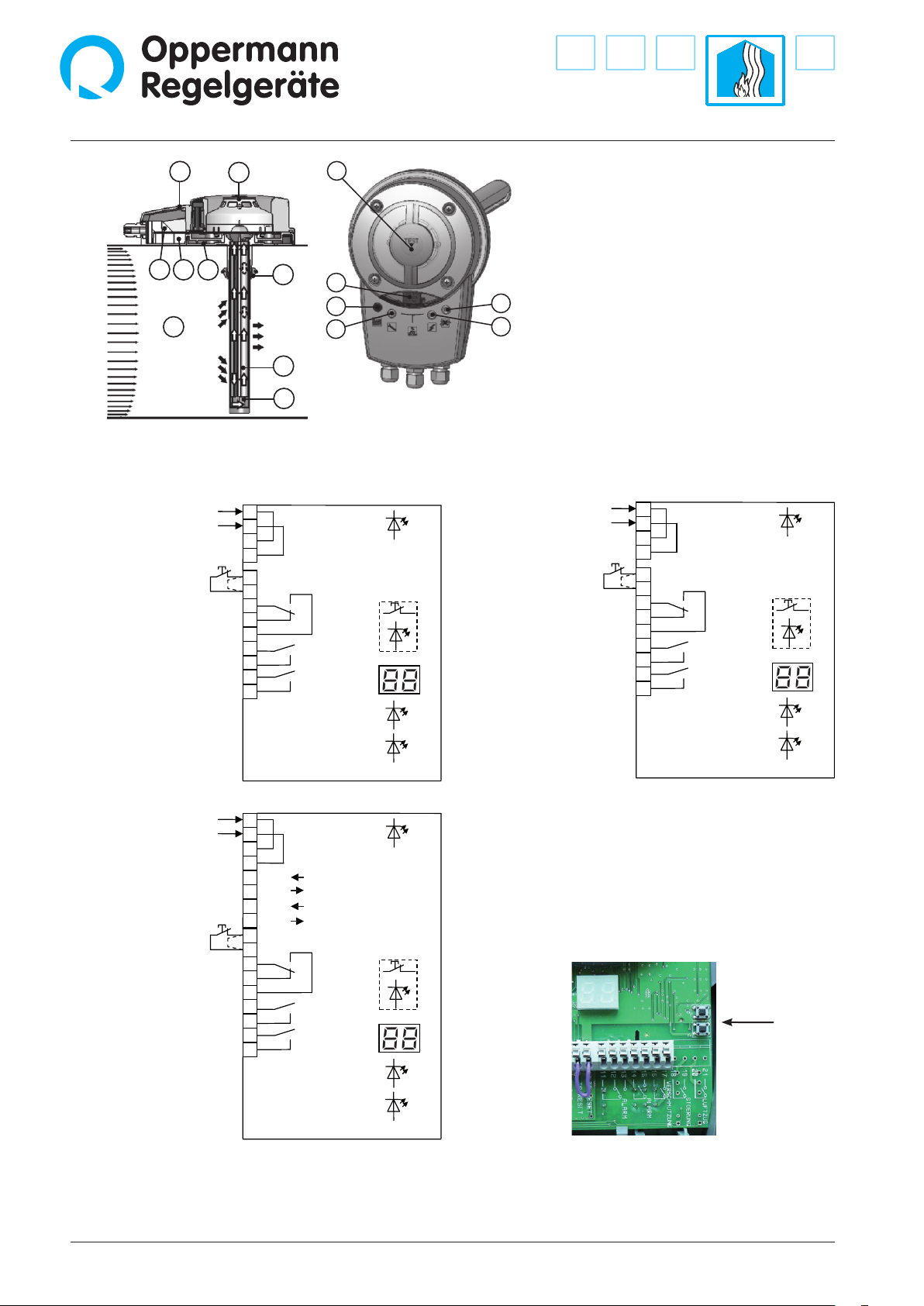
Electrical connection
Power supply
230 V AC
Test/Reset
1
2
3
4
9
10
11
12
13
14
15
16
17
4
2
3
Power supply
230 V AC
Smoke alarm
Service signal
Contamination
14
11
9
10
Smoke alarm
Test/Reset
green
red
yellow
13
12
1 Adapter plate with gasket
2 Patented measuring tube (max. length 3 m)
3 End cap
4 Rubber bushing
(only for insulated or circular ducts)
5 Lower housing with seal
6 Electronics
7 Optical smoke sensor
8 Upper casing with seal
9 Red LED: alarm / reset button
10 Yellow LED: interference
11 LED display: % of sensor contamination
12 LED green: in operation
13 LED blue: air ow under 1 m / s
14 Opening for test gas
15 Air duct
10
11
12
13
14
15
16
17
1
2
3
4
9
Power supply
230 V AC
Smoke alarm
Smoke alarm
Service signal
Contamination
Power supply
24 V AC/DC
Test/Reset
green
Test/Reset
red
yellow
blue
Power supply
24 V AC/DC
Test/Reset
KRM-2-MOD, 24 V
10
11
12
13
14
15
16
17
1
2
3
4
5
6
7
8
9
KRM-1
Bus B
Bus B
Bus A
Bus A
Power supply
24 V AC/DC
Smoke alarm
Smoke alarm
Service signal
Contamination
Test/Reset
blue
green
red
yellow
KRM-2, 24 VKRM-1, 230 V
KRM-2
Programming the Bus address for the KRM-2-Mod:
Press buttons T3+T4 on the circuit board (to the right, next to the
display) at the same time, so that the display changes from contamination level to show the bus address (the display will ash).
Press button T3 or T4 to adjust the desired address (1-99). The last
set bus address is automatically saved. The display resets automatically after 3 seconds or by simultaneously pressing T3+T4.
Contact depictions are with the
power o (alarm)
KRM-2-MOD
Notes: The oating switching contacts (terminals 11-17) are uniformly assigned to an installation category according to EN 60730-1.
blue
These switching contacts are only to be used for 230 V AC or 24 V AC/DC, a combination is not permitted.
A mixed connection of safety extra-low voltage (SELV) and low voltage must not occur. The assembly may only be operated on one mains
phase.
2 | 8 | Fire Protection | Data sheet No. 41300 | Version 01-2011
Duct Smoke Sensor KRM
Installation Instructions
Install the detector where ow meters, etc. are normally xed,
so that the air ow can run in a laminar manner with the measuring tube. Follow the installation instructions. All work must be
carried out by suciently qualied craftsman.
Current local rules and regulations (e.g. building regulations,
elecrical/VDE guidelines, etc.) are to be observed. Installers
and operators are required to be adequately informed before
operation. We assume no liability for misprints and changes
after printing. Compliance with operating and installation
instructions is also included within the regulations of intended
use. We assume no liability for damages caused by improper
use. Operating licenses and guarantees and all warranty claims
will be voided in the event of unauthorized modications or any
tampering with the device.
Maintenance
Targeted maintenance can be carried out since the smoke
detector is equipped with a contamination indicator. From a
70 % contamination level or higher the smoke sensor must
be changed. There is a contact available for this signal, and it
should be connected to the automation station.
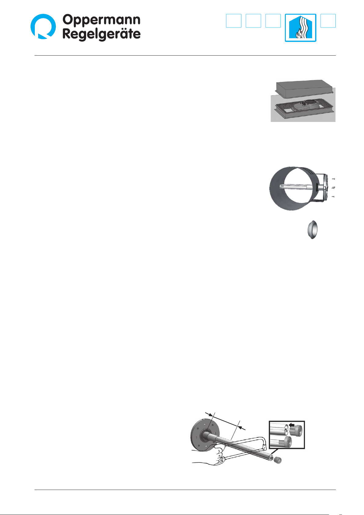
Accessories
Splash-proof housing (type
WDG) for outdoor installation
to prevent condensation. The
housing is lined with insulating foam.
Mounting bracket
Type KS is required if the duct smoke sensor must be mounted on round air ducts. The
bracket can also be used with
insulated rectangular ducts.
For this the adapter is mounted with the air measuring
tube before insulation.
Installation and positioning
1.
We recommend that the duct smoke detector be installed at the
same distance to heating, cooling and humidity equipment and
be mounted similarly to ow sensors. The distance of the smoke
sensor to ttings, valves, lters, etc., should be 3 times the diagonal length of the cross-section of the duct when going against
the air ow, and 5 times the diagonal length with the ow.
2.
Drill a hole of 43-44 mm in diameter at the intended mounting
location.
Note: Installation of the TurboTube measuring tube is possible
either from the top, bottom or side of the channel for all duct
cross-sections (for round ducts as well).
Fire Protection | Data sheet No. 41300 | Version 01-2011 | 3 | 8
3.
• Determine how long the measuring tube must be.
The TurboTube measuring tube must be inserted into the
duct at least to the middle of the duct‘s cross-section.
• If necessary, shorten the tube. Minimum length 160 mm.
• Deburr the cutting face and put the end plug back on up
to the stop collar.
Min. 160 mm Attention:
Operation without
end plug not
permitted.
 Loading...