

Page 1

Biopel v9
User manual
Biopel pellet boilers are boilers fulfilling stringent requirements for ecological heating with low combustion
emissions. It allows you to operate all electrical heating system components and connection of many types of
additional devices operated by boiler control unit. You can find full list of possible accessories inside this manual.
User manual includes all needed information about installation, startup and maintenance of all types of Biopel
boilers, from 10 to 200kW of power. Information included in this manual are intended to both installer and end user.
Chapters are written chronologically, starting with boiler installation, first start up and proper setup, to regular
maintenance. Read all information included inside this manual carefully.
Each Biopel boiler can be connected to our online server to use remote control features for both boiler and heating
system components. Online features are for free included in basic package of Biopel boilers. For more information,
ask your supplier about how to connect your boiler to the internet.
We believe that you will be satisfied with our product for its long working life. For more information about this boiler
and our company use not only this manual but also our network of representatives in your country as well as main
staff of OPOP, Czech Republic.
Page 2

CONTENT
1. INTRODUCTION ......................................................................................................................................................... 4
2. BASIC DESCRIPTION OF BIOPEL LINE BOILERS .......................................................................................................... 4
3. MAIN PARAMETERS .................................................................................................................................................. 5
3.1. Biopel 10 - 40kW ............................................................................................................................................... 5
3.2. Biopel 60 - 80kW ............................................................................................................................................... 6
3.3. Biopel 100 - 200kW ........................................................................................................................................... 7
3.4. Burner ............................................................................................................................................................... 8
3.5. Pellet tank ......................................................................................................................................................... 8
3.6. External feeder .................................................................................................................................................. 8
4. BASIC COMPONENTS OF BIOPEL INSTALATION ........................................................................................................ 9
4.1. Biopel 10 - 40kW ............................................................................................................................................... 9
4.2. Biopel 60 - 80kW ............................................................................................................................................. 10
4.3. Biopel 100 - 200kW ......................................................................................................................................... 11
4.4. Burner ............................................................................................................................................................. 13
4.5. Pellet hopper ................................................................................................................................................... 14
4.6. External feeder ................................................................................................................................................ 14
5. INSTALTION PROCESS.............................................................................................................................................. 15
5.1. Biopel 10 – 80kW ............................................................................................................................................ 17
5.2. Biopel 100 – 200kW ........................................................................................................................................ 18
5.3. Pellet tank ....................................................................................................................................................... 19
5.4. Burner ............................................................................................................................................................. 19
5.5. External feeder ................................................................................................................................................ 20
5.6. Control unit v9 and connection board ............................................................................................................ 20
5.7. Electrical connections ..................................................................................................................................... 21
6. CONTROL UNIT v9 ................................................................................................................................................... 24
6.1. Basic navigation .............................................................................................................................................. 24
6.2. Main operation modes .................................................................................................................................... 25
7. CONTROL UNIT’S MENU LAYOUT ............................................................................................................................ 26
7.1. First start ......................................................................................................................................................... 26
7.2. Ignition / Extinction ......................................................................................................................................... 26
7.3. Main settings ................................................................................................................................................... 26
7.4. Fitters menu .................................................................................................................................................... 28
7.5. Service menu ................................................................................................................................................... 36
7.6. Language selection .......................................................................................................................................... 38
8. FIRST START ............................................................................................................................................................. 39
9. COMBUSTION ADJUSTMENT .................................................................................................................................. 42
9.1. Flame parameters ........................................................................................................................................... 42
9.2. Change fan speed ............................................................................................................................................ 42
Page 3

9.3. Change operation time of external feeder ..................................................................................................... 43
9.4. Non standard installation ................................................................................................................................ 44
10. HEATING SYSTEM EXAMPLES .................................................................................................................................. 45
10.1. One CH circuit + DHW ................................................................................................................................. 45
10.2. Two CH circuits + DHW ............................................................................................................................... 46
11. REGULAR MAINTENANCE ........................................................................................................................................ 49
11.1. Biopel 10 - 80kW ......................................................................................................................................... 49
11.2. Biopel 100 - 200kW ..................................................................................................................................... 50
11.3. Burner 10 - 200kW ...................................................................................................................................... 50
12. BIOPEL ONLINE ........................................................................................................................................................ 51
13. FIRMWARE UPDATE ................................................................................................................................................ 51
14. OPERATIONAL AND ALARM MESSAGES .................................................................................................................. 52
15. SOLUTIONS TO SPECIFIC SITUATIONS ..................................................................................................................... 53
16. FACTORY SETTINGS ................................................................................................................................................. 56
17. WARRANTY CONDITIONS, GENERAL INFORMATION .............................................................................................. 58
18. STANDARDS AND REGULATIONS ............................................................................................................................ 59
19. WARRANTY CARD .................................................................................................................................................... 60
Page 4

1. INTRODUCTION
Reed this manual step by step, each chapter from the beginning to the end, to make sure installation and start-up is made
properly. You make sure your boiler runs at its best if you read all information included in this manual. Chapters describe first
boiler installation, than chronologically accessories connection and activation and boiler maintenance. Manual describes all
important steps and describes practical information for each chapter, so it helps customer to understand activity of all boiler and
heating system components.
In the second half of this manual is full heating system examples including electrical components such as pups and mixing valves
and step by step description how to connect and activate these components inside v9 controller menu. Use this manual to
connect and setup all accessories properly so boiler operation will be in in accordance with user manual.
If you need more information about boiler function, do not hesitate to contact OPOP business partners in your country or
directly OPOP staff. We will gladly tell you all the information you want to know.
2. BASIC DESCRIPTION OF BIOPEL LINE BOILERS
Biopel boilers are produced in several sizes, from 10 to 200kW. Boiler is operated by v9 control unit which regulates also all
electrical components of heating system, if connected into the connection board in the front of the boiler. There are many
advanced features implemented inside v9 controller which allows customer to use his boiler as he requires.
V9 controller allows following:
2 mixing valves operation.
2 room thermostats for 2 separate heating circuits.
5 pumps – central heating pump (CH pump), domestic hot water pump (DHW pump), valve pump 1, valve pump 2,
additional pump with configurable settings.
Weather compensation based on the outside temperature sensor.
CH temperature time control - programmable weekly operation mode.
Buffer tank operation with use of 2 temperature sensors.
Online remote control by our OPOP online server: opop.emodul.eu.
Firmware update via USB key to upload new features.
Additional output for boiler activation by solar heating device.
Despite this, v9 controller allows connection of wide range of additional devices, which makes boiler operation and maintenance
more automatic. List of all additional accessories is listed below:
RT10 room thermostat, displaying information of full hydraulic system connection.
Compressor cleaning of burner, extending significantly intervals for manual cleaning.
Automatic ash removal, extracting ash from bottom part of the boiler into the external container. You don’t need to
remove ash from the boiler to often if you install this device.
Automatic exchanger cleaning, which moves turbulators inside the boiler up and down and cleans heat exchanger. All
the ash drops down to the ashtray and can be removed automatically by automatic ash removal system.
Lambda sensor, measuring remaining oxygen inside the boiler and adjusting combustion to make it more efficient.
GSM module, which can change boiler operation by sending sms messages on sim card inside this module.
Vacuum transport, transferring pellets from external silo inside standard pellet tank next to the boiler.
Cascade controller, allowing you to operate up to 4 boilers connected together and make big boiler rooms more
efficient.
Exhaust fan, to increase chimney draft if chimney is not high enough to support proper boiler operation.
These devices can be installed anytime, even after boiler installation. Ask your installer for more information about each
accessories if you consider using these with your boiler. We will also gladly help you to explain and suggest possibilities how to
make your boiler even more automatic and efficient.
Page 5

3. MAIN PARAMETERS
Main components of basic installation are boiler, burner and fuel storage tank. You can find main parameters for each
component down below, including also diameters and other important values.
3.1. Biopel 10 - 40kW
Boiler body is always different according its maximum power. Main differences are external dimensions, connection outlets
and inlets, flue gas outlet diameter, heat exchanger size and number of doors attached on the boiler body.
Technical parameters:
Biopel 10
Biopel 15
Biopel 20
Biopel 30
Biopel 40
Maximum power
kW
10,32
14,5
19,43
31,5
42,48
Minimum power
kW
2,99
3,7
4,7
8,5
11,4
Warranty fuel
Wood pellets 6-8 mm
Fuel consumption (max power)
kg/h
2,5
3,4
4,4
7,2
9,96
Fuel consumption (min power)
kg/h
0,71
0,85
1,1
1,9
2,66
Emmision class *1
5
Efficiency *1
%
89,94
91,4
92,82
92,2
91,41
Water volume
L
43
59,3
83
Recommended chimney draft
Pa
5-10
5-12
5-15
10-20
10-20
Maximum water pressure
during operation
Bar
2
Maximum water temperature
in the boiler
°C
85
Minimum return water
temperature
°C
65
Flue gas temperature (durning
max. boiler power)
°C
70
73
77
87
97
Weight
kg
198
198
228
228
300
Supply voltage
V/Hz
230V/50Hz ±10%
Dimensions:
Boiler height
mm
1054
1154
Boiler width
mm
455
555
655
Boiler depth
mm
773
838
936
Flue gas outlet position from
the ground
mm
708
808
Inlet water position from the
ground
mm
178
Outlet water position from the
ground
mm
868
968
Counnecting diameters of
water outlet and inlet
DN
G1 1/4"
Flue gas outlet diameter
mm
130
150
*
1
Emission parameters are measured according the EN 303-5 standards.
Page 6

3.2. Biopel 60 - 80kW
Boiler body is always different according its maximum power. Main differences are external dimensions, connection outlets
and inlets, flue gas outlet diameter, heat exchanger size and number of doors attached on the boiler body. Biopel 60-80kW
can be installed only with external version of pellet tank.
Technical parameters:
BIOPEL 60
BIOPEL 80
Maximum power
kW
63,5
84,4
Minimum power
kW
15,5
19,96
Warranty fuel
Wood pellets 6-8 mm
Fuel consumption (max
kg/hod
15,1
20,1
Fuel consumption (min
kg/hod
3,9
5,2
Emmision class *1
5
5
Efficiency *1
%
90,6
90,1
Water volume
l
95
130
Recommended chimney draft
Pa
10-15
Maximum water pressure
during operation
Bar
2
Maximum water temperature
in the boiler
°C
85
85
Minimum return water
temperature
°C
65
65
Flue gas temperature (durning
max. boiler power)
°C
117,8
131,9
Weight
kg
385
480
Supply voltage
V/Hz
230V/50Hz ±10%
Dimensions:
Boiler height
mm
1312
Boiler width
mm
641
743
Boiler depth
mm
949
1049
Flue gas outlet position from
the ground
mm
1007
1007
Inlet water position from the
ground
mm
90
90
Outlet water position from
the ground
mm
1171
1164
Counnecting diameters of
water outlet and inlet
DN
G1 1/4"
Flue gas outlet diameter
mm
150
178
*
1
Emission parameters are measured according the EN 303-5 standards.
Page 7

3.3. Biopel 100 - 200kW
This size of Biopel has horizontal pipe type of heat exchanger. Its dimensions, way of installation and connection diameters
of water inlet and outlet are also different than Biopel 10-80kW. Read exact values in the table below.
Technical parameters:
BIOPEL 100
BIOPEL 150
BIOPEL 200
Maximum power
kW
107,1
154,5
201,4
Minimum power
kW
28,7
44,5
59,9
Warranty fuel
Wood pellets 6-8 mm
Fuel consumption (max power)
kg/hod
25,2
35,2
45
Fuel consumption (min power)
kg/hod
6,7
10,3
13,9
Emmision class *1
4 5 5 Efficiency *1
%
90,9
91,8
95,5
Water volume
l
690
950
1190
Recommended chimney draft
Pa
10-15
Maximum water pressure during
operation
Bar
2
Maximum water temperature in the
boiler
°C
85
85
85
Minimum return water temperature
°C
65
65
65
Flue gas temperature (durning max.
boiler power)
°C
95,8
92,6
93,5
Weight
kg
1414
1740
2133
Supply voltage
V/Hz
230V/50Hz ±10%
Dimensions:
Boiler height
mm
1919
Boiler width
mm
1560 / 1198
Boiler depth
mm
1660
2060
2460
Flue gas outlet position from the
ground
mm
1886
Inlet water position from the ground
mm
606 / 70
Outlet water position from the
ground
mm
676 / 217
Counnecting diameters of water
outlet and inlet
DN
G 1 1/2" / G 2 1/2"
Flue gas outlet diameter
mm
199
*
1
Emission parameters are measured according the EN 303-5 standards.
Page 8
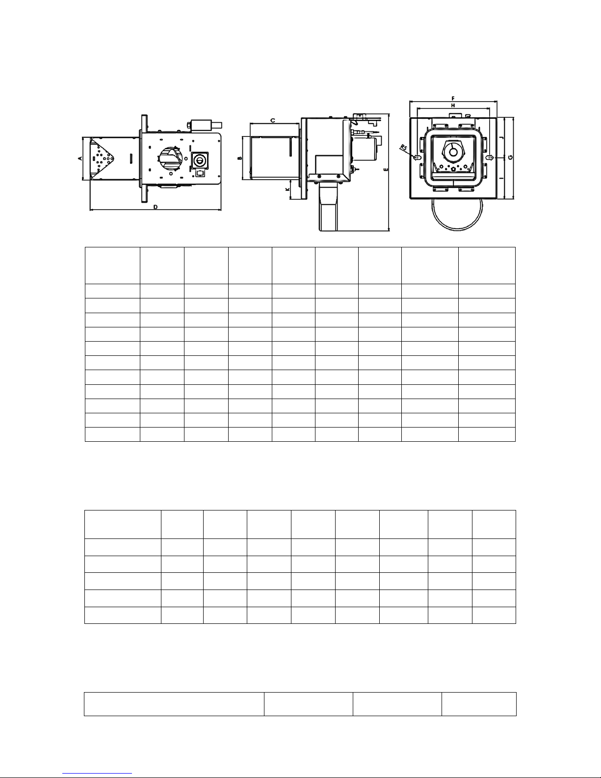
3.4. Burner
Pellet burner is different the same way as a boiler body, according to the maximum power. Differences are mainly in burner
dimensions, types of electrical components and types of burner grates which are also different according to the burner size.
Dimensions
mm
Biopel
burner
10
Biopel
burner
15
Biopel
burner
20
Biopel
burner
30
Biopel
burner
40
Biopel
burner
60
Biopel
burner 80-
100
Biopel
burner 150-
200
A
116
116
145
177
183
183
213
324
B
116,6
116,6
116,6
171
173,8
173,8
198,8
224
C
132
177
221
250,7
322,6
322,6
360,9
523,6
D
354
399
446,1
500
573
602
637
842,4
E
316,5
316,5
319,1
380,3
390,8
457,8
476,8
477,4
F
236
236
240
278
333
333
340
453
G
220
220
240
278
273
273
299
298
H
195
195
204
248
306
306
306
412
I
111,5
111,5
120
139
144
144
150
147,5
J
108,5
108,5
120
139
129
129
149
150,5
K
53
53
70,4
58,5
43
43
50
37
3.5. Pellet tank
Pellet tanks are divided to 2 main types. Compact version can be used with boilers from 10 to 40kW, external versions can
be used for all Biopel types.
Pellet tank type
cm
External
60x60
External
80x80
External
100x100
External
1420x80
Compact
big
Compact
middle
Compact
small
Volume of pellets
kg
110
220
300
350
250
150
60
Weight
kg
25
29
35
38
95
55
Height
mm
1300
1300
1300
1300
1210
1210
1210
Width
mm
600
815
1000
1420
653
507
507
Depth
mm
600
815
1000
815
1180
995
3.6. External feeder
External feeder is used only with external tank configuration. Compact tank has feeder already installed inside. You can
choose two sizes – 2 or 3m length.
External feeder type
m 2 3
Page 9
4. BASIC COMPONENTS OF BIOPEL INSTALATION
Biopel is produced in several sizes depending on maximum power, form 10 to 200kW. Each size has its differences, speaking not
only about dimensions, but also design of heat exchanger, doors, connection dimensions of inlets, outlets, flue gas outlets.
Boiler size is also influenced by burner dimensions, pellet tank type which you selected, external feeder size and other. You can
read about each main part of Biopel installation set below in next chapters.
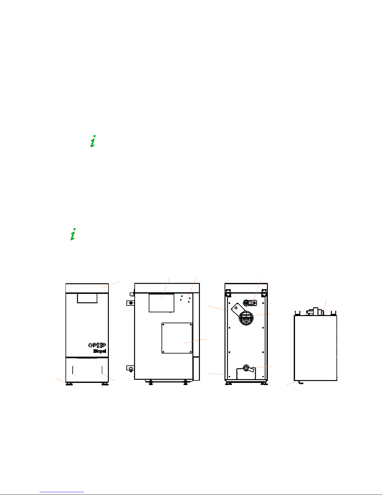
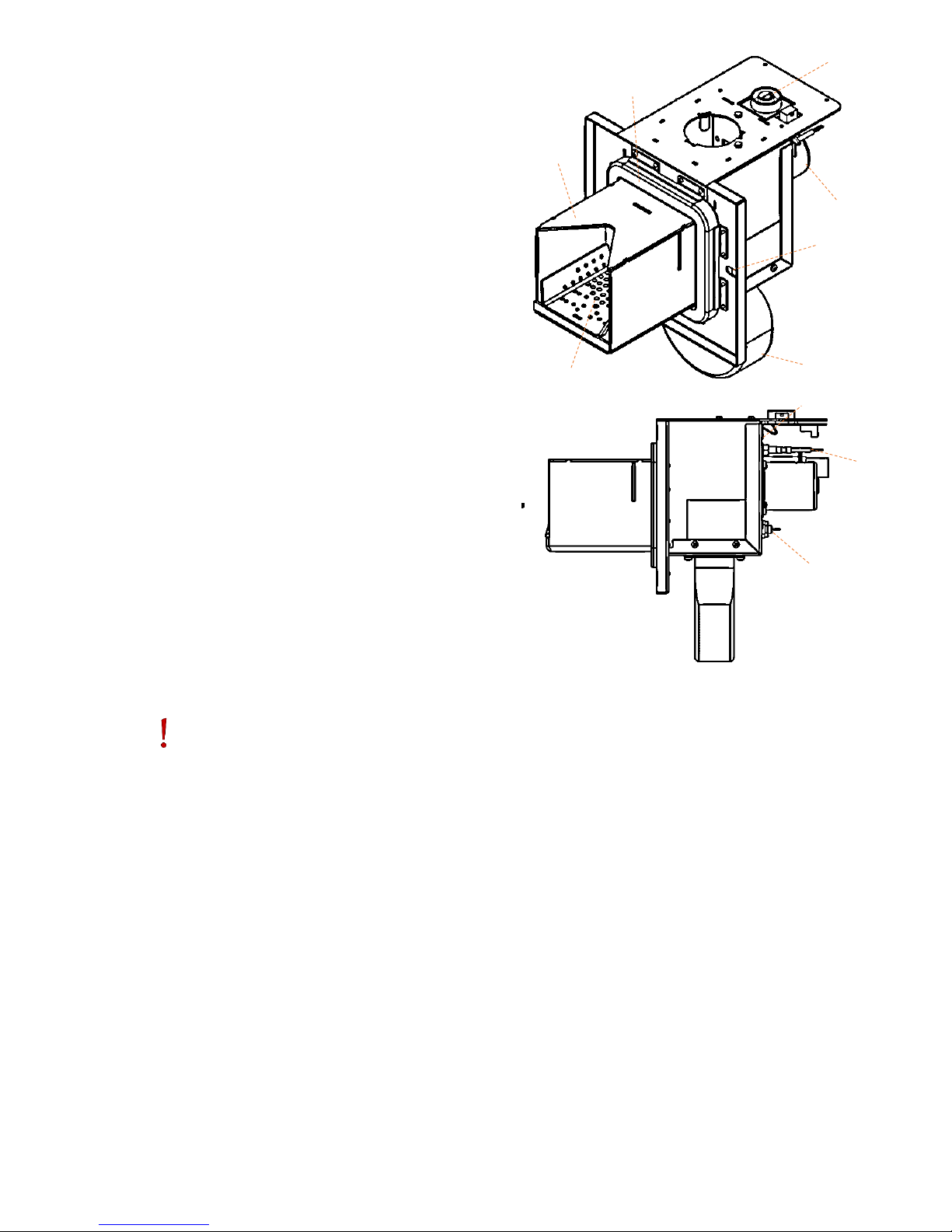
4.1. Biopel 10 - 40kW
You can find 3 doors on the boiler. Two doors on the top of the boiler, one door in the bottom front part of the boiler. There
is top lid on the top of the boiler for better isolation, which decreases the temperature loss. Cleaning doors on the top of
the boiler are removable to get inside the heat exchanger easily, to clean the inside of the boiler without problem.
On each side there is place for pellet burner, covered on one side by metal flap. So you can choose from which side you
insert pellet burner into the boiler. There is also attachement of motor for exchanger cleaning on the sides of the boiler and
also connecting holes for control unit holder attachemen if you use boiler with external type of pellet tank.
Pellet burner can be installed on the right or left side of the boiler body.
There are 2 inlets for temperature sensors on the back side of the boiler. Sink for CH and Termik temperature sensor is
attached on the outcomming water outlet on the top back side of the boiler. On the bottom ack side of the boiler is inlet for
incoming water from heating system into the boiler. Next to this inlet is filling valve outlet to fill up boiler with system
water. There are two covers on the back side of the boiler. First is placed next to the chimney flue path outlet, which covers
lambda sensor and chimney temperature sensor connection. Second cover is at the bottom back side of the boiler for
automatic ash removal motor (additional device). Chimney flue path outlet is positioned on the back side of the boiler as
well. Temperature sensors (CH, termik and Chimney flue gas) re connected on the back side of the boiler. There are shafts
for cables on the sides of the boiler.
On the bottom of the boiler there are adjustable legs, which can change the hight of the boiler to keep it at horizontal level
all the time. Hinges of the bottom front door are removable to make the opening of these dors on left or right side.
Hinges of the bottom front doors are removable. You can install them on the other
side and make to opening of the doors from other side.
There is ashtray inside the boiler and above there are turbulators inserted inside heat exchanger. The reason is to keep the
the heated air inside the boiler as long as possible, to inscrease boiler efficiency. Turbulators can be removed to access th e
heat exchanger easily and clean efficiently all the surface inside the boiler.
a) Top lid, under combustion and cleaning top
doors
b) Sidded bottom ash doors
c) Adjustable legs on bolts
d) Burner blanking flap on both sides of the
boiler
e) Blanking flap of aut. Exchanger cleaning
f) External control unit holder (only with
external pellet tank version)
g) Inlet for CH and termik temperature sensors
h) Inlet for for filling / drain valve and for return
water into the boiler
i) Blanking flap for lambda sensor connection
and chimney temperature sensor.
j) Blanking flap for aut. ash removal system
k) Hinges of top lid
l) Closing handle for ash door
a
b c d
e f g
h
ch
i j k
l
Page 10
Package content:
There are additional accessories inserted with mounting material inside the ashtray. Remove it for completing the
installation. Amount and types of additional parts can vary depending on the type of the boiler.
3pcs of cleaning tools (brush, brush handle,
scraper) – for cleaning the internal parts of
the boiler.
Filling valve – for filling water inside the boiler
and drainig if necessary.
2pcs of burner screws – installed on the
burner outlet to hold the burner at right
position.
Ash container – in the bottom part of the
boiler
Burner flange (for 20, 30 and 40kW boiler) –
installed on the boiler opening for the burner
attachement.
4 screws of the burner flange (for boilers 30
and 40kW) - for mounting flange on the boiler
opening for the burner attachement. Flange
for 20kW boiler is attached directly on the
burner screws.
2 pieces of wing nuts for burner attachement -
to ensure the tightness between the flange
and the burner. Mounted on the burner
screws.
2 washers – placed on the burner screws,
under the wing nuts.
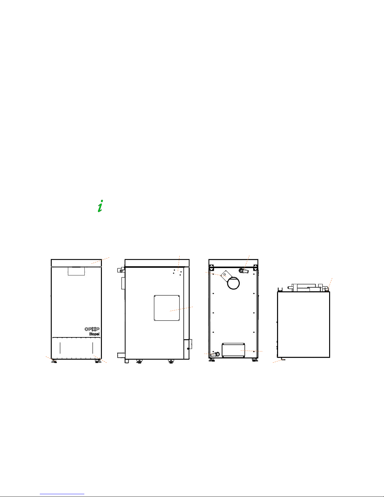
4.2. Biopel 60 - 80kW
The boiler is equipped with three doors. Stoking, cleaning and ash doors. The top of the boiler is, for better insulation, fitted
with a lid. Stoking and cleaning doors are fixed by wing nuts. Cleaning doors are also completely removable. On the sides,
see the burner openings (left and right) and mounting for the control unit.
Installation is possible only with an external type of pellet hopper.
You see two main pipes in the rear part of the boiler. In the upper part of the back side of the boiler is outlet for
outcomming water from the boiler, fitted with two sensors – CH and Termik. In the bottom rear part of the boiler is inlet for
incoming water to the boiler, fittet with filling valve. Flue outlet and opening for the ash removal system (optional, only for
10-60kW) are also located in the rear side of the boiler.
a) Top lid, underneath stoking and cleaning
doors
b) Ash door
c) Boiler legs
d) Burner opennings on both sides
e) Mounting for the control unit
f) Outlet for outcomming water from the boiler,
fitted with two sensors – CH and Termik
g) Inlet for incoming water to the boiler, fittet
with filling valve
h) Connection of Lambda probe and the flue gas
temperature sensor
i) Opening for the ash removal system
j) Upper lid hinges
k) Ashtray door handle
a
b
c
d
e
f
g
h
i jk
Page 11

Package content:
There are additional accessories inserted with mounting material inside the ashtray. Remove it for completing the
installation. Amount and types of additional parts can vary depending on the type of the boiler.
3pcs of cleaning tools (brush, brush handle,
scraper) – for cleaning the internal parts of
the boiler.
Filling valve – for filling water inside the boiler
and drainig if necessary.
2pcs of burner screws – installed on the
burner outlet to hold the burner at right
position.
Ash container – in the bottom part of the
boiler. There could be one or two section
ashtray.
Burner flange – installed on the boiler opening
for the burner attachement.
Burner flange gasket - installed between the
burner opening on the boiler and burner
flange.
4 screws of the burner flange - for mounting
flange on the boiler opening for the burner
attachement.
2 pieces of wing nuts for burner attachement -
to ensure the tightness between the flange
and the burner. Mounted on the burner
screws.
2 washers – placed on the burner screws,
under the wing nuts.
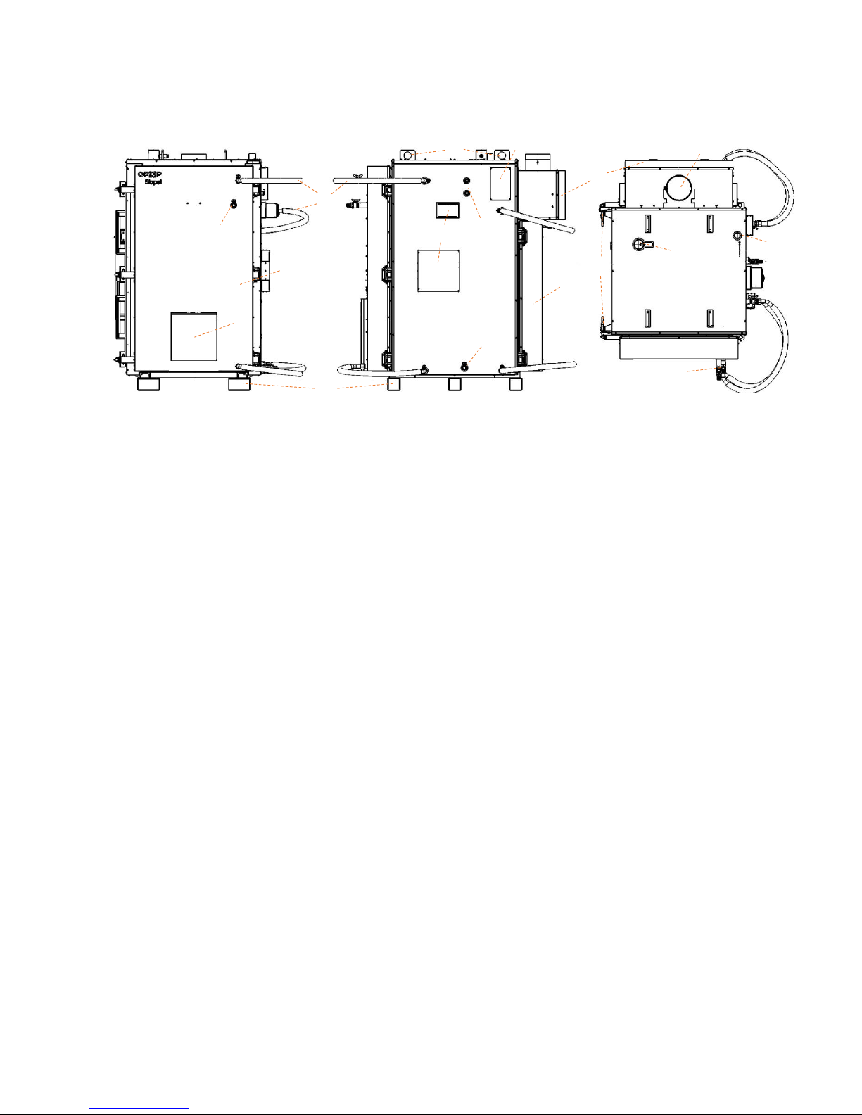
4.3. Biopel 100 - 200kW
These boilers include a two-tier heat exchanger located in the upper part of the boiler. Exchanger pipes are located in a
horizontal position above the opening for the burner installation. Exchanger tubes have 2 diameter sizes for better air flow
in the boiler. In each of the tubes are turbulators, which are designed to reduce the temperature in the flue path so that the
resulting boiler efficiency is maximized. Turbulators are removable for easier access to the heat exchanger during cleaning.
For cleaning of heat exchanger tubes use the handle and plug brush, with which you can clean each of the exchanger tubes.
Be sure to place the turbulators back into each of the tubes after cleaning. The purity of the heat exchanger is critical to
ensure maximal heat transfer from the heated air into the water in the boiler and heating system.
Biopel 100 to 200 kW is equipped with two horizontal multilevel tube heat exchanger.
Biopel 100-200 kW is equipped with two main doors, front and rear. Pellet burner is attached in to the opening which is on
the front doors. Burner flange is attached to this opening as well. The burner is fitted into the hole with two burner screws
and two wing nuts. Proper tightness is important for preventing leackage of air in the boiler or to prevent leackage of fumes
from the boiler out. The door can be opened together with the burner for inspecting the inner parts of the boiler and burner
grate without having to remove the burner of the boiler. To open the door with the burner you must dismantle the PVC
hose between the burner and the feeder so that the external feeder doesn’t stay in the way of door opening.
Caution: Never open the front door with a burner when the flame is in the boiler. For the
flame inspection use always rear door.
Front and rear doors are attached to the boiler using solid hinges and on the other side by closing handles. The tightness of
the closure can be adjusted. Ensure tight closing of both doors and the correct adjustment of closing handles to prevent
accidental opening of the door or leakage of smoke into the room through leaky doors closing. The front and rear doors are
filled with flowing heating system water. Water is pumped through the door through the cooling hoses. Each hose is fitted
with a ball valve. Doors can be separated from system water in the body of the boiler, if need of doors removal, repair etc.
In the upper part of the boiler are water inlet and outlet for connection of the boiler into the heating system. Smaller is inlet
water to the boiler, bigger is outlet water from the boiler. Furthermore, the upper section provides outlet for flue gases.
You can find an opening for connecting the Lambda sensor (optional) on the flue gas outlet.
Boiler handling is provided in two ways, either by increased base in the bottom of the boiler,
or using a hoks in the upper part of the boiler.
Inlet for filling valve is located on the side of the boiler, bottom part. When filling the boiler, chack that all connections are
sealed properly so water cannot leak out of the connections anywhere on the boiler. Especially check cooling hoses
connections and do not forget to open all ball valves on each cooling hose so water can flow inside and outside the frontal
and rear doors.
Electrical parts are installed in the front of the boiler (control unit v9 and connection board). There are also two outlets for
temperature sensor installation (CH and Termik sensor) on the side of the boiler. All cables must be positioned so nothing
can damage cables during operation of the boiler or when opening front or rear doors. It is also important that cables
doesn’t touch metal surface of boiler body (surface under the boiler covers) and that cables do not lay down on the ground
without fixing. Hot ash can permanently damage electrical cabeling. Make sure that cables are fixed on the position and
cannot fall or move into the boiler when doors are opened. Bottom of the boiler is shaped so you can clean inside of the
boiler easily. Use cleaning tools to remove all ash out of the bottom surface of the boiler. Clean all parts of the boiler
Page 12
regularly and check ash content each day during first two weeks of operation. Quality of pellets directly influences how
often you need to clean inside of the boiler (to clean heat exchanger, inside bottom of the boiler, flue path and burner). Set
for your self how often is necessary to clean all mentioned parts according the real pellet consumption and ash creation
during first two weeks of operation. Each boiler room is different. Check chapter Cleaning for more information about
proper way of maintenance.
a) Frontal door
b) Burner opening
c) Cooling hoses with ball valves
d) Automatic exchanger cleaning
e) Bottom support for boiler handling
f) Top support for boiler handling
g) Inlets for CH and Termik temperature sensors
h) V9 control unit and connection board
placement
i) Lambda controller placement (accessories).
j) Rear door
k) Cleaning door for flue outlet cleaning with
ashtray inside
l) Filling valve inlet
m) Flue gas outlet
n) CH water inlet
o) CH water outlet
p) Adjustable door closing mechanism
q) Ball valves for each of cooling hoses
Package content:
You can find following parts for boiler and burner installation inside the boiler. Content can vary considering exact boiler
and burner size. Use thise accessories for completing the installation and move on to the next chapter to start boiler
properly.
3pc cleaning tools (brush, handle, scraper).
Filling valve – for filling boiler with central
heating water.
2pcs of burner screws – installed on the
burner outlet to hold the burner at right
position.
Příruba hořáku – instaluje se na otvor hořáku.
Burner flange – installed on the boiler opening
for the burner attachement.
4 screws of the burner flange - for mounting
flange on the boiler opening for the burner
attachement.
2 pieces of wing nuts for burner attachement -
to ensure the tightness between the flange
and the burner. Mounted on the burner
screws.
2 washers – placed on the burner screws,
under the wing nuts.
a b c
d e f g h i j
k
l
m
n o p
k
Page 13
4.4. Burner
Pellet burner sizes vary from 10 to 200kW, each burner is
different size. The difference between burners is not only the
dimensions, but also different electrical components, grates, etc.
Maximal burner power determinates also the external
dimensions of each burner. Burner is attache by following
components:
a) internal pellet feeder (motor and spiral),
b) fan,
c) ignitor,
d) fotosenzor,
e) safety burner temperature sensor is indicating actual
burner temperature,
f) burner printed circuit board (burner PCB),
g) removable grate,
h) grenamatová plate (30-200kW),
i) sealig cord,
j) openings for burner screws attachement.
Burner pipe is connected on the top of the boiler and fixed by
two small screws. There is also a sealing circle between the
burner pipe and the burner. Two socets for control unit
connection are located also on the top of the burner. Smaller
socet is transferring signal of safety temperature sensor and
fotosensor. Bigger socket is for 230V power supply of all main
electrical components on the burner (fan, motor and ignitor). Fan
and motor is also connected to the capacitors which are
responsible for smooth start of each of the components. Both
condensators are attached on the burner.
Burner body and grate are stainless steel, so they can resist high
temperatures inside the boiler reaching 1100°C. Burner grate can
be removed for proper cleaning. Holes inside the grate should be
always clean for best combustion quality.
Ignitor and sealing cord are consumable parts and must be changed in regular intervals.
Ignitor provides automatic ignition, which takes from 3 to 5min. When flame is created, fotosensor detects light of the
flame and boiler stansfers operation from ignition to PID work. Fotosensor together with safety burner temperature sensor
are responsible for shutting down the boiler when burner temperature is higher than 60°C (safety temp. sensor is
responsible) or when there is no flame inside the boiler (fotosensor is responsible).
Sealing cord must lay on the burner flange all around its surface, so no heat escapes from the burner outside. There is a high
risk of damage when burner is not connected properly. Check the connection always, when burner was removed for
cleaning or other service.
Burner is hearth of heating system and it needs proper regular maintenance. Pay high coution when you clean the grate and
make sure that position of grate is as it should be. More information about cleaning and grate position is written in chapter
Regular maintenance.
Package content:
Burner 10 – 200kW
Burner cover
Burner pipe
2ks screws 4M, for burner pipe fixing
Sealing circuit – for sealing the connection
between burner and burner pipe.
PVC hose – connect feeder and brner pipe
Control unit v9 – attached on the side of the
boiler oron the top of the compact hopper.
2ks wing nuts – for fixing the burner
2ks washers for burner screws
f
i a b d c
e
g
h
j
Page 14
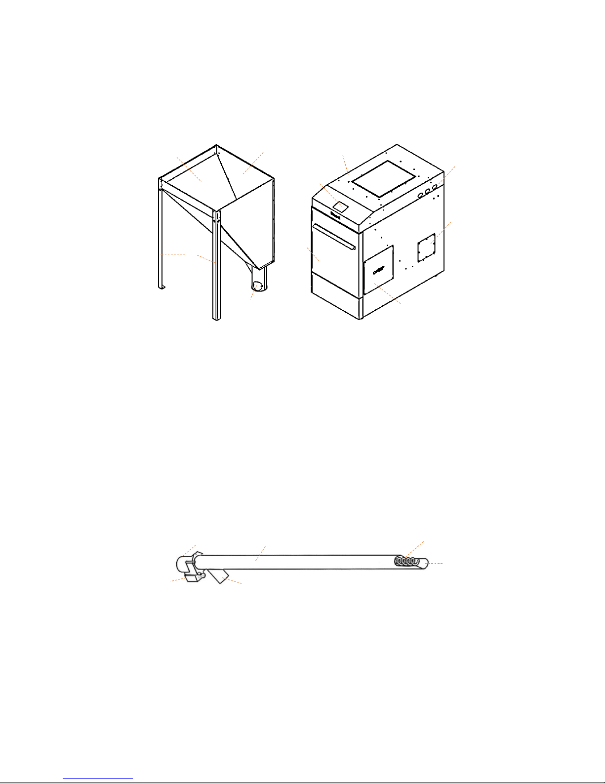
4.5. Pellet hopper
Two types of pellet hoppers are sown below. External and Compact versions. Compact hopper can be used with Biopel 1040kW, External hopper can be used with all Biopel boilers. External hopper is assembled during boiler installation; Compact
hopper is assembled in OPOP. Read chapter Installation process to se how to assemble External hopper properly.
Compact version is on the right side of the picture, all electrical components, including buner are hidden inside Compact
hopper. External hopper is on the left side of thi piture and is used only with 2 or 3m External feeders.
a) External hopper
b) 3 legs
c) External feeder connection into the hopper
d) Clening hole fro removing dust out of the
hopper
e) Filling openening – can be attached by cover
f) Compact hopper
g) Front door
h) Cleaning hole for removing the dust out of the
hopper
i) Cable shaft for electrical wiriing
j) Control unit v9
k) Opening for burner installation on both sides
4.6. External feeder
External feeder is used to transfer pellets from external hopper into the burner. It is used only with externl hopper.
Compact hopper already has external feeder inside. External feeder is defferent type for each boiler power. Check the
sticker on the external feeder to see, if it is the right speed for your boiler power. Use only external feeders for proper type
of boiler.
a) Motor with capacitor – iger boiler you have,
faster feeder you use
b) PVC pipe
c) Feeder spiral
d) Pellet inlet into the feeder
e) Pellet outlet to the burner
f) 230V socket – or electrical connection
a
f
c
d
e g h
i
j
k
a b c d e
f
Page 15

5. INSTALTION PROCESS
Instalation process varies considering the boiler size, pellet hopper type. You can see full installation explanation down below.
Choose your type of boiler and pellet hoper and read all information carefully.
Full installation process can be devidet to following sections:
1. Boiler, burner, hopper, and external feeder installation (chapters 5.1 to 5.6)
2. Accessoriess installation (chapter 5.7)
3. First start (chapter 8)
4. Combustion adjustment (chapters 9.1 to 9.3)
5. Accessories operational values adjustment (chapter 7)
Basic installation type can be devided by the type of pellet hopper. Basic component configuration varies by used pellet hopper.
You can see first type of installation with compact pellet hopper. You can find burner, external feeder and control unit inside the
tank when installation is finished. Picture below is also presented with additional accessories for better illustration of all
possibilities which goes with Biopel boiler.
Biopel set with compact version of pellet hopper
a) Compact pellet hopper
b) Front door
c) Filling opening
d) Acuum transport (accessories)
e) Burner opening from both sides (burner is
inside the hopper)
f) Ash removal system (accessories)
g) Control unit v9
h) Cleaning hole for removing the dast out of the
hopper.
i) Shafts for electrical cables.
j) Connection board for accessories connection
is behind the front cover.
k) Biopel 10 – 40kW
Compact hopper is not connected to the boiler by any means. It is placed next to the boiler and can be moved easily any time.
When hopper is placed to the final position, next step is to attach urner inside the hopper. Open the front doors first. Hold the
front doors and move them up by 2cm first. Than pull back to remove the door completly.
You can connect burner from left or right side of the boiler. Choos the opening on the same side of the hopper as on the boiler.
Opening inside the hopper must be positioned roperly on the burner opening to connect burner easily. Control unit v9 is placed
on the top of tha hopper and connected by cable to the connection board in the front wall of the boiler. Connect this cable into
the connection board into the socket which is on the left side of the connection board. Use small oval openings which are on
both sides of pellet hopper to move the gable from control unit to the connction board.
All cables connected into the connection boards can be holded on the position by two fixing straps abowe the connection board.
a
b
c
d
e f g
h i k
Page 16

There is exteral feeder inside the pellet hoper. Its outlet must be attached by PVC hose to connect external feeder and burner
pipe. Connect cable into the External feeder socket for power supply.
Caution: PVC hose must be installed in a way that pellets fall down to the burner without any problem.
Otherwise you risk damage and back flame inside the hopper.
There is cable shaft on both top sides of the hopper to move cables from the front to the back side of the installation set. Cover
which protects the cables inside the hopper can be removed for easier cble installation. Cover must be placed back to cover
electrical wiring against dust inside the hopper.
Second hopper version is external. External hopper can be used with all Biopel boilers from 10 to 200kW. However you have to
use this type of hopper with Biopel 60 – 200kW always. You can see boiler with external hopper in the picture below. Presented
set is also combined with additional accessories for better imagination what are the possibilities for biopel boilers.
Biopel set with external version of pellet hopper
a) External hopper
b) Filling opening
c) External feeder connetion to the hopper
d) Cleaning hole for dust removing out of the
hopper
e) External feeder (2 or 3m), 50° angle.
f) Ash removal (accessories)
g) Control unit v9
h) Pellet burner
i) PVC hose
j) Burner pipe
k) Compressor cleaning (accessories)
l) Connection board behind thefront cofer of the
boiler
m) Biopel 10 – 200kW
External hopper is assembled during boiler installation. It is ussualy delivered disassembled in one box. External feeder is moved
into the bottom leg of the hopper and fixed by chain to the top edge of the hopper. Check the angle of external feedr from the
ground, which should be 50°. External feeder is connected to the burner with help of PVC hose. PVC hose must be straight so
pellets cn fall down easily to the burner. Connect power supply cable from connection board into the external feeder socket.
External hopper can be placed anywhere inside the boiler room, but you need to achhhive non problem pellet supply from the
hopper to the burner. Check all connection, proper PVC hose installation and make sure that PVC hose doesn’t fall off the feeder
or that PVC hose doesn’t change its shape after some time.
External feeder motor has differen speeds considering feeder type. For each burner power we have different feeder (motor)
speed. Use only the external feeder which is for the same power as your boiler is.
a
b
c
d
f g h
i j k
l
m
e
Page 17

5.1. Biopel 10 – 80kW
This is step by step explanation how to install all biopel boilers from 10 to 80kW of power. Read all information careffuly and
continue chronologicaly, so all important steps during boiler installation are met.
1. Open the covers and remove boiler from plastic protection. During boiler manipulation keep in mind thet boiler has
electronics inside. Make sure that:
a. PIf you moow boiler with wooden protection, make sure that boiler cavers are not damaged by wood or
other parts of wooden covering. There are spikes inside the wood, so be carefull to not damge the boiler
during transportation.
b. Place boiler on strait floor with no deformation. Boiler must be placed horisontaly, no angle is possible.
c. Make sure that there is enough space around boiler and hopper so you can move around the installation
without problem.
d. Check if there is enough space to fully open ash doors and to remove ashtray out from the biler without
problem.
We recommend remove front boiler cover before any manipulation. Cover is not attaced on the
boiler with screws, it only hengs on the screws so be sure you do not damage this cover during boiler
transportation.
2. Remove all accessories out of the boier. Cleaning tools are inside the boiler, connection material is in the
ashtray.
3. Install filling valve on the outlet located in the back bottom side of the boiler.
4. Connect water outlet G1 1/4" to the heating system.
5. Connect water inlet G1 1/4" to the heating system.
6. Connect flue gas outlet to the chimney. Connection must be tight so no smoke escapes out of the flue pipe. Make
sure that:
a. Chimney connection cannot decrease chimney draft below the minimal level mentionad in chapter Main
parameters.
b. Chimney flue path diameter cannot by smaller than flue outlet on the back side of the boiler, so 130 or
178mm, depending on boiler type. Check mentioned value in chapter Main parameters.
c. Connection between flue outlet and flue pipe cannot hide lambda and chimney temperature sensors,
located inside flue outlet on the back side of the boiler.
d. When connection into the chimney is finished, check and measure chimney draft to make sure that
requirement for minimal chimney draft is met. If not we strictly recommend to install Chimney fan which is
optional device to boost natural chimney draft.
Good chimney draft is very important for good combustion, proper ash creation and for smoke
leackage prevention. If you see smoke leackage during operation, chimney draft is too low.
7. Connect water hose on the fillig valve and fill the boiler and full heating system with water. Ceck the maximal
pressure, whch should not increase abowe 2 bars during operation. So pressure should be lower when boiler is not
active and system water is cold.
8. When boiler is filled, close the filling valve and remove water hose.
9. Check tightnes of all pipe connections. If you detect some water leaking, epair it immediately, before you start the
boiler.
10. Check proper position of both CH and Termik temperature sensors, which are inside the sink on the water outlet.
Make sure thay are fixed properly and there is no possibility for the sensors to fall of the sink.
11. Check inside of the boiler, mainly. Proper turbulators positioning inside heat exchanger, chack burner flap below the
stocking doors and chack that there is no accessories left inside the boiler. Remove all parts which should not be
inside the boiler during operation.
12. Check tightnes of all doors. Thay can be damaged during boiler transportation. Sealing cords inside the doors must
tuch the boiler body all around properly, without any holes.
13. Choose the side wher burner will be installed, left or right. On the other side should be burner cover, to close the
opening for burner, if burner is connected from othe side.
14. Proceed to the next chapter if all mentioned steps are done. Next chapter is about pellet hopper and burner
installation. Read all information careffuly to connect both parts properly.
Page 18

5.2. Biopel 100 – 200kW
This is the installation procedure of Biopel boilers with outputs from 100 to 200 kW. The points below serve as a guide for
installing the boiler to the heating system. Individual points are listed chronologically. Read therefore the points
chronologically so you do not forget any of the fundamental points of the installation.
1. Unpack the boiler out of a paper protection. Remove transparent foil and place the body of the boiler to its final
position in the boiler room. When handling the boiler consider following precautions:
a. When handling, be careful about the casing and other components of the boiler. The boiler can be moved
only when the front and rear doors of the boiler are closed.
b. To manipulate boiler body use the trolley positioned under boiler, or crane with a chain attached from the
top of the boiler. Boiler must be always in horizontal position during the transport procedure.
c. Place boiler on strait floor with no deformation. Boiler must be placed horisontaly, no angle is possible.
d. Make sure that there is enough space around boiler and hopper so you can move around the installation
without problem.
e. Check if there is enough space to fully open front and rear doors and to remove ashtray out from the biler
without problem (some boilers are not sold with ashtray).
2. Remove all accessories out of the boier. Cleaning tools are inside the boiler, connection material is in the
ashtray.
3. Install the filling valve on the inlet at the bottom side of the boiler.
4. According to the size of the boiler, filling valve is mounted on the lower side of the boiler, or placed as an accessory
inside the boiler.
5. Connect water outlet G1 1/2" to the heating system.
6. Connect water inlet G1 1/2" to the heating system.
7. Connect flue gas outlet to the chimney. Connection must be tight so no smoke escapes out of the flue pipe. Make
sure that:
a. Chimney connection cannot decrease chimney draft below the minimal level mentionad in chapter Main
parameters.
b. Chimney flue path diameter cannot by smaller than flue outlet on the back side of the boiler, so 199mm.
Check mentioned value in chapter Main parameters.
c. Connection between flue outlet and flue pipe cannot hide lambda and chimney temperature sensors,
located inside flue outlet on the back side of the boiler.
d. When connection into the chimney is finished, check and measure chimney draft to make sure that
requirement for minimal chimney draft is met. If not we strictly recommend to install Chimney fan which is
optional device to boost natural chimney draft.
8. Install the cooling hoses with ball valves on the sleeves on the side of the boiler and on the front and rear doors. For
clarity of colling hoses connections, use image of Biopel 100 - 200kW in chapter Basic componnents of biopel
installation.
Caution: Ball Valves on each cooling hose must be set to open position. Otherwise you
risk overheating.
9. Connect water hose on the fillig valve and fill the boiler and full heating system with water. Ceck the maximal
pressure, whch should not increase abowe 2 bars during operation. So pressure should be lower when boiler is not
active and system water is cold.
10. When boiler is filled, close the filling valve and remove water hose.
Check tightness of all connections. Possible leackage must be repaired immediately
or before boiler start up.
11. Check the inside of the boiler, in particular: proper placement of turbulators in the heat exchanger, the correct
position of the ashtray in the cleaning space (below the flue outlet) and make sure that there are no accessories or
fasteners left inside the boiler.
12. Remove any parts that do not belong to the boiler.
13. Check the front and rear doors of the boiler. Check the correct settings of all closing handles, or adjust the position
of hooks of closing handles that doors are tightly connected to the boiler body when closed.
14. If all points are met, you can proceed to hopper and burner installation.
Page 19
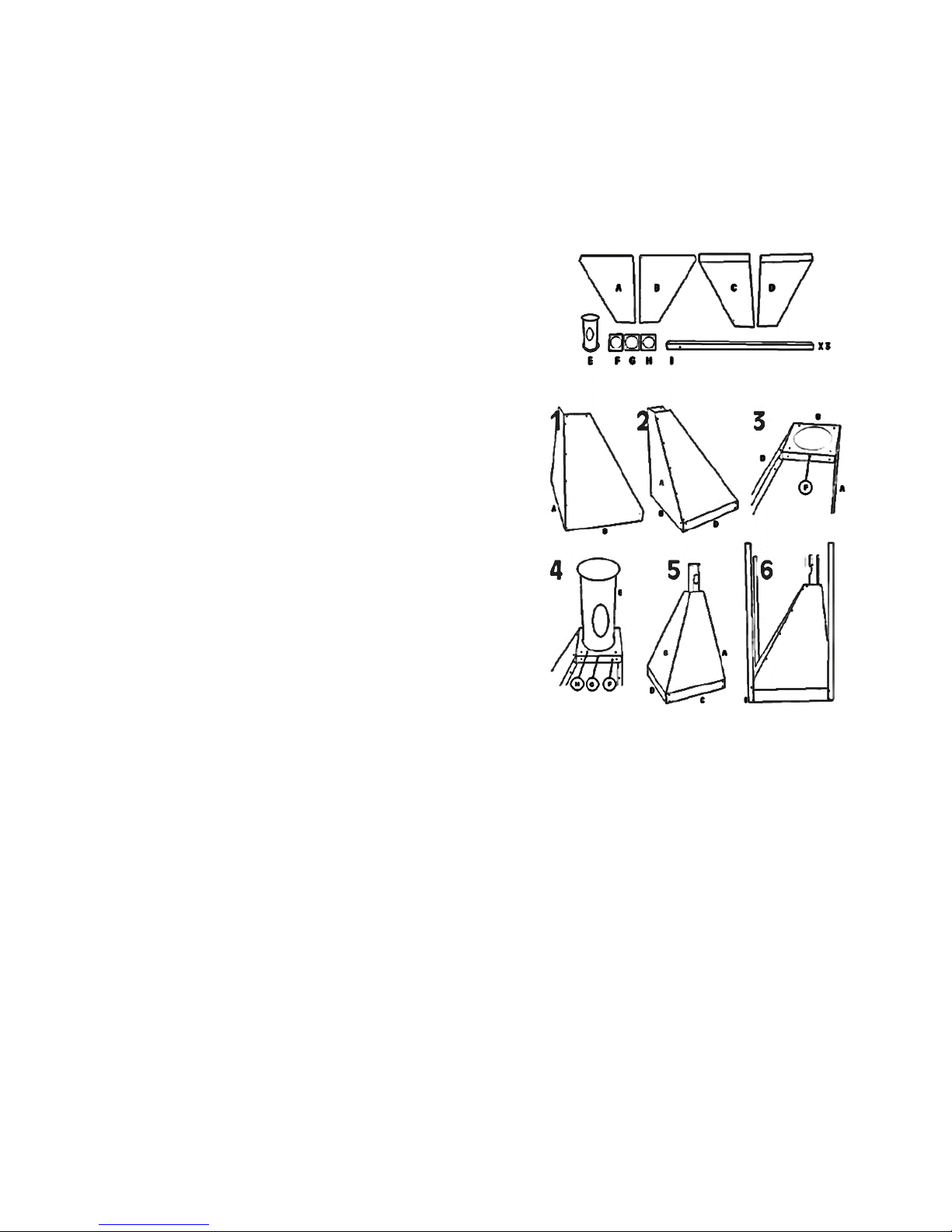
5.3. Pellet tank
The compact pellet hopper installation is very simple since it comes from the factory already assembled. So unpack the
hopper of the wooden cover, remove the foil and put the compact hoper in place next to the boiler side, where the burner
will be assembled. Revmove the burner opening cover form the boiler if necessary to install the burner, but do not forget to
pot this cover on the opposite side of the boiler to close the second burner opening (on the other side of burner position).
Be carefull during hopper transportation, wooden cover is attached with spikes which can damage the hopper surface. We
recommend to remove the cover first and than move he hopper. External hopper is assembled on the site, inside the boiler
room. It comes disassembled from the OPOP factory. You can see installation procedure down below. Follow these steps
carefully.
1. A and B connect together. You have part AB after
connection.
2. Connect D with AB part. You have ABD part after
connection.
3. Connect F with ABD part. You have ABDF part after
connection.
4. Connect parts H, G, E a F with part ABDF.
5. Than, connect C with remaining hopper body.
6. Connect 3 legs onto the hopper body.
7. You are done. Move the hopper on the final position,
next to the boiler and you are reddy to connect external
feeder.
If you are assembling 350kg external hopper, use additional plate
(B type) to extend the standard 220kg hoper. So the installation
procedure is the same as mentioned above only with one
additional B type plate.
Check inside space in the hopper to make sure, there are no
remaining parts, which should not be there during operation.
Leave hopper empty so nothing other than pellets gets to the
external feeder. Next step is burner installation. Read all steps to
attach burner on the boiler body properly.
5.4. Burner
Type and burner size always vary depending the boiler size and power. Burner installation is therefore different considering
the type of boiler and burner you use. Use this explanation as a general manual how to install burner the correct way. Full
brner installation is devided to following steps:
1. Unpack all parts of the burner package out of the box.
2. Install the burner flange on the burner opening on the boiler (left or right side of the boiler), if the burner fange is
part of the delivery (some boiler sizes doesn’t use burner flange and burner is installed directly on the burner
opening on the boiler body. Flange type varies according to the size of the burner and therefore the method of
installation on the boiler is also different:
a. Biopel 10-15kW: no burner flange
b. Biopel 20kW: flange is attached to the 2pc burner screws.
c. Biopel 30-80kW: flange is installed using 4 screws M5, burner package includes frame sealing for the flange.
d. Biopel 100kW: flange is attached to the 2pc burner screws.
e. Biopel 150-200kW: no burner flange
3. Burner must be attached on 2pc burner screws, which should be mounted on the burner flange or directly on the
burner opening on the boiler body (depends on mentioned boiler types above). Tighten this connection by 2pc wing
nuts to make sure, that there is no space between the boiler and burner, so no air can leak out of this connection.
Check the burner few times so it doesn’t move whan you push it up and down and tighten the wing nuts once again.
4. Done. If you moved the hopepr during burner installation, make sure that the pellet hoper is on its final position
befor you fill the hopper with pellets. Next step is External feeder installation, if you use Biopel with external
hopper.
Page 20

5.5. External feeder
External feeder installation must be done only if you use external hopper with your Biopel boiler. If this is your case follow
explanation below to make sure feeder is installed properly. If you use compact hopper, skip this chapter and move to
electrical connectition of external feeder and other electrical components.
1. Remove the paper cover from the top of the external feeder.
2. Make sure that there is no damage of feeder spiral or of PVC tupe inlet, where pellets go to the feeder. If there is
wissible deformation of PVC tupe inlet, there is a risk that spiral get stucked by damaged or angled feeder inlet. In
this case we do not recommend to install feeder with any wissible damage.
3. Move the bottom leg of external hopper towards the burner so external feeder inlet can fit inside.
4. Move the external feeder inlet inside the hopper leg opening.
5. Top part of the feeder should be attached onto the top edge of external hopper by chain. Use small holes inside
hopper legs to hang the feeder in right position.
6. Adjust chain lengt to make sure that external feeder is in 50° angle from the ground.If angle is smaller, feeder gives
more pellets and the opposite. So if the angle is different, make sure you do proper combustion adjustment,
describet in chapter Combustion adjustment.
Caution: Combustion adjustment must be done always, when external feeder angle is not 50°.
Smaller angle means more pellets inside the burner – Fitters menu, Coefficients – make proper
flame adjustment to correct the combustion!
External feeder is on the place. Now you need to connect this feeder to the burner. Folw steps below.
1. Put burner pipe inside the burner top outlet. Do not forget to place sealing circle between the bourner and burner
pipe.
2. Fix this connection by 2pc bolts so the connection is tight.
3. Use PVC hose to establish connection between burner pipe and external feeder. You can cut the PVC hose to the
length you need to make sure, that pallets can fall down to the burner without stucking inside the PVC hose.
5.6. Control unit v9 and connection board
External feeder is connected to the burner. No we need to connect all cables to supper 230V to all electrical components.
Following steps describes electrical wiring and control unit installation.
1. Remove front boiler cover. It hangs on two screws so move cover up by 2cm and tan push towards you to remove
the cover out of the boiler.
2. In case of compact tank, remove small cover on the side of the compact tank (side where burner and boiler is
placed). You will use this opening to move cables from the connection board into the hopper.
3. Connect 230V AC power cord into the power supply socket.
4. Connect 230V AC power cord into the External feeder socket.
5. Connect burner cable into the burner sockets (2 sockets, small and bigger).
6. Connect control unit v9 into the connection board. There is a socket for this on the left top side of connection board.
Place control unit v9 on the position (on the compact tank, or mount it on the side of biopel boiler if you use
external hopper version.
Basic electrical connection is finished. If you plan to connect additional devices into the connection board, use cable safts on
the sides of the boiler to move cables from connection board to the back side of the boiler.
Boiler cannot be in operation if any doors are opened. There is a risk that heet coming out of
the opened door damages electrical wiring around the connection board. Make sure that
cables do not touch hot surface of the boiler.
Electrical connection for all additional devices can be finded in next chapter. Now ther is a time to connect all accessories
which will be used with the boiler. When alla electrical componnents installed, pust ON button (red button on the conection
board), close the connection board and put the front boiler cover back on its place on the boiler.
Before first start, read chapters Electrical connections and Control unit v9. This helps you to better understand control unit
and the way how boiler is operated. These chapters will help you to understand all features of v9 control unit you will be able
to navigate easily through the first boiler start up. First start should be the next chapter you should read to setup the boiler
operation properly. Keep in mind that all the setup can by changed any time inside the menu structure of V9 control unit.
Page 21

5.7. Electrical connections
Internet connection with
RJ45 cable
RS bus outputs for
accessories connection
(lambda, RT10, 431N,
cascade, exhaust fan)
Additonal sensor 4
United output for C4,C3
Additonal sensor 3
Additonal sensor 2
United output for C2,C1
Additonal sensor 1
Solar contact
Room thermostat 2
United output Room reg.1,2
Room thermostat 1
External (weather) sensor
Unitted uotput for weather and
return temp. sensors
Return water sensor
Valve sensor 2
Valve sensor 1
United output for Valve 1,2 sensors
DHW sensor
Chimney temp. sensor
Safety sensor Termik
CH sensor
Internal feeder temp. sensor (burner)
Fotosenzor (fire sensor)
United output for burner and fire
sensors
Vacuum transport
Compressor 1
Compressor 2
Voltage free output
Exchanger cleaning
Deashing
Heater
Feeder 1
Fan
Feeder 2
DHW pump
CH pump
Valve 1 pump
Aditional pump
Valve 2 pump
Valve 2
Valve 1
Page 22

This is the list of all functions inside the control unit which are connected with each electrical output. Use this list for better
orientation of accessories setup and activation. And also in case of alarm message, you can find easily which output is
responsippel for each alarm. It is simple to fid the source of alarm with help of this list, for example when some temperature
sensor is not connected but function inside the control unit connected ith this sensor has been activated.
RJR5 – Fitters menu:
Internet module
RS1 and 2 – Fitters menu:
Lambda
Room thermostat
Additional valve 1 and 2
GSM module
Cascade.
Additional sensor 4 and 3 – Fitters menu:
For possible future use
Additional sensor 2 and 1 - Fitters menu:
Additional pump
Buffer tank
Build in valve 1,2 – Select CH sensor type
Solar contact – Fitters menu:
Solar.
Room thermostat 1 and 2 – Fitters menu:
Room regulator – Regulator standard 1 and 2
Build in valve 1,2 – Room regulator – Regulator standard.
External (weather) sensor – Fitters menu:
Built in valve 1 and 2 – Weather regulation
Weather sensor calibration
Firing up locked
Return water sensor – Fitters menu:
Build in valve 1,2 – Return protection
Valve sensor 2 and 1 – Fitters menu:
Build in valve 1 a 2
DHW sensor – Main settings:
Working modes – Water heater priority, Parallel pumps or Summer mode.
– Service menu:
Dizinfection – Dizinfection temperature
Priority temperature
DHW hysteresis
Chimney sensor – Service menu:
Max. temp. exhaust
Safety sensor Termik – no associated function
CH sensor – Main settings:
CH temperature
CH boiler weekly control
Working modes – House heating
– Fitters menu:
Build-in valve 1,2 – Boiler protection
– Service menu:
CH pump emergency activation
Boiler alarm temperature
Pump switch on temperature
Min. boiler temperature
Boiler hysteresis
Internal feeder temperature sensor – Service menu:
Feeder alarm temperature
Fotosenzor – Service menu:
Pellet settings – Ignition parameters – Firing-up brightness
Pellet settings – Operation parameters – Operation controll
Page 23

Mixing valve 2 and 1 – Fitters manu:
Build-in valve 1,2
Additional pump – Fitters menu:
Additional pump
– Service menu:
Pump switch on temperature
Valve pump 2 and 1 – Fitters menu:
Build-in valve 1,2 – Valve pump 1,2
DHW pump – Main settings:
Working modes – Water heater priority, Parallel pumps or Summer mode.
– Service menu:
Pump switch on temperature
DHW hysteresis
CH pump – Main settings:
Working modes – Water heater priority, Parallel pumps or Summer mode.
– Service menu:
Pump switch on temperature
Internal (burner) feeder – Service menu:
Internal feeder coefficient
Pellet settings – Ignition parameters – Feeder operations and Feeding pauses
Pellet settings – Damping parameters – Feed time and Feed interval
External (tank) feeder – Service menu:
Pellet settings – Ignition parameters – Underpoor time
Pellet settings – Operation parameters – Min. power – Feeder operations and Feeding pauses
Pellet settings – Operation parameters – Max. power – Feeder operations and Feeding pauses
– Fitters menu:
Coefficients – Min and Max feeder coefficients
Fan – Main settings:
Burner cleaning
– Service menu:
Pellet settings – Ignition parameters – Blow out time, Blow out gear, Fan rotations 1,2, Fan delay
Pellet settings – Operation parameters – Min. power – Min. working fan
Pellet settings – Operation parameters – Max. power – Max. working fan
Pellet settings – Operation parameters – Cleaning period
Pellet settings – Damping parameters – Fan rotations
– Fitters menu:
Coefficients – Min and Max fan coefficients
Ignitor – Service menu:
Pellet settings – Ignition parameters – Heater protection and Minimum heater power
Freely programmable output – no associated function
Exchanger cleaning – (Fitters menu) – Exchanger cleaning
Ash removal – (Fitters menu) – Ash removal
Vacuum transport – (Fitters menu) – Vacuum
Compressor 2 and 1 – (Fitters menu) – Compressor 1, 2
Page 24

6. CONTROL UNIT v9
Control unit v9 is high resolution touch screen device. Type of the screen is properly selected in consideratio n of boiler room
environment. It is covered by pelxi glass shield which protects it against dust and scrathes. Conntrol unit is connected into the
connection board in fornt of the boiler by small plug and lay cable. Instalation takes just few seconds. After boiler activation, by
pushing main switch on the side of connection board, is v9 controller switched on and first procedure it takes is to check
firmware versions of v9 controller and external board. Firmware verisons are displayed below OPOP loge when you switch your
boiler on. Tjose numbers should be the same for prober boiler operation.
Next step is to select your language. To do so, click on Menu button, and than navigate yourselve to the right by clicking on right
arrow key to display Language selection. Click on this button and select your language version. Translantion is changed instantly.
We recommend to read carefully next chapters to understand better the way how boiler and control unit v9 operates.
6.1. Basic navigation
Basic navigation is simple mainle because of touch screen, which simplifies usage of this controller. Read basic controller and
Main screen description down below.
Main panel of v9 controller
a) Boiler temperature measured by CH sensor which
is connected into the sink on the water outlet in
the back of the boiler.
b) Selected boiler temperature. Can be changed in
Main settings, CH temperature. We recommend
to set this temperature in range from 65 to 80°C.
c) Real time operation state – Ignition, PID work or
Extinction are the main fases of operation.
d) Actual power in kW
e) Pellet supply correction, made in Fitters menu,
Coefficients.
f) Burner temperature, inside the external feeder.
Which should be from 15 to 55°C during PID
work.
g) Pannel showing component real time operation,
such as fan, feeders, ignitors, pumps and
activated accessories.
h) DHW temperature measured by DHW sensor,
which is connected into the “DHW sens” output
inside the connection board.
i) Selected domestic hot water temperature. Can
be changed in Main settings, DHW temperature.
Works only when one of the DHW modes is
activated in Main settings, Working modes.
j) Display of pump operational modes. Can be
changed in Main settings, Working modes. This
is basically which of CH and DHW pumps has
prority to start to operate first. Read Control
unit’s layout structure for more information.
k) Weather sensor temperature. Sensor is
connected into the „Weather sens.“ output
inside the connection board.
l) Chimney temperature sensor. Should be in
range from 70 to 110°C, by the size of the boiler.
m) Flame detection by fotosensor. If you see this
icon, flame is detected inside the boiler.
n) Room regulator indication, if activated in Fitters
menu, Room regulator.
o) Real time and date.
p) Menu button to access menu layout structure.
q) Change main panel layout to display variety of
information on the main panel. The possibilities
vary depending on the number of accessories
connected into the connection board. So you
can display basic information about each
accessory on the main panel.
a b c d e f g h i j k l m n o
p
q
Page 25

6.2. Main operation modes
Biopel during its operation changes its fases according to request from user or automatic modulation. Each operation mode
is displayed on the main screen. You can find more information about each operation mode down below, including sub
steps made by control unit duringeach mode of operation.
Ignition: automatic ignition of pellets layed on the grate. Maximum time for ignition is set to 12min. Boiler goes trough
several stages during this operational mode:
Preventilation – grate cleaning by a fan, factory settings (hereinafter referred to as FS) = 30s.
Underpoor time – pellet dosing by feeders, the internal feeder in the burner operates twice as long as external
feeder to move all of the pellets to the burner grate. FS = 12 – 15s
Fan delay – preheating ignitor before starting the fan. FS = 30s
Fan speed 1 – the fan speed during the first 6 minutes of ignition. The fan operates at low speed, to produce a
flame, while not cooling down the ignitor. FS: 3-8%.
Fan speed 2 - the fan speed during the second 6 min ignition. Maximum ignition cycle is 12 min. If pellets are not
ignited within first 6min of ignition, fan will increase its speed to create a flame. The standard ignition time is 3-6
min. FS: 5-16%.
Firiing up delay – flame was created, fotosensor detects light, followed by stabilization of the flame procedure. If
the flame detection by fotosensor is stable, boiler goes into PID work (normal operation). If the detection by
fotosensor is not good and stable, boiler remains at the stage of Ignition, until the flame is not large enough. If the
flame is not stable enough, it is followed by the second ignition (at least 12 additional minutes).
The output of the phase Ignition may be:
o Moving on to the PID work - normal operation of the boiler, or
o The alarm message – Failed ignition, pellets failed for some reason to ignite. Boiler performes 2 tries of
ignition before the announcement of this error condition appears. For more information, see chapter
Operating and error messages.
Caution: the indicated time intervals and other values are set at the factory. But they may be
changed in Service menu anytime.
PID work: normal operation of the boiler, indicated by current boiler power output and fan speed in %, which correspond
to a percentage of current power in kW. The PID works following operating states are listed below:
Min power – boiler starts its operation in the lower half of the power spectrum, from 0 to 50% of maximum power.
The reason is to not damage small flame by incomming pelelts after ignition. FS = 1-50% of maximal power, by the
size of the boiler.
Max power – burner is slowly increasing its power up to the maximal 100%. This can take from 5 to 15min.
depending on burner size. Power modulation is influenced only by set and measured CH temperature.
PID modulation – When measured Ch temperature is close enough to the set CH temperature, burner starts to
modulate power down to keep the CH temperature at level approximately +-5°C. Set CH temperature can be
overreached by 5°C, which is value set in Service manu, Supervission temperature. If CH temperature is higher for
more than 5°C than desired CH temperature, boiler is turned off – extinction pahse.
The output of the phase PID work may be:
o Transition to Extinction – set CH temperature is +5°C or higher than set CH temperature.
o Continuose PID work – set CH temperature is not overreached more than 5°C because of PID modulation.
Buner will keep the flame inside and maintain CH temperature on levels around desired CH temperature.
Power modulation will go up and down in time to keep the CH temperature at set level.
o Off by room thermostat – room regulator can turn off the boiler any time, which causes boiler to go to
Extinction phase. Desired room temperature has been reached.
Extinction: if measured CH temperature is higher than 5°C than set CH temperature, boiler goes to Extinction phase. Room
regulator can force boiler to go Extinction as well when set room temperature has been reached. Boiler goes through
following stages in Extinction phase:
Cleaning – when there is still flame inside, fan speed is at 70% and external feeder is stoopped to burne remaining
pellets inside the burner.
Cooling – when there is no flame inside, fan speed is 100% for several more minutes to clean the burner.
When Extinction is finished, a „Stand by“ message appears. When CH temperature drops by
15°C or when room regulator sends signal to heat – ignition phase is activated again.
Page 26

7. CONTROL UNIT’S MENU LAYOUT
You can find full explanation of all functions inside v9 control unit. This list can be used as a general description for each feature
to clearly understand how each feature works and which functions are connected between each other. Use this list in case,
when you do not understand proper feature function. Keep I mind, that there is also full function description directly inside the
control unit menu stricture. Just hit “i” icon next to each function to display full description directly inside v9 controller.
7.1. First start
This is the first and most important setup, which has to be done immediately after activating the boiler for the first time.
Only certified plumber can access this menu to setup all important parameters of boiler and its componnents. There is ful
chater about First start. Read this chapter for more information on this topic.
7.2. Ignition / Extinction
These functions are responsible for manual start and stop of the boiler. You will see here Ignition, when boiler is deactivated
and you will see here Extinction, when boiler is in operation. By pussing this button, you activate or deactivate the boiler.
Keep in mind that you cannot force the boiler to stop or start, if room thermostat is connected and activated. Room
thermostat has alwas priority, so you start and stop the boiler by changing required room temperature on the room
thermostat directly.
7.3. Main settings
Content inside this setup is ment for final customer to change basic values without influencing critical parameters of
combustion and safety features. However we advise you to change these values only when you are sure what will be the
result of each change. Ask for advice before changing any value you do not understand properly.
1. CH temperature
This option is used for setting the CH (central heating) boiler temperature. Recomended
value is range from 60 - 80°C. Highre the temperature is, better for boiler life and good
operation.
60–80°C
2. DHW temperature
Select desired DHW (domestic hot water) temperature. DHW heating is activated only if
DHW temperature sensor is connected and Working mode in Main settings is properly
selected.
45–70°C
3. Burner cleaning
Activation of burner fan for cleaning. Burner fan increases its speed in periodes to clean
the grate. This cleaning is semi automatic. Keep in mind that manual cleaning of burner
is always required.
3.1 Cleaning period
How often fan increases it's speed to clean the grate. Bigger burner / more frequent
cleaning necessary.
6-15min
3.2 Fan operation time
How long fan cleans. Bigger burner / longer time necessary.
10-20s
3.3 Blow force
Speed of the fan during cleaning. Recommended values: 50-100%. Bigger burner / faster
speed necessary. Be careful about high burner speeds during cleaning interval. High
speed (especialy during minimum power) can cause extinction (no flame after cleaning).
High fan speed can also cause unburned pellets to fall down to the ashtray. Adjust fan
speed if you see situations like this.
50-
100%.
4. Working modes
Set operation mode of CH (boiler pump) and DHW (hot water production pump) pumps. Caution:
pumps are activated only when measured CH temperature is higher than 40°C, which is set in
Service menu, Pump switch on temperature.
When heating DHW, DHW pump is started only when measured CH temperature is higher than
measured DHW temperature, so DHW tank is not cooled down by colder CH temperature.
Pumps operation is indicated by icon on main panel.
4.1 House heating *1
Only CH pump is active when CH temperature is higher than 40°C. No DHW production.
4.2 Water heater
priority*2
DHW pump is prior to CH pump. When set DHW temperature is reached - DHW pump is deactivated
and CH pump starts to heat up the house. When measured DHW temperature drops below DHW
hysteresis - CH pump is deactivated and DHW pump starts to operate until set DHW temperature is
reached again..
When heating DHW, DHW pump is started only when measured CH temperature is higher than
measured DHW temperature, so DHW tank is not cooled down by colder CH temperature.
Page 27

4.3 Parallel pumps *2
Both CH and DHW pumps work in the same time to heat up DHW tank and house as well. Pumps
are activated only when measured CH temperature is higher than 40°C, which is set in Service
menu, Pump switch on temperature.
4.4 Summer mode *2
Only DHW ump operates. CH pump is off constantly. If you use electric valve to heat up DHW tank
instead of pump, you can activate CH pump during summer mode by Main settings, Working
modes, CH pump summer.
4.5 CH pump summer
CH pump can be activated during Summer mode if electric valve has been used instead of regular
DHW pump. In this case you have to maintain water flow during DHW production by CH pump.
*1 Connect CH pump into the „CH pump“ output in connction board.
*2 Connect DHW pump into the „DHW pump“ output in connection board.
5. Tray filled
When activated, indicator of fuel level is set to 100% (visible on the main screen view). This
indicates that pellet tank has been refilled. Important: to enable this feature, calibrate fuel
consumption in Fitters menu, Tank calibration.
6. CH boiler weekly
control
The weekly regulation enables programming of ste CH temperature changes, each hour during the
day and for each week day separately.
6.1 Mode 1 (MIN-SUN)
Activation of mode 1.
6.2 Mode 2 (MON-FRI)
(SAT-SUN)
Activation of mode 2.
6.3 Set mode 1
Select desired CH temperatures for mode 1.
6.4 Set mode 2
Select desired CH temperatures for mode 2.
7. Alarm history
Operation history, all boiler states and alarm situations are saved in this list.
8. Disinfection
Thermal desimfection applies to the DHW production and can be activated only i situation when
DHW production is activated in Operation modes in Main settings. Thermal disinfection involves
increasing the DHW temperature to necessary disinfection temperature (min. 60°C) throughout the
entire DHW circulation.
You can change parameters of Disinfection in Service menu, Disinfection.
9.1 Screen settings
Change all possible settings of how the main touch display behaves. You can change brightness,
screen fade pahe for lower power consumption, etc.
9.2 Screen view
Select one of two types of man screen view.
9.2.1 Panel view
Display main user information on main screen.
9.2.1.1 Manufacturers
screen
Display service live parameters on main screen. Password required.
Only for installers and advanced users.
9.2.1.2 Screen brighness
Change screen brightness when screen is active.
9.3 Screen fade
When screen is not used for 2min (value set in Screen view, “Damping time” feature), it goes to the
low energy consumption state. Select the screen brightness for this state of function.
9.4 Damping time
How long it takes for the controller to proceed to the “Screen fade” state of operation (when
nobody is using the controller).
9.5 Sound of the alarm
Activate and deactivate sound during the alarm situation.
9.6 Sound of the buttons
Activate or deactivate sound of buttons during controller's screen ussage.
9.7 Software update
Firmware update procedure is mentioned in chapter Firmware update.
10. Factory settings
Reset all values in Main settings to the factory preset values.
11. Software version
Current program version. Module version - firmware inside main Connection board, Screen version -
v9 touch controller firmware version.
Firmware update procedure is mentioned in chapter Firmware update.
Page 28

7.4. Fitters menu
You can activate and adjust all accessories connected into the connection board. You can also adjust combustion settings
for minimal and maximal burner power. Only installers and advanced users can change these values.
1. Cascade *
Cascade controller is additional device which allows you to operate up to 4 boilers as it would be
only one big boiler and use power of each boiler only when needed.
1.1 Weather control
Cascade operation is based on outside weather sensor. You can select from which outside
temperature level your boilers starts to operate.
1.1.1 Ekvitermní regulace
Boilers are activated by external weather temperature. Lower the temperature is, more boilers will
be in operation and the opposite.
1.1.2 Modulation
Cascade controller operates the boiler to achieve selected boiler temperature.
1.2 Number of boilers
Select number of boilers connected into the Cascade controller.
1.3 Hysteresis
Hysteresis is the boiler temperature drop when boiler should be started again. If boiler achieves its
maximal CH temperature, it waits set temperature drop befre it starts to operate again.
1.4 Lower limit
Minimal boiler CH temperature. If temperature is not reached during the time set in “Waiting time”
submenu, next boiler is activated.
1.5 Boiler 3 switch-on
temperature
Works with Modulation mode. CH temperature when selected boiler should be started.
1.6 Boiler 2 switch-on
temperature
Works with Modulation mode. CH temperature when selected boiler should be started.
1.7 Boiler 1 switch-on
temperature
Works with Modulation mode. CH temperature when selected boiler should be started.
1.8 Waiting time
Select time how long it takes to start second/third/ forth boiler if CH temperature is not reached
during selected period of time.
1.9 Version
Actual firmware version of cascade controller.
* Connect Cascade module into one of two RS outputs inside connection board.
2. Exhaust fan *
Select exhaust fan operation speed for min amd max burner power. Exhaust fan modulates its
speed acording the burner power and helps to boost up chimney draft. Fan speed modulation is
automatic, inside the range you select.
2.1 Min working fan
Min speed of exhaust fan during minimal burner power.
2.2 Max working fan
Max speed of exhaust fan during minimal burner power.
2.3 Version
Actual firmware version of exhaust fan controller.
* Connect Exhaust module into one of two RS outputs inside connection board
3. Coefficients
This feature allows you to correct combustion by changing fan speed and external feeder operating
time. Use (+) and (-) to increase or reduce fan speed and external feeder run time for minimal and
maximal burner power separately.
3.1 Max. fan coefficient
Correct fan speed for maximal power (100% of burner power). We recomend to do this correction
when real burner power is at 100%.
3.2 Min. fan coefficient
Correct fan speed for minimal power (1% of burner power). We recomend to do this correction
when real burner power is close to 1%.
3.3. Forced minimal
power
By activating you force burner to operate only at minimal power. Use this function to adjust
minimal flame size and quality of combustion. Do not forget to deactivate this feature when you
finish minimal flame power correction.
3.3 Min. feeder coeficient
Correct feeder operation time during minimum burner power. We recomend to change it only if
you see that the flame after ignition or when power is modulated down is too big or too small.
3.4 Max. feeder
coefficient
Correct feeder operation time during maximum burner power. We recomend to change it when
burner operates at 100% of its power.
Page 29

4. Manual mode
Start manualy all electrical components to check proper function. Boiler will be turned off, it it is in
operation phase.
5. Lambda *
To regulate combustion by measuring remaining oxygen inside the boiler.
5.1 First of time update
Set the time of first oxygen correction. It takes some time for flame to stabilize itself
after ignition so it is necesary to wait aproximatly 5min and than make first correction.
5min.
5.2 Time of update
How often lambda corrects the flame. This value should be around 5min. Bigger the
burner size is the bigger the update time must be.
3-5min.
5.3 Oxygen surge
% of feeder operating time correction. This correction will aply each update time you
have set in “Time of regular update” function.
2%
5.4 Fan stroke
% of fan operating speed correction. This correction will aply each update time you have
set in “Time of regular update” function.
2%
5.5 Sum
When deactivated - Feeder and Fan corrections will be still the same (no increase or
decrease after time). When activated - Feeder and Fan corrections will be +100% each
“Time of regular update” until it reaches Min and Max correction which is the limit.
Yes
5.6 Min. correction
This is the minimal limit when Feeder and Fan corrections can go if “Sum” function is
active.
There is a risk, that lambda ensor will decrease boiler power if this value is too big. If
this is the case and corrected flame by lambda sensor is small, you need to change this
number closer to 0%.
-10%
5.7 Max correction
This is the maximum limit when Feeder and Fan corrections can go if “Sum” function is
active.
If flame is too smoky, black smoke coming out of the chmney, the % f correction is too
big and lambda is forcing to supply too many pellets inside the burner. If this is the case,
change this number closer to 0%. You have to chack the lambda oxygen detection. If
there is high level ov oxygen inside the boiler during long period of time, there is some
leackage on the boiler body where secondary air goes inside and increases oxygen level
inside the boiler. Check tightness of all doors and connections on the boiler.
+10%
5.8 Lambda 100%
Excess oxygen measured by lambda sensor during maximal burner power.
Lambda sensor is able do measure remaining (not burned) oxygen inside the boiler in
range of +-1%. Short period peaks in oxygen measurement are normal, because of
dosage of new pelelts, chimney draft or because of burner cleaning by fan.
By the
size of
the
burner
5.9 Lambda 1%
Excess oxygen measured by lambda sensor during minimal burner power.
Lambda sensor is able do measure remaining (not burned) oxygen inside the boiler in
range of +-1%. Short period peaks in oxygen measurement are normal, because of
dosage of new pelelts, chimney draft or because of burner cleaning by fan.
By the
size of
the
burner
* Connect Lambda module into one of two RS outputs inside connection board.
6. External sensor
correction*
Correct external sensor measurement. Cable lenght can influence measured
temperature value.
Outside tempareture is measured by Weather sensor and displayed on the main screen
next to icon. T is used with Valve’s weather operation features or with cascade
controller.
6.1 Correction value
Correct value to set proper temperature matching the real external temperature. Cable
lenght can influence measured temperature value.
6.2 Averaging time
Time of averaging all measured values when external sensor activated. This allows
eliminating short peaks in outside temperature measurement, which can appear de to
the outside weather conditions – wind, rain, sun, etc.
Lower number – more data of outside temperature will be stored inside the memory.
Higher number – the opposite.
30-100s
* Connect external weather sensor into the „External sensor“ output inside connection board.
Page 30

7. Compressor 1, 2 *2
Compressor cleaning of burner or heat exchanger.
Indicated by icon on the main screen.
ON state
Off state
7.1 On
When activated, compressor is cleaning after extinction and during
operation acording the time in “Pause time” submenu.
When you clean during operation, burner looses its flame afte compressor
cleaning, so after 30s with no flame boiler goes to automatic ignition. For
this reason we recommend to clean during operation only with big
powers (80kW or higher) or if boiler is running without reaching set CH
temperature, so it never stops.
On
7.2 Off
When deactivated, compressor is cleaning only after extinction and it
doesn't clean during PID work.
Use this way of cleaning for smaller powers (10-60kW). Compressor will
clean when boiler is stopped by room regulator or when CH temperature
is reached. When extinction phase is completed, compressor starts to
clean acoording to the values set below.
Off
7.3 Cleaning period
Total time of one cleaning period. Ussualy from 1 to 3 min, higher burner
power longer Cleaning period must be. During this period selenoid valve is
opening and closing by set values in “Opening time” and “Cycle time”
submenus.
If Compressor is set to ON, so it cleans also during PID work, we
recommend to select this walue to 1min max. If you have longer
compressor cleaning than that, after 30s boiler goes to automatic ignition,
because there is no flame inside the boiler, but there is stil 30s left for
compressor cleaning – so there is a risk that compressor will blow out all
supplied pelelts for ignition.
1min
3min
7.4 Opening time
“Opening time” of selenoid valve. Valve is opened periodicaly during
“Cleaning period”. Ussualy 1-2s.
2s
2s
7.5 Cycle time
Waiting time for next “Opening time” of selenoid valve. Each cleaning
period the selenoid valbe is opened (Opening time) periodicaly and
“Pause time” is the waiting time for next opening (to pressurize the
compressor again).
25s
20s
7.6 Pause time
Waiting time for another “Cleaning period”. From 10 to 20 hours. This
function works only during PID work, so only if compressor is On.
10-24h
We do
not use
*1
*1 Compressor if set to OFF works only after Extinction (when boiler is turned off). That is why we do not care about Pause time.
*2 Connect solenoid valve into one of two outputs „Compressor 1 or 2“ inside connection board.
8. Vacuum *
Use vacucum transport to transfare pellets form silo to the boiler room.
8.1 Operation time
Set how long vacuum transport works each day. Pellet hopper should be filled during
this time, which ussualy takes 30min to 1h. We recommend to measure how long it
takes to fill up the hopper in your exact situation and select the value acording to that.
30min -
1h
8.2 Switch on time
Set the time when vaccum transport is activated during the day. Vacuum transport will
then work for period of time set in “Operation time” submenu.
30min –
3h
8.3 Switch on time 2
Set the second time when vaccum transport is activated during the day. Use it if you
need to fill up the pellet hopper more than once in a day.
30min –
3h
8.4 Opening time
Set how long it takes to fill up the vaccum container. It is one cycle of vacuum suction. It
mainly depends on the PVC tupe instalation so check by yourselve how long it takes to
fill it completly. It takes aproximatly 80 to 200s.
80-200s
8.5 Pause time
Time when vaccum container flap is opened to relase all pelets from vaccum container.
We recomend to set 20s. Vacuum transort is than activated again and works for period
of time set in “Opening time” submenu.
Electic switch on the vacuum container must be switched on by flap to make this
system work again. If flap stayes opened by the level of pellets inside the hopper,
vacuum transort is deactivated and waits until pellet level drops down so the flap can
close again and electric xontact is switched on again.
20s
* Connect Vaccuum transport into the „Vacuum“ output inside connection board.
Page 31

9. Ash removal *
Removes ash from the boiler to the ash container. Extendes time for manual cleaning.
Indicated by icon on the main screen.
9.1 Operation time
How long is the ash removal motor active. Works periodicly. Number should be set
from 5 to 20 min acordingly to the burner size and number of ashes created. Bigger
burner you have the longer operation time you need to clean all ashes.
5-20min
9.2 Pause time
How long it waits without operatig. It depend on pellet quality and burner size. Number
could be anything from 2 to 20 hours.
2-20h
* Connect Ash removal into the „Deashing“ output inide the connection board.
10. Exchanger cleaning *
Heat exchanger cleaning provided by turbulators inside the boiler.
Indicated by icon on the main screen.
10.1 Operation time
Moves the turbulators inside heat exchanger. Should be from 5 to 15min. Bigger burner
power, longer operation time.
5-10min
10.2 Pause time
Waiting time for next operation. From 10 to 15 hours. Bigger burner power, shorter
operation time.
5-15h
* Connect Het exchanger cleabing into the „Cleaning“ output inside connection board.
11. Room regulator
Select type of room regulator which is connected to the Connection board. Select standard
regulator which works on opened/closed circuit without voltage, or RT10 OPOP regulator.
When room regulator activated, icons indicates current state of operation on the main
screen. When icon is red – room regulator sends signal to not heat. When icon is orange, room
regulator sends dignal to heat.
11.1 Standard room
regulator 1 *1
Open/closed circut typ of thermostat.
11.2 Standard room
regulator 2 *1
Open/closed circut typ of thermostat.
11.3 Regulátor OPOP *2
RT10 room regulator, connected to RS output inside Connection board.
11.4 Firiing up function
When activated – room regulator turns boiler ON or OFF with no delay.
When deactivated – boiler will decrease its CH temperature by number set in “Room reg. temp.
lower” function when there will be no request for heating from room regulator.
11.5 CH pump room
regulator
CH pump is operated by room regulator. If ther is no request for heating, boiler and CH pump is
deactivated.
Always check real influence to the heating system when pump is deactivated to be sure there is not
risk of overheating when CH pump is stopped.
11.6 Room reg. temp.
lower
Boiler CH temperature decrease when room regulator sends signal to stop heating. “Firing up
function” must be activated to use “Room reg. temp. lower” function.
If set CH temp. is 70°C and Room reg. temp. lower is 10°C, boiler will be turned off when measured
CH temperature reaches 70-10 = 60°C.
*1 Thermostat standard 1, 2 connect into the „Room reg 1,2 and Com“ outputs inside connection board.
*2 Regulator OPOP (type RT10) connect into one of two RS data outputs inside connection board.
12. Control from solar
panel*
Connect external device controlling solar panels for boiler activation/deactivation if there is or is not
request for heatin by Biopel boiler. This contact is non voltage, based on closed/opened circuit.
12.1 Control from solar
(NO)
Normal opened contact.
12.2 Control from solar
(NC)
Normal closed contact.
* Connect solar device into the „Solar and Com“ outputs inside connection board.
13.1 Firing up lock *
Select from which outside temperature, measured by outside weather sensor, should boiler start.
13.2 Set temperature
If there is lower outside temperature than set point, boiler will not operate untel the outside
temperature increase above set point.
* Friing up lock works only when external Weather sensor is connected into the „External sens.“ output inside connection board.
Page 32

14. Buffer parameters *
Select the way of buffer tank heat up.
14.1 Buffer
You can activate or deactivate buffer tank heating in this submenu.
14.1.1 Off
Deactivate heating of buffer tank.
14.1.2 On
Activate heating of buffer tank.
14.2 DHW function
Select the type of DHW production if buffer tank is ussed. Selection depends on exact heating
system instalation.
14.2.1 From buffer
DHW production operated by DHW pump and buffer tank. Boiler will not be started, if there is
higher measured temperature inside the buffer tank. So DHW will be heated by buffer tank not by
the boiler. Boiler will not be started if temperature in buffer tank is higher than requested DHW
temperature.
14.2.2 From boiler
DHW production is operated by DHW pump and boiler. Boiler will be started when there will be
request for DHW production.
14.3 Set temp. top
The function enables the user to set the buffer's upper set temperature (the sensor should be
placed at the upper part of the tank). After reaching this value, the pump deactivates (provided that
also the buffer's bottom set temperature is reached).
14.4 Set temp. bottom
The option enables the user to set the buffer's bottom set temperature (the sensor should be
placed to the bottom part of the tank).
* Connect temperature sensors for buffer into the „C4“ and „C3“ outputs inside the connection board.
15. Built in valve 1, 2 *1
Mixing valve operation for one heating circuit.
15.1 Valve OFF
Diactivate valve operation.
15.2 Valve ON
Activate valve operation.
15.3 Set valve
temperature*2
Requiered valve temperature which is going to the heating circuit.
15.4 Calibration
Calibrate the mixing valve if the operation is not as it should be. Movement from
minimum to maximum opening. It is basicly calibration of the maximum range of
motion and it's done automaticly.
15.5 Single stroke
The lenght of one movement of mixing valve. Connected with “Measurement pause”
function.
1-20%
15.6 Min opening
You can select minimum opening to achieve minimum water curculation in heating
circuit. If you want to separate boiler from the heating circuit completely, select 0 in this
function.
0-5%
15.7 Opening time
How long it takes to move the valve from minimum to maximum opening. It also
depends on valve's parameters.
120s
15.8 Measurement pause
Pause between one stroke (movement). Control unit measures temperature periodicaly
and makes the Single stroke action each time you set in this function. Connected with
“Single stroke” function.
30s
15.9 Valve type
By changing valve type, max valve temperature is changed to protect the heating
system against overheating.
15.9.1 Vavlve type CH
valve
Central heating valve. Maximum valve temperature is 85°C.
50-85°C
15.9.2 Floor valve
Floor heating valve. Maximum valve temperature is restricted to 55°C to protect
damage of floor heating pipelines.
10-55°C
15.10 Weather control *4
Valve will be operated by external weather sensor. External sensor must be connected!
15.10.1 Heating curve
Set equithermal operation by selecting heating curve in full range of outside
temperatures. Valve temperature is changed automaticly considering outside weather
temperature. Valve temperature is chenging automatically between these set points.
Page 33

15.11 Room regulator
Room regulator can influence valve operation. Select type of influence in this submenu.
15.11.1 Controll without
room controller
Room regulator is deactivated. Room regulator has no influence to valve operation.
15.11.2 RS regulator
decrease
Room regulator RT10 is lowering valve temperature by set value in “Room reg. temp.
lower”.
15.11.3 RS regulator
proportional
Room regulator RT10 is closing or opening the valve considering actual request for
heating from room regulator.
15.11.4 Standard room
regulator
Activate standard (open/close circuit) room thermostat 1 or 2.
15.11.5 Room reg. temp.
lower
Select temperature by which will be the set valve temperature lowered in case there is
no request for heating from room regulator. It is connected with “Set valve
temperature” and “RS regulator decrease” functions. “RS regulator decrease” feature
must be activated to use this function.
15.11.6 Room
temperature difference
Room temperature hysteresis. By how much must room temperature drop to start
heating angain (opening the valve). Connected with “RS regulator proportional” or
“Standard room regulator” functions. One of these two functions must be activated to
use this feature.
15.11.7 Change in the set
temp.
In case of connection and activation of “Standard room regulator” feature, you can
select the valve temperature dectrease if there is no request for heating. Connected
with “Set valve temperature” and “Standard room regulator” functions.
15.12 Propor. coeff.
How often room regulator checks room and valve temerature nad how often makes
correction of current state to keep valve state in consensus with current setup.
15.13 Opening direction
Direction of valve opening. It depend on the type of the mixing valve you use and on
where you connected both L1 and L2 cables inside the connection board into the “Valve
1” or “Valve 2” outputs.
15.13.1 Left
Mixing valve moves from right to left when opening.
15.13.2 Right
Mixing valve moves from right to left when opening.
15.14 CO sensor selection
Select sensor which works as a CH sensor. Connected with “Boiler protection function”.
Standard setup is “CH sensor” but you can change it in case of some special
installations.
15.14.1 CH sensor
CH (boiler temperature) sensor. It must be connected, or you will get an alarm message.
15.14.2 Additional sensor
1 *6
C1 sensor. Sensor must be connected if you activate it, or you will get an alarm
message.
15.15 Boiler protection
Protect boiler against high CH temperature. Mixing valve will open and valve pump will
push hot water out of the boiler if measured CH temperature is higher than selected
value in “Max temperature” function.
15.15.1 Max temperature
If there is higher temperature than set point, valve opens to push hot water out of the
boiler. Valve pump will operate to push hot water out of the boiler until CH
temperature is lower than set point.
85°C
15.16 Return protection
*3
Use mixing valve as a return water protection to protect boiler against low temperature
limit (risk of condensaion inside the boiler).Return sensor must be connected or you get
alarm message.
15.16.1 Off
Return protection is deactivated. In this case there must be additional valve installed to
protect boiler against low return temperature.
15.216.2 On
Return protection is activated. Valve will be closed until valve temperature is higher
than selected temperature in “Min. return temp.” function. In this case you do not need
to use any oadditional valve to protect boiler against low return water temperature,
because this protection is maintained by mixing valve directly.
15.16.3 Min. return temp.
Set minimum returning temperature to the boiler. Should be from 45 to 65°C. It depend
on the max CH temperature which is going out of the boiler. The difference between CH
and return temperature should be lower than 20°C. Minimal return temperature should
be 50°C.
55°C
Page 34

15.17 Valve pump *5
Valve pump operation can be adjusted in different ways to achieve exact way of
operation you need. Possibilities of how to adjust the valve pump are listed down
below.
15.17.1 Always ON
Valve pump is always activated without stop.
15.17.2 Always OFF
Valve pump is always deactivated
15.17.3 Always above the
treshold
Pump works if valve temperature is above the set point.
15.17.4 Switch on
temperature
Pump works when temperature is at set point or higher.
15.18 Factory settings
Reset to the factory settings. All valve setup will be lost.
*1 Connect Mixing valves 1 or 2 into the „Valve 1“ or „Valve 2“ outputs inside the connection board.
*2 Connect Valve sensors 1 or 2 into the „Val.1 sens.“ or „Val.2 sens.“ outputs inside the connection board.
*3 Connect Return water sensor into the „Return sens.“ output inside the connection board.
*4 Connect Weather sensor into the „External sens.“ output inside the connection board.
*5 Connect Valve pump 1 or 2 into the „Valve 1 pump“ or „Valve 2 pump“ outputs inside the connection board.
*6 Connect Additional sensor into the „C1 and Gnd.“ output inside the connection board.
16. Valve 1, 2 *
Mixing valve operation for one heating circuit with help of external 431N module.
*1 Connect 431N module into one of two RS data outputs inside the connection board.
17. Additional pump *
Activation/deactivation of additional pump.
17.1 Device type
Select type of the pump.
17.1.1 Pump deactivated
Deaktivace přídavného čerpadla.
17.1.2 CH pump
Central heating pump operated by CH temperature sensor and Boiler hysteresis.
17.1.3 DHW pump
Domestic hot water pump operated by DHW temperature sensor and DHW hysteresis.
17.1.4 Circulation pump
Standard heating circuit circulation pump. Temperature can be selected in functions Max
temperature, Min temperature, Sensor selection which operates the pump.
17.1.5 Floor pump
Floor heating pump behaves the same way as Circulation pump with one diference, maximum
temperature of pump activation is decreased to protect floor heating system. Temperature can be
selected in functions Max temperature, Min temperature, Sensor selection which operates the
pump.
17.2 Max temperature
Max temperature in which Circulation or Floor pump is active.
17.3 Min temperature
Min temperature in which Circulation or Floor pump is active.
17.4 Sensor selection
Select senzor which operates Circulation or Floor pump. If you activate sensor which is not
connected to the Connection board in front of the boiler, you get an alarm message.
17.4.1 CH sensor
CH sensor connected into the “CH sensor” output inside the connection board.
17.4.2 DHW sensor
DHW sensor connected into the “DHV sensor” output inside the connection board.
17.4.3 Valve 1 sensor
Valve sensor 1 connected into the “Valve1 sensor” output inside the connection board.
17.4.5 Valve 2 sensor
Valve sensor 1 connected into the “Valve2 sensor” output inside the connection board.
17.4.6 Return sensor
Return water sensor connected into the “Return sensor” output inside the connection board.
17.4.7 Weather sesnor
Outside weather sensor connected into the “Weather sensor” outputs inside the connection board.
17.4.8 Additional sensor 1
Additional sensor 1 connected into the “C1” output inside the connection board.
17.4.9 Additional sensor 2
Additional sensor 2 connected into the “C2” output inside the connection board.
* Connect Additional pump into the „Aditional pump“ output inside the connection board.
Page 35

18. Modul GSM *
GSM module is additional device which allows you to change basic parameters by sms and receive
alarm messages on your mobile phone.
18.1 Vypnutý
Deactivation od GSM module.
18.2 Zapnutý
Activation of GSM module.
* Connect GSM modul into one of two RS data outputs inside the connection board.
19. Ethernet module *
Ethernet module enables remote control by our online serices.
19.1 Off
Ethernet module is offline.
19.2 On
Ethernet module is online.
19.3 Registration
Get registration number to register your boiler online. This number is valid for 2 hours. If you do not
finish registration within this time, you need to get a new number.
19.4 DHCP
The Dynamic Host Configuration Protocol (DHCP) is a standardized network protocol used on
internet protocol (IP) networks for dynamically distributing network configuration parameters, such
as IP adresses for interfaces and services.
19.5 IP address
An Internet Protocol address (IP address) is a numerical label assigned to each device (ethernet
module) participating in a computer network.
19.6 IP mask
A subnetwork, or subnet, is a logical, visible subdivision of an IP network.
19.7 Gateway address
The gateway address (or default gateway) is a router interface connected to the local network that
sends packets out of the local network.
19.8 DNS address
The Domain Name System (DNS) is a hierarchical decentralized naming system for computers.
19.9 MAC address
A media access control address (MAC address), also called physical address, is a unique identifier
assigned to network interfaces for communications on the physical network segment.
19.10 Module version
Ethernet module firmware version.
* Connect connection board with your modem or router by RJ45 ethernet cable.
20. Tank calibration *
Calibrate the indicator of pellet level inside the tank
20.1 Tank full
First fill the tank with the pellets to the top. Then select “Tray full” function. Calibration will be
activated. Wait until all pellets are burned.
20.2 Tank empty
When all pellets are burned select “Tray empty”. Calibration will be deactivated. Now proceed to
the Basic settings and select Tray full always when pellet tank filled up. Indicator on the main screen
shows you 100%.
* After successful calibration go to Main settings and hit “Tray filled” function every time you fill hopper with the pellets. After
pushing this button, you will see 100% indicator on the main screen. If this indicator is not displayed, push left or right arrows at
the bottom of the main screen to dispay this indication.
21. Clock settings *
Change actual time.
22. Date settings *
Change actial date.
* Important for “CH boiler weekly control”, “Alarm history” and online features.
23. Factory settings
Do you want to reset all parameters form Fitters menu back to the factory values?
Page 36

7.5. Service menu
Service menu is used to adjust feeder operation and fan speed during maximal and minimal burner power. This menu is
secured by password to make sure only certified plumber can access critical parameters for proper function of all electrical
components of Biopel boiler. Only certified installer with OPOP permition can change these values.
1. Pellet settings
Change feeder and fan parameters fo min and max burner power for all 3 main
operation phases (ignition, work, extinction).
1.1 Ignition parameters
Change parameters for ignition.
1.1.1 Blow-out time
Cleaning interval before ignition. From 30s to 1 min. This feature is connected with
“Blow by gear” feature.
30s
1.1.2 Blow-by gear
Speed of the cleaning before ignition. This feature is connected with “Blow out time”
feature.
100%
1.1.3 Underpoor time
Dosage of pellets for ignition phase. Ussualy from 12 to 16s. It depends on burner size,
chimney draft and pellet size. More pellets – longer time to create flame. However if
there is not enough pellets (les than 12s), there is a risk of poor flame detection.
12-16s
1.1.4 Firiing-up delay
Delay of feeder operation for ignition. It should be the same as “Blow out time”
function. When fan stops cleaning feeder supplyes pellets on the grate.
30s
1.1.5 Feed time
Internal feeder operation during ignition to supply remaining pellets on the grate during
ignition. Ussualy 3min.
5s
1.1.6 Feed interval
Waiting time of internal feeder during ignition phase.
100300s
1.1.7 Fan rotations
Speed of the fan during first half of ignition phase. Exact speed depends on fan type and
it is from 1 to 8%.
1-8%
1.1.8 Fan rotations 2
Speed 2 of the fan during second half of ignition phase. Exact speed depends on fan
type and it is from 3 to 16%.
3-16%
1.1.9 Heater protection
Maximum ignition time. 12min. Burner tryes to ignite twice. If the ignition process is not
successfull (no flame) for the second time it shows alarm message “Heater error”.
12min
1.1.10 Firing-up
brightness
Sensitivity of fotosensor. Lower number means higher sensitivity. If photosensor sees
the light even if there is no flame inside the boiler - increase the number to decrease
the sensitivity. If photosensor doesn't see the light even if there is flame in the boiler -
decrease the number to increase sensitivity.
You can see real time light measurement on the left bottom corner of the screen. This
number should be from 1000 to 5000 during PID work.
38
1.1.11 Fan delay
Fan operation delay to heat up the igniter. There is 30s waiting time from the ignition
start to heat up igniter. After 30s fan is started.
30s
1.1.12 Minimum heater
power
You can reduce heater power to extend its life. Be aware that low number can cause
longer or not succesfull ignition.
0
1.2 Operation parameters
Change parameters of feeder and fan for PID work, at minimal and maximal power.
Inside this range (min to max power) is fan and feeder operation changed automatically
by PID work.
1.2.1 Min. power
Change fan and external feeder operation during minimum burner power. Keep in mind
that flame must be stable during this stage, so there is no risk of extinction or poor
flame detection. If you make min. power flame too small, Burner cleaning can cause
extinction and forced ignition because of that!
1.2.1.1 Max. feeding
pause
Maximum feeding pause during minimum burner power. Keep in mind that flame must
be big enough so fotosensor can see the light. If the number is too big (long pause
between dosages of pellets at minimal power), there is a risk of poor light detection.
7-25s
1.2.1.2 Min. feeder
operation
Minimum operating time for the external feeder during minimum power of the boiler.
1-3s
1.2.1.3 Min. working fan
Speed of the fan during minimum burner power. If the speed of the fan is too fast at
minimal power, there is a risk that flam ewill be destroyed by to fast fan speed. The
number is ussually close to 20% of fan speed.
5-30%
Page 37

1.2.2 Max. power
Change fan and external feeder operation during maximal burner power. Flame must be
orange, not agressive. Dark, red flame - not enough oxygen (slow fan speed, too many
pellets). Yelow, agressive flame - to much oxygen (fast fan speed, not enough pellets).
1.2.2.1 Max feeder work
Maximum operating time for the external feeder during maximum power of the boiler.
1-8s
1.2.2.2 Min. feeding
pause
Minimum feeding pause for external feeder during maximum burner power.
7-25s
1.2.2.3 Max. working fan
Speed of the fan during maximum burner power.
10-70%
1.2.3 Cleaning period
Forced cleaning of the burner. When time set, boiler will stop operation and force
Extinction phase. When extinction is finished, burner ignites pellets automatically again.
It is good to activate this feature for bigger burners, such as 100-200kW. Recomended
time is 20h.
0-20h
1.2.4 Operation controll
How oftenis the flame detection checked. If there is no light detected by photosensor
during certain period of time, boiler goes from operation to Ignition automaticly.
Standard number is between 20 to 50s.
20-50s
1.3 Damping parameters
Change parameters for extinction.
1.3.1 Fan rotations
Speed of the fan during extinction, to clean and cool down the grate.
50-80%
1.3.2 Feed time
Operation time of internal feeder during extinction to supply all remaining pellets on
the grate.
5s
1.3.3 Feed interval
Pause time of internal feeder.
10-100s
1.3.4 Damping time
Maximum extinction time when there is flame detected by photosensor. If there is no
flame control unit jumps to “Delay time” function to clean the grate.
5-10min
1.3.5 Delay time
This is cleaning and cooling of the grate after flame is gone. This time depends on
burner size. Biger burner you have longer the time must be. From 5 to 15min.
5-15min
2. Max.temp exhaust
Maximum temperature in the chimney flue path. If the temperature is too high, boiler
reacts by decreasing the burner power.
Actual chimney temperature is indicated by icon on the main screen.
Check recomended maximal chimney temperature of your boiler in chapter Main
parameters.
220°C
3. Feeder alarm temp
Maximum temperature inside burner. 60°C set from the factory. If the temperature
inside the burner is higher you get a “Feeder temp. too high” alarm message.
60°C
4. Priority temperature
This is maximal CH temperature when DHW production has been activated in Main
settings, Working modes. To be sure, that hot CH temperature doesn’t flow inside HW
tank it is set, that CH temperature durnig DHW production is max 75°C. When “Prioroity
temperature” (CH temp.) during DHW productiin is reached, boiler is turned off.
75°C
5. CH pump emergency
activation
CH pump is activated during alarm status until CH boiler temperature doesn't drop
below set point.
85°C
6. Pump switch on
temperature
CH boiler temperature when pumps are activated. When CH temperature is lower than
set point, pumps are deactivated to protect boiler against low temperature corrosion
and to save some energy.
40°C
7. Boiler alarm
temperature
Maximum boiler temperature, If the temperature is higher, alarm message “CH
temperature too high” appears. When CH temerature is higher than set point, an “Boiler
overheated” alarm message appears.
93°C
8. Internal feeder
coefficient
Internal feeder works longer time than external feeder. The time extension is set in this
function. Ussualy 100% longer operating time.
100-
200%
9. Fan
Factory setup of the fan. No need to hange this value. For producer only.
10. Min. boiler
temperature
Select minimal CH temperature which will be possible to select in Main settings, “CH
temperature”.
20-45°C
Page 38

11. Growth impulses
Mosfet overheating protection. Factory value is 7. Mosfet is responsible for fan speed
modulation. It can be overheated when for example fan is dirty and its rotation is not as
it should be. This creates higher current in the mosfet and to protect the damage, a
“MOSFET temperature too high” message appears on the screen.
Higher number means faster reaction on mosfet overheating. 0 means this protection is
deactivated. Check proper fan function whne this messige is shown
0-20
12. Supervision
temperature
By how much can be the desired CH temperature overreached before burner goes to
Extinction pahase and is stopped afterwoods. This feature is connected with “CH
temperature” function in Main settings.
Boiler is trying to keep CH temperature in range from desired CH temperature to +5°C
whithout turning off.
When set CH temperature +5°C is reached, boiler goes to Extinction.
5°C
13. Boiler hysteresis
CH temperature minus “Boiler hysteresis” means level of temperature when boiler is
activated again.
CH temperature = 75°C, Boiler hysteresis = 15°C. Boiler will be activated automaticly
again when CH temp. drops below 60°C.
5-15°C
14. DHW hysteresis
DHW temperature minus “DHW hysteresis” means level of temperature when DHW
pump/valve is activated again. DHW temperature 60°C, DHW hysteresis = 10°C. DHW
pump/valve will be activated automaticly again when DHW temp. Drops below 50°C.
5-10°C
15. Disinfection
Forced increase of DHW temperature to disinfect bacterie inside DHW circuit.
15.1 Disinfection
temperature
Select temperature to which boiler increases its level to disinfect DHW heating circuit.
Connected with “Disinfecion time” function.
75°C
15.2 Disinfection time
How long the DHW temperature stays increased.
Connected with “Disinfection temperature” function.
10min
15.3 Max. time of
disimfection heating
Maximal safety time of how long can be DHW temperature increased to selected value
in “Disinfection temperature” function. If during set time is increased DHW temperature
not reached, boiler returns to normal DHW production after finishing the maximal time
of disinfection.
This is a safety feature to make sure, tah DHW temperature doesn’t stay increased for
long period of time.
20min
16. Boiler alarm min
temperture
Minimal CH boiler temperature which should be reached in time interval set in “Alarm
time: temp. does not rise”.
If this CH temperaure is not reached during this time, ther will be an alarm message
“Temperature rise failed” on the main screen.
30°C
17. Alarm time: temp.
does not rise
During this time the minimal CH temperature set in “Boiler alarm min temperture”
function must be reached.
If the CH temperature doesn’t reach selected value within specified time, you get alarm
message “Temperature rise failed”.
This is a boiler protection when for example there are no pellets inside the hopper, or
other possible situations to double secure proper boiler function.
30min
16. Factory settings
Reset of all Service menu parameters to factory settings.
7.6. Language selection
Change language by selecting “Languages” insi emnu layout of v9 controller. Main language is set to Eniglish from the
factory, but you cen change I any time in this sub menu.
Page 39

8. FIRST START
After successful installation of all electrical componnets and accessories there is finaly time to setup the boiler and start it for
the first time. You have to access First start menu to setup boiler properly so all main functions will work according the burner
and boiler power. First start menu is rotected by password so only educated installers can access and setup main boiler features.
Caution: First start must be done when burner is deactivated, in extinction so there is no flame inside.
You anot do First start during ignition or PID work phases properly. In other case, values would not
match your selection in First start menu.
Control unit will ask you step by step about basic informations of the boiler and burner. Wen you finish your selection move to
next question by pushing exit button.
You have 30s for each question. If you don’t make your selection in this time, control unit moves to
another question after 30s of waiting time.
For this reason we recomend to read diagram of First start below first and than do it in real time, so you will be informed about
all the questions before you entre First start and yoou will spent less time thinking about each question. 30s interval is there to
make sure that control unit doesn’t stay in First start if you don’t make any selection.
Use all the information in first start diagram on the next page. This will help you navigate
through the setup easily.
Set actual date and time – important for timer schedule functions, internet connection and also Hystory of operation to see
the alalrm times properly.
Burner power – select your burner size to save all the operational values of feeder and fan into the service menu setup.
Check maximal burner/boiler size on the stickers which are placed on the side of the burner and on the back side of the
boiler. Caution: wrong type of power selection can damage boiler or burner!
Select CH temperature and Hysteresis – Central heating (CH) temperature is outcomming boiler temperature measured by
CH sensor. We recommend to set this temperature in range 65-80°C. Hysteresisi is temperature drop when boiler is started
again. Let say your boiler reached desired CH temperature and stopped. Hysteressis is responsible for repeated start of the
boiler when CH temperature drops by selected value of Hysteresis.
Next is the CH and DHW pumps activation, if connected into the connection board. Connect CH pump into the “CH pump”
output and connect DHW pump into the “DHW pump” output inside the connection board. When DHW pump activated it is
important to connect DHW sensor into the “DHW sens.” output or you get alarm message that sensor is not connected.
Accessories activation in following order:
o Room regulator – standard (non voltage version connectd into the „Room reg.1“ or „Room reg2“ outputs) or RT10
which is OPOP regulator, connected into one of the RS data output inside the connection board.
o Lambda sensor – connected into one of the RS data output inside the connection board.
o Compressor 1,2 – connected into the „Komp1“ or „Komp2“ outputs. There is no difference between Compressor 1
or 2, both have same function. So it doesn’t matter which one you choos to activate.
o Vacuumu transport, Ash removal, Exchanger cleaning, Exhaust fan – these you connect into the „Vacuum“,
„Deashing“, „Cleaning“, “RS” data output.
Mixing valve 1,2 – connect on „Valve1“ or „Valve2“ outputs. Caution: when valves activated, do not forget to connect Valve
1 ot 2 temperature sensors into the „Valve1 sens.“ or „Valve2 sens.“ outputs, otherwise you get alarm message that sensors
are not connected. If you use pumps for heating circuit operated by mixing valve connect each pump into the „Valve1
pump“ or „Valve2 pump“ outputs and activate directly inside Fitters menu, Build-in valve 1 or 2 sub menu.
Next is basic explanation about how to clean the boiler, which components are important for boiler operation and what
customer shold know about the maintenance in general. Installer is responsible to tell these to customer.
At the end of First start you will be ashked to start the boiler for the first time. You can start the boiler manually any time
inside the menu by pushing Ignition button. When started, boiler goes to ignition, which ussualy takes 5min to complete,
than to the PID work. If room regulator has been activated, you have to increase room temperature by room regulator so
boiler starts to operate. Otherwise it will be stopped by room regulator even if you select Ignition in menu layout of v9
control unit.
Keep in mind that most of the setup you do in First start can be changed any time in Fitters menu.
You can change most of the values of Fiist start any time in Main and Fitters menu. Next step (chapter) is about combustion
adjustment, making sure that minimal and maximal flame parameters are correct. Move to the next chapter.
Page 40

Question Your selection options
Page 41

First start setup is finished. If you clicked on yes button, boiler will start automatic ignition phase. You can activate ignition phase
any time in manu layout of v9 controller, by selecting “Ignition”. If room regulator has been connected, make sure it is active
and selected room temperature is higher than real measured room temperature, so room thermostat starts the boiler.
Next step is flame adjustment. Follow describtion in next chapter named Combustion
adjustment for achieving good combustion in minand max burner power.
Page 42

9. COMBUSTION ADJUSTMENT
After Ignition phase activation wait until pellets are ignited automatically and boiler changes its operational status from ignition
to PID work. When there is a flame, boiler modulates power up to the maximum value set in First start settings. Wait until
burner power is at maximum, indicated on the min screen by kW and speed of the fan is Po aktivaci kotle (Roztápění) počkejte,
% also visible on the main screen under fan icon. Now there is time to open top door and look at the flame. Check quality of
combustion and flame parrametrs by desctibtion below. Keep in mind that also quality of pellets, chimney draft, incoming air
inside the boiler room and other external factors influences combustion quality and ash creation. If you use Biopel boiler with
lambda sensor, flame adjustment is automatic after lambda sensor activation.
Keep in mind, that quality of combustion highly depends on pellet quality, proper chimney draft. If these requierements are not
met, combustion quality will drop significantly.
9.1. Flame parameters
Flame type coming from the burner can almost certainly determine whether the combustion process is optimal, or whether
it is necessary to make a correction. Examples of good and bad combustion processes are listed below.
Ideal flame at 100% power:
The maximum length depends on the size of burner (it may be affected also by chimney draft and type of
pellets).
o boiler 10-15kW = about 25-30 cm from the end of the grate
o boiler 20-30kW = about 35-45 cm from the end of the grate
o boiler 40-80kW = about 50-70 cm from the ends of bones
o boiler 100-200kW = approx 80 to 120 cm from the end of the grate
The yellow-orange color of flame, unburned pellets do not fall out of the frate, only soft ash inside ashtray.
Incorrect flame at 100% power:
The maximum length of the flame is less than or greater than dimensions mentioned above.
Flame colour is light yellow (to fast fan speed) or dark orange to red (to slow fan speed).
Unburned pellets fall into the ashtray, dark smoke comes out from the chimney.
Ideal flame at 1% power:
Flame must be big enough, so fotosensor detcts the flame with no problem. To check flame detection look at
the flame icon in top right corner of main screen.
Or you can go to Service menu, Pellet settings, ignition parameters, Firiing up brightnes and check the live
value detected by fotosensor in left bottom corner of the screen. The numbers during min power should be
moving from 500-3000, not lower. If the number is lower, flame is too small or fotosensor is not cleaned.
Incorrect flame at 1% power:
Flame is too small and unstable so fotosenzor doesn’t detect the flame correctly. Increase the flame size by
following parameters.
Use following functions to correct the flame. Whole combustion process can be influenced by fan speed and external feeder
operation and you can do so always for minimal and maximal power separately. Inside this range (from min to max) is fan and
feeder operation corrected automatically by PID work considering measured and selected CH temperature.
9.2. Change fan speed
To change fan speed use “Min. fan coefficient” and “Max. fan coefficient” features in Fitters menu, Coefficients. Use “forced
minimal power” feature to force burner to run constanly at minimal power to adjust min. power flame. Make these
corrections if you see flame with following parametrs:
Decreasing the numbers (minus values):
Flame is too aggressive and creates sparkles
Fan is pushing unburned pellets out of the
grate
Flame is too small and agressive
Increasing the numbers (plus values):
Flame is slow and dark red
There is a lot of dark ash and badly burned pellets
on the grate
Flame is too big and smokes
Page 43

9.3. Change operation time of external feeder
If fan correction is not enough to keep the flame at desired paramaters, use feeder coefficients to change number of pellets
for minimal and maximal power. Go to Fitters menu, Coefficients and use a “Minimal feeder coefficient” and “Maximal
feeder coefficient”. Use “Forced minimal power” feature to force burner to run constanly at minimal power to adjust min.
power flame. Make these corrections if you see flame with following parametrs:
Decreasing the numbers (minus values):
There is too much black ash on the grate
Flame is too big and smokes dark
Chimney temperture is higher than
recommended
Increasing the numbers (plus values):
Boiler is not able to heat to desired CH
tempereture
Flame is too small and aggressive.
Chimney temperature is lower than
recommended.
Wait 5min after each correction and check new flame parametrs after. Each correction takes at least 5min to be visible on
the flame itself. If you are not satisfied, make correction again until min and max flame size is as it should be.
Keep in mind that boiler must run at stable min or max power to really see how the flame looks like at this (min or max)
stage of operation. If CH temperature is not reached, boiler wil, run at maximal 100% of power – this is the time do do max
power flame corrections. To make min power flame corections, use “Forced minimal power” feature in Fitters menu,
Coefficients.
Do not forget to turn off “Forced minimal power” feature when you finish with min flame
corrections. Otherwise boiler will run only at min power.
In case of non standard installation, use following advices to make sure the combustion at min and max power is at it should
be. Follow explanation inside next subsection.
9.4. Non standard installation
You installation should be as close as possible to recommended parameters listed below. These points must be considered
especially in case of external tank usage.
External feeder type (speed of the feeder) for proper boiler size. Each boiler, burner and external feeder is labeled
by sticker. On this sticker you can always see for what power is this componned ment to bee. So if you use external
feeder, check the sticker to be sure you use feeder for proper boiler size. There are several external feeder types
with different motor speed, so make sure you use proper model for your boiler.
External feeder ground angle should be 50°C
Chimney draft should be 15Pa
Pellet size should be 6mm. if you use 8mm pellets make sure you adjust flame parameters for minimal and
maximal burner power as mentioned above.
If one or more of points above are not met, keep in mind you have to do proper flame adjustment as mentioned above to
make sure that:
Flame at maximal power is big enough to give you proper power. Combustion is good enough to cleate soft ash
made by only small perticles. No black smoke is commeng out of the chimney. Flame has yellow to orange color.
Flame at minimal power is stable, so there is no risk of unexpected loss of flame. Fotosensor detects the minimal
power flame properly (flame icon on the main screen is not disepearing).
You can be sure, that boiler operation and combustion is perfect, as it should be, when you follow all steps above. You can use
“Coefficient” features in Fitters menu any time, when you change pellet type or your combustion is not as good as it was at the
beginning. Keep in mind that cleaning of the boiler, burner and flue path is essential for goog combustion.
Speed of ash creation and quality of combustion is highly influenced by pellets and by chimney draft. Low chimney or bad pellets
will increase ash creation, pellets will not be burned properly and you will spend more money because of higher pellet
consumption than is necessary.
Use certified plumber or OPOP staff members to get more details on how to adjust the
flame after commitioning.
Boiler is properly setuped. All necessary procedures are finished. We recommend to reed chapter about boiler and burner
cleaning as a next.
Page 44

10. HEATING SYSTEM EXAMPLES
The most used heating system installations are listed below. This describtion includes full explanation of how to connect,
activate and setup all electrical components of your heating system inside v9 control unit menu structure.
10.1. One CH circuit + DHW
Basic connection with one circuit of central heating (operated by CH pump) and one circuit of hot water (operated
by DHW pump):
Boiler protection against low-temperature corrosion by a thermostatic valve (50 ° C and higher).
Boiler control according to the set CH temperature (60°C or higher) and a DHW temperature (by customer’s setup).
All control elements and accessories are connected into the connection board, placed in front part of the boiler.
Connect CH pump into the connection board (CH pump output).
Connect DHW pump into the connection board (DHW pump output).
Connect DHW sensor into the connection board (DHW sensor output).
Check correct connection of CH sensor, which is inside the sink on the water outlet on the back side of the boiler. There
should be no risk of loosing the sensor and falling down out of the sink.
Set maximal CH temperature in Main settings, CH temperature.
Set maximal DHW temperature in Main settings, DHW temperature.
Activate “Water heater priority” in Main settings, Working modes.
Boiler will heat the domestic hot water tank as a priority according to the preset DHW temperature (DHW pump is
turned on as a first until set DHW temperature is reached).
Caution, DHW pump will be activated only if CH temperature is higher than actual DHW temperature to be sure that
colder CH temperature isn’t cooling down DHW tank.
When set DHW temperature is reached, DHW pump is deactivated and CH pump is activated to maintain circulation of
water inside heating system and to protect boiler overheating.
CH or DHW pump will be activated only if measured CH temperature is 40°C or higher. Value set in service menu,
“Pump switch on temperature”.
DHW pump will be activated again when DHW temperature drops by number set in Service menu, “DHW hysteresis”.
When DHW pump activated, CH pump is deactivated and the opposite.
Connect room regulator into the connection board, into the “Room regulátor 1 or 2” (standard open/close thermostat),
or “RS” (RT10 thermostat) outputs. Depending on the type of thermostat you use.
Activate room thermostat in fitters menu, Room regulator – “Standard room regulator” or “regulator OPOP”.
Depending on the type of thermostat you use.
Page 45

Set type of rection on room regulator signal. Room thermostat can turn on/off the boiler immediately or it can
decrease CH temperature by set level:
Immediate off/on boiler by room regulator:
Activate “Firing up function” in Fitters menu, Room regulator.
In case you want to deactivate CH pump in the same time as boiler by room regulator, activate “CH
pump room regulator” function in Fitters menu, Room regulator. Be careful about the possibility of
overheating when CH pump is deactivated!
Lowering set CH temperature by room regulator:
Deactivate “Firing up function” in Fitters menu, Room regulator.
Set level of CH temperature decrease when no request for heating from room regulator by “Room
reg. temp. lower” in Fitters menu, Room regulator.
Set maximal CH temperature is now lowered by this value. So boiler will modulate power down
sooner and it will also achieve maximal CH temperature sooner.
This type of regulation is recommended for bigger heating systems with lot of water volume inside. So
boiler is not turned off by room thermostat too often and it takes less time to heet up the system
again when roo thermostat requires heating again.
Boiler will heat up DHW tank even in situation when room thermostat sends signal to stop heating. DHW production is
not connected with room regulator’s requests for heating.
10.2. Two CH circuits + DHW
Connection with two heating circuits for central and floor heating (operated by mixing valves 1, 2 valve pumps 1,
2) and one circuit of hot water (operated by DHW pump):
Boiler protection against low-temperature corrosion by a thermostatic valve (50 ° C and higher).
Boiler control according to the set CH temperature (60°C or higher) and a DHW temperature (by customer’s setup).
All control elements and accessories are connected into the connection board, placed in front part of the boiler.
Pump connection:
Connect CH pump into the connection board (CH pump output).
Connect DHW pump into the connection board (DHW pump output).
Connect Valve 1 pump (for CH) inside the connection board into the” Valve1 pump” output (CH pump for
radiators heating).
Connect Valve 2 pump (for FH) inside the connection board into the “Valve2 pump” (FH pump, for floor
heating).
Page 46

Temperature sensors connection:
Connect DHW sensor into the connection board (DHW sensor output).
Connect Valve 1 sensor (for CH) inside the connection board into the “Valve1 sens.” output.
Connect Valve 2 sensor (for FH) inside the connection board into the “Valve2 sens.” output.
Connect Return temperature sensor on the water inlet close to the boiler and connect it inside the connection
boart into the “Return sens.” output.
Connect Weather temperature sensor inside the connection board into the “Weather sens.” output.
Check correct connection of CH sensor, which is inside the sink on the water outlet on the back side of the
boiler. There should be no risk of loosing the sensor and falling down out of the sink.
Mixing valves connection:
Conenct Valve 1 (for CH) inside the connection board into the “Valve1” output.
Conenct Valve 2 (for FH) inside the connection board into the “Valve2” output.
Room regulator connections on each heating system (CH and FL):
It is necessary to connect one thermostat for each hating circuit (CH and FL). Room thermostat will operate
mixing valves temperature accordingly to the current requests from room thermostat.
Connect room thermostats inside the connection board into selected outputs “Room regulator 1 or 2” or into
“RS” output if you use RT10 room regulator.
Keep in mind that you can use only one RT10 regulator with each Biopel.
We will activate and setup each thermostat later.
Sat basic temperatures:
Select CH temperature in Main settings, “CH temperature”.
Select DHW temperature in Main settings, “DHW temperature”.
DHW activation:
Activate “Water heater priority” in Main settings, Working modes.
Boiler will heat the domestic hot water tank as a priority according to the preset DHW temperature (DHW
pump is turned on as a first until set DHW temperature is reached).
Caution, DHW pump will be activated only if CH temperature is higher than actual DHW temperature to be
sure that colder CH temperature isn’t cooling down DHW tank.
When set DHW temperature is reached, DHW pump is deactivated and CH pump is activated to maintain
circulation of water inside heating system and to protect boiler overheating.
CH or DHW pump will be activated only if measured CH temperature is 40°C or higher. Value set in service
menu, “Pump switch on temperature”.
DHW pump will be activated again when DHW temperature drops by number set in Service menu, “DHW
hysteresis”. When DHW pump activated, CH pump is deactivated and the opposite.
Activation and setup os mixing valve 1 (for CH):
Activate Valve 1 (for CH) in Fitters menu, Build-in valve 1.
Set valve 1 temperature in Fitters menu, Build-in valve, Valve temperature.
Mixing valve will keep this temperature in the set level. In case of reaching the set temperature, valve will
close automatically to minimal 5% opening, which is the value set from the factory. It can be changed any time
in Build-in valve 1 setup.
Activation and setup os mixing valve 2 (for FH):
Activate Valve 2 (for FH) in Fitters menu, Build-in valve 2.
Change the type of valve in Fitters menu, Build-in valve 2, Valve type, Floor valve. Maximal floor heating
temperature is 55°C to protect the floor heating agains higher temperatures.
Set required valve 2 temperature in Fitters menu, Build-in valve, Valve temperature.
Mixing valve will keep this temperature in the set level. In case of reaching the set temperature, valve will
close automatically to minimal 5% opening, which is the value set from the factory. Ut can be changed any
time in Build-in valve 2 setup.
Page 47

Activation and setup of room regulators for mixing valve operation:
You have connected room thermostats inside the connection board into selected outputs “Room regulator 1 or 2” or
into “RS” output if you use RT10 room regulator.
Mixing valve 1 (for CH heating):
Standard room regulator activation: Activate standard (open/close) room regulator fo Valve 1 (for CH circuit) in
Fitters menu, Build-in valve 1, Room regulator, “Standard room regulator”.
Set Valve 1 temperature decrease when no request for heating in Fitters menu, Build-in valve 1, Room
regulator, “Change in se temperature”.
RT10 room regulator activation: Activate RT10 room regulator fo Valve 1 (for CH circuit) in Fitters menu, Build-
in valve 1, Room regulator, “RS regulator decrease”.
Set Valve 1 temperature decrease when no request for heating in Fitters menu, Build-in valve 1, Room
regulator, “Room reg. temp. lower”.
Mixing valve 2 (for FH heating):
Standard room regulator activation: Activate standard (open/close) room regulator fo Valve 2 (for CH circuit) in
Fitters menu, Build-in valve 2, Room regulator, “Standard room regulator”.
Set Valve 2 temperature decrease when no request for heating in Fitters menu, Build-in valve 2, Room
regulator, “Change in se temperature”.
RT10 room regulator activation: Activate RT10 room regulator fo Valve 2 (for CH circuit) in Fitters menu, Build-
in valve 2, Room regulator, “RS regulator decrease”.
Set Valve 2 temperature decrease when no request for heating in Fitters menu, Build-in valve 2, Room
regulator, “Room reg. temp. lower”.
Boiler will heat up DHW tank even in situation when room thermostat sends signal to stop heating. DHW production is
not connected with room regulator’s requests for heating.
Each heating circuit (CH and FH) will be heated separately accordingly to the set valve temperatures.
Room regulators will decrease valve temperatures in case of no request for heating from room regulator.
Equithermal operation (for CH and FH heating):
You can activate equithermal operation on both valves in Fitters menu, Build-in valve 1 or 2, “Weather
control”.
Keep I mind that Weather temperature sensor must be connected inside the connection board into the
“Weather sens.” output.
Set heating curve in Fitters menu, Build-in valve 1 or 2, Weather control, “Heating curve”.
Keep in mind that introduced heating system diagrams are only one of many possibilities.
Consider each specific heating system installation with your certified plumber.
Page 48

11. REGULAR MAINTENANCE
Regular maintenance is essential part of solid fuel boilers usage. Recommended intervals of regular cleaning of boiler, burner
and flue path are listed below. Keep in mind that these intervals can vary and higly depend on pellet quality, combustion
processes, level of dust inside the pellets, chimney draft and so on. So check how fast is ash created in boiler, burner and flue
path regularly and set proper cleaning intervals for yourself.
weekly
montly
quarterly
yearly
Ashtray
Burner grate
Heat exchanger
Control of combustion
Fotosensor cleaning
Door tightness check
Full burner
External feeder
Pellet hopper
Chimney flue path
11.1. Biopel 10 - 80kW
You can see main parts which should be cleanend in the right picture. Read all lines to see how cleaning is done, to be sure
your boiler will be maintained properly during its long life.
a) Cleaning the ashtray is an essential step during the regular maintenance of the boiler. Ensure correct placement of
ashtray when putting back to the boiler.
b) Burner grate is removable and requires regular cleaning. Watch the first few
weeks of operation how often amount of ashes on the grate is created and
regularly scrape it off with a cleaning tool. Perform this task only during
inactivated state of the boiler (extinction).
c) Carry out the cleaning in front of the boiler (around the burner) if necessary at
the same time as cleaning the burner grate. Do not forget to close the cover
flap above the burner after cleaning (inside Biopel 10-40kW).
d) Cleaning flue gas turbulators and heat exchanger is an essential act. Ashes over
the exchanger smoke coolers reduce efficiency and conversely increase the
temperature of exhaust gas, thus, more heat escapes through the chimney, if
the heat exchanger is dirty.
Turbulators are removable. We recommend to regularly check the space
between the turbulators and if necessary removeturbulators and clean.
e) Once or twice a season checks the flue path and a clean it with help of a
cleaning opening in the flue path.
f) The burner should be occasionally removed from the boiler and completely cleansed.
Burner maintenance procedures described in the next subsection.
g) Once a season, check the tightness of all sealing cords on all doors. In case cords
are hard and thus lost its sealing ability, we recommend replacing.
Generally, speed of ash creation inside the boiler and flue gas path depends on the quality of the
combustion process, type and quality of pellets, the amount of dust in the pellets etc. Therefore,
adjust the recommended cleaning intervals according to the actual situation during boiler
operation.
Ash particles should be alwas small, if not check pellet type and combustion quility. There should
be also no water inside the boiler, ashes should be totally dry.
a
Biopel 10-40kW
Biopel 60-80kW
b c d
e f g
g
a
b c de f g g
Page 49

11.2. Biopel 100 - 200kW
On the picture you can see the main parts of the boiler, which require manual maintenance at regular intervals. Below is a
description of points that should not be overlooked during maintenance of
the boiler.
a) Biopel 100-200 kW does not include removable ashtray in its main
internal space of the boiler. Ashes cleaned with cleaning tools
(scraper) into an external container.
b) Burner grate can be cleaned by opening the front door. Clean burner
grate only when the boiler is deactivated, so at the moment when
there is no flame inside the boiler.
c) Heat exchanger is cleaned through opened doors and removed
turbulators. Clean using a brush with a handle attached.
d) The ash from the upper half of heat exchanger falls to small ash
space (below the flue outlet) when cleaning. Place where there is a
small removable ashtray inside. Check the amount of ash in the heat
exchanger and the rear ashtray regularly.
e) Once or twice a season check the flue path and clean it through a
cleaning opening, which should be placed on the flue.
f) The burner should be occasionally removed from the boiler and completely cleaned. Burner maintenance
procedures described in the next subsection.
g) Once a season, check the tightness of all sealing cords on all doors. In case cords are hard and thus lost its sealing
ability, we recommend replacing.
h) Once per season check connections for leaks at the cooling hoses, ball valves and water inlets and outlets.
11.3. Burner 10 - 200kW
On the picture you can see the main parts of the burner, which require manual maintenance at regular intervals. Cleanliness
of burner is an essential factor in determining the quality of combustion.
a) Burner grate is removable for easier access not only to the grate but also it. The space
below the grate must be clean and also all openings in the grate are open.
b) The burner grates with outputs from 10 to 30 kW are flat shape and its position is held
by bottom plate on the grate. This bottom plate must fit under the front edge of the
burner.
c) Burner grates with outputs of 40-200 kW are square in and you must ensure that after
placing the grate back to the burner you fix the grate by screw on the top of the
burner. Otherwise grid can move out of the burner.
d) For burners from 30 to 200 kW there is a grenamat brick placed above the grate, which
serves to protect the upper part of the burner against overheating. Do not forget to
place this brick bact to the burner after cleaning.
e) Regularly check the cleanliness of fotosensor by removing the burner pipe and clean the
end of fotosensor napkin. Cleanliness of fotosensor is important for proper flame
detection during the operating status of the boiler. Do not remove the fotosensor itself.
f) Once a season, check the tightness of burner sealing cord. In case cord is hard and thus
lost its sealing ability, we recommend replacing.
Ask your installation company for thorough explanation of how to clean the boiler and burner so
that the boiler is operated in accordance with those guidelines. Routinely clean boiler, burner and
flue gas path to ensure maximum boiler efficiency and low fuel consumption during boiler operation.
Keep in mind that regular cleaning, good quality of combustion and type of the pellets are directly
responsible for burner grate life. If you see some cracks or other types of damages on the grate, it
is always due to one of mentioned factors. Combustion temperature when burning pellets is max
1200°C, which is no proble for stainless steel grate to handle if all mentioned advices are followed.
Next chapter talks about how to connect your Biopel to OPOP’s online server and about how to keep
you v9 control unit up to date.
a
b c d
e f g g h
Burner grate 10-30kW
Burner without grate
Burner grate 40-200kW
Page 50

12. BIOPEL ONLINE
Each Biopel boiler can be connected online to OPOP’s online server. This connection is free for all Biopel users. This feature is
ment for full heating system operation through internet browser or mobile phone. To connect to our online server follow simple
steps below.
Connect connection board and your internet signal receiver (modem or router) by Ethernet cable. Propojte Externí
patici s vaším přijímačem internetu (modem nebo router). You can find exact socket for internet connection in chapter
Electrical connections.
Registration code can be displayed inside v9 controller. You can do so in Fitters menu, Internet modul, Registration
code. Display this code and note it for further use.
Registration code is only 2 hours valid, so you should proceed to next steps of registration within 2 hours after
displaying the code inside v9 controller.
Open your internet browser on your computer or mobile phone and type in following address: opop.emodul.eu
Click on “New user” button and make your registration. When all data filled, you created your login date to connect any
time anywhere to your boiler. But before you can do that you have to register your boier
Log-in into the system using user name and password you just created during registration. When you are logged in,
register your boiler.
To do so, click on Settings on top right corner and than hit “New module” link.
Fill all the date including also registration code which you saw inside v9 controller and save when all data filled
properly.
When modul registration completed, your boiler will be automatically connected into OPOP’s online server. All data will
be uploaded in few seconds on the server.
Ethernet cable must be connected and Ethernet module must be activated to receive live
data of your boiler and heating system.
From now on you can see and change all parameters of v9 controller onlie via PC or mobile phone. You can ask our
representative or directly OPOP staff for more information about all possibilities of Biopel online features
13. FIRMWARE UPDATE
Each v9 controller can be updated by USB pendriwe. OPOP is releasing firmware update regularly at least once a year. These
updates can be downloaded for free from OPOP’s websites or you can ask our representatives in your country to have your
control unit up to date. Firmware update is verry simple, follow steps below.
Firmware update consists of two files. Save both files on your usb pendrive. These files are „581mod.bin“ and
„ST581dis.bin“.
Turn off the boiler by main swith on the top of the connection bord.
Insert USB pendriwe into the socket located directly on the v9 controller.
Turn on main switch again.
Wait until firmware update is finished. Controll unit displays standard main screen.
Remove USB pendriwe. Caution: do not remove USB pendrive before update is completed.
V9 controller is up to date now. Řídící jednotka v9 je aktualizována.
Access Main settings, Software version to check which firmware version ov V9 controller and connection board you currently
use. To update properly you have to update always v9 control unit and connection board together using two files mentioned
above.
Used USB key must be formatted in the FAT32 file system to properly upload files. To check what your USB key is formatted,
right-click the icon for the USB key in your computer's operating system and enter Properties.
Caution: When you upload new software to the controller, default values are saved. It is
therefore necessary to adjust all over again all the setup including First start setup.
Always seek for advice from certified plumber or OPOP repersenstative before uploading the firmware to make sure your boiler
runs properly after firmware update. Next chapter is about allar messages which can be displayed on the main screen. Use this
list as a detailed explanatory list in case of alarm situation.
Page 51

14. OPERATIONAL AND ALARM MESSAGES
You can see full list of all alarm and other messages which could be displayed on the main screen. These should help you to deal
with specific situations which can occure during boiler operation.
1. Alarm: Feeder sensor damaged
It is safety temperature sensor attached on the burner survace. Check sensor connection, small plug connection on
burner PCB. Check also connection on the “Feeder sens.” output inside the connection board.
2. Alarm: CH sensor damaged
CH sensor connected into the „CH sens.“ output inside connection board. Sensor is not functional or badly connected.
3. Alarm: DHW sensor damaged
DHW sensor connected into the „DHW sens.“ output inside the connection board. Sensor is not functional or badly
connected. If you don’t use DHW sensor check chapter Electrical connections to see which features are related to DHW
sensor and deactivate these features to remove the alarm.
4. Alarm: Boiler overheated
Boiler CH temperature is higher than 93°C, which is value set in Service menu, Boiler alarm temperature.
5. Alarm: DHW temperature too high
DHW temperature measured by DHW sensor is higher than selected value in Main settings, DHW temperature.
6. Alarm: Termik opened
Termik sensor is not connected, damaged or measure CH temperature is higher than 95°C.
7. Alarm: Return sensor damaged
Return sensor is activated but not connected into the „Return sens.“ output inside the connection board. Or it is
damaged. If you don’t use Return sensor check chapter Electrical connections to see which features are related to
Return sensor and deactivate these features to remove the alarm.
8. Alarm: C1-C4 sensor damaged
Temperature sensor is activated but not connected into the “C1-C4” outputs inside the connection board. If you don’t
use C1-C4 sensors check chapter Electrical connections to see which features are related to C1-C4 sensors and
deactivate these features to remove the alarm.
9. Alarm: Valve sensor 1-2 damaged
Build-in valve 1 or 2 has been activated but Valve temperature sensor 1 or 2 is not connected into the „Valve 1, 2
sensor“ outputs inside the connection board. If you don’t use Build-in valves deactivate these in Fitters menu, Build-in
valve 1 or 2 to remove this alarm message.
10. Alarm: 3 ignitions per 30min
Boiler is igniting too often. Check the reason of this behavior. It could be poor flame detection by fotosensor, or bad
combustion adjustments, or room regulator influence.
11. Message: No communication with RT10
RT10 room regulator is not properly connected. Check electrical connection and try to disconnect and connect again the
RS data cable of RT10 regulator inside the connection board. If you don’t use RT10 regulator deactivate it in Fitters
menu, Room regulator to remove this message.
12. Message: No communication with Lambda
Lambda sensor is not connected and activated in Fitters menu, Lambda. Check lambda module connection into the RS
data outputs inside the connection board.
13. Message: Temperature reached
Boiler is off by reaching CH temperature + Suppervission temperature (in service manu). Examle: CH temperature =
70°C, Supervission temperature = 5°C. Boiler is turned off when CH temperature is higher than 50+5 = 75°C, displaying
“Temperature reached” message.
14. Message: DHW reached
Set DHW temperature is reached. DHW production will be started again when DHW temperature drops by value set in
DHW hysteresis (in service manu).
15. Alarm: Damaged external sensor
Outside weather sensor is not connected into the „Weather sens.“ output inside the connection board. If you don’t use
Weather sensor check chapter Electrical connections to see which features are related to Weather sensor and
deactivate these features to remove the alarm.
16. Alarm: Damaged Mosfet or Mosfet temperature too high or Incorrect fan
Mosfet component is responsible for fan speed modulation. Check service menu, Growth impulses feature.
17. Alarm: Feeder temperature too high
Intenal feeder temperature inside the burner is higher than 60°C. Value set n service menu, Max. feeder temperature.
18. Alarm: Firiing up failed
Two 12min long ignition phases have failed to create the flame or fotosensor doesn’t detect the flame correctly.
19. Alarm: Temperature rise failed
CH temperature is not increasing fast enough. Check heating system and functions “Boiler alarm min temperture” and
“Alarm time: temp. does not rise” in service menu.
Page 52

15. SOLUTIONS TO SPECIFIC SITUATIONS
Following list is describtion all all common questions we get from our customers. They are ussualy about heating system
installation or boiler operation. Read these carefully, informations listed below can help you to deal with specific situations that
can occur during boiler usage.
1. Wrong flame at maximal burner power:
a. Increasing the flame size: Service menu, Pellet settings, Operation parameters, Max power
i. Max feeding work – set higher value to make external feeder work for longer time
ii. Min feeding pause – set lower value to make external feeder pauses between work shorter
b. Decreasing the flame size: Service menu, Pellet settings, Operation parameters, Max power
i. Max feeding work – set lower value to make external feeder work for shorter time
ii. Min feeding pause – set higher value to make external feeder pauses between work longer
c. Decreasing the fan speed: Service menu, Pellet settings, Operation parameters, Max power
i. Max working fan – set lower number. Flame will be less aggressive and longer.
d. Increasing the fan speed: Service menu, Pellet settings, Operation parameters, Max power
i. Max working fan – set higher number. Flame will be more aggressive and shorter.
You can change flame size and agressivity by changing feeder work and fan speed. Wait 5min
fter change to see real influence on the flame. Keep in mind that burner power must be at
maximal 100% to see real influenc of your flame adjustments.
2. Wrong flame at minimal burner power:
a. How to reduce burner power at minimum:
i. Fitters menu, Coefficients, Forced minimal power
By activating Forced minimal power, burner runs only at minimal output without power
modulation. Wait 5min for flame to stabilize at minimal power and start to make
corrections.
b. Increasing the flame size: Service menu, Pellet settings, Operation parameters, Min power
i. Min feeder operation – set higher value to make external feeder work for longer time
ii. Max feeding pause – set lower value to make external feeder pauses between work shorter
c. Decreasing the flame size: Service menu, Pellet settings, Operation parameters, Min power
i. Min feeder operation – set lower value to make external feeder work for shorter time
ii. Max feeding pause – set higher value to make external feeder pauses between work longer
d. Decreasing the fan speed: Service menu, Pellet settings, Operation parameters, Min power
i. Min working fan – set lower number. Flame will be less aggressive and longer.
e. Increasing the fan speed: Service menu, Pellet settings, Operation parameters, Min power
i. Min working fan – set higher number. Flame will be more aggressive and shorter.
Do not forget to deactivate “Forced minimal power” feature in Fitters menu, Coefficients
otherwise boiler will run only at minimal power without any modulation.
3. Unburned pellets inside the ashtray:
a. Decreasing the fan speed: Service menu, Pellet settings, Operation parameters, Max power
i. Max working fan – set lower number. Flame will be less aggressive.
b. Decreasing the fan speed: Service menu, Pellet settings, Operation parameters, Min power
i. Min working fan – set lower number. Flame will be less aggressive.
c. Reduce external feeder work time: Service menu, Pellet settings, Operation parameters, Max power
i. Max feeding work – set higher value to make external feeder work for longer time
ii. Min feeding pause – set lower value to make external feeder pauses between work shorter
Changing feeding pauses has always smaller influence that feeding work. Change feeding
pause for small flame adjustments and feeding work for bigger flame influence.
Page 53

4. Long or not successful ignition:
a. High chimney draft – Chimney draft should be major factor to consider if ignition takes longer than 6 minutes.
Higher draft than 15Pa negatively influences ignition and must be solved by installing chimney draft
stabilisator. Standard ignition takes between 4 to 6 minutes.
We highly recommend installing chimney draft stabilisator for each Biopel boiler in situation
when chimney draft is higher than 15Pa.
b. Number of pellets on the grate: Service menu, Pellet settings, Ignition parameters
i. Underpoor time – set higher or lower number. Pellets shoud cover the ignitor outlet under the grate,
but too many pellets increase ignition time. Standard number is from 12 to 15s.
c. Wronf fan speed: Service menu, Pellet settings, Ignition parameters
i. Fan speed 1/2 – set higher or lower number. Standard numbers should be from 4 to 15%.
5. Fotosensor doesn’t detect the flame:
a. Fotosensor sensitivity: Service menu, Pellet settings, Ignition parameters
i. Firiing up brightness – set lower number for higher sensitivity and the opposite. Standard number
should be from 25 to 50. Keep in mind that lowering the number to much can cause room light
detection so fotosensor sees the light even with no flame inside the boiler.
b. Bad contact inside small green connector on the burner PCB board
i. If you see a “Feeder sensor damaged” alarm message on the main screen, always chack the
connection first to make sure small green socket is not damaged, no dust inside, etc.
c. Fotosensor doesn’t detect the light during or shortly after ignition
i. Flame after ignition is too small and fotosensor doesn’t see it properly. Reduce number of “Max
feeding pause” in Service menu, Pellet settings, Operation parameters, Min power. So the flame after
ignition is big enogh to be detected by fotosensor.
6. Not successful firmware update:
a. USB pendriwe must be formatted in FAT32 data file format.
b. Files are corrupted.
Formate your USB always before firmware update. If problem persist, try to use a different
USB key.
7. No PID moduation:
a. CH sensor or chimney sensor is not connected or measures incorrect values.
b. Chimney temperature is higher than 170°C. Boiler is forced to run at reduced power output.
c. PID modulation is influenced by rel time measurement of CH temperature. Modulation depends on how fast is
CH temperature increasing or decreasing so each heating system is different and modulation as well because
of that.
8. Lambda sensor is decreasing power:
a. Change modulation range in Fitters menu, Lambda, Min and Max corections. Factory settings are -15 and +15.
It is necessary to reduce this range, set numbers closer to 0.
b. Air leackage is influencing lambda sensor measurements. Check tightnes of flue path, lambda sensor
connection and also tightnes of all doors.
9. Lambda is makin the combustion worse:
a. Flame could be big and dark afta lambda sensor activation (not enough air for good combustion). It means that
Lambda sensor is probably measuring higher O2 than set values and it is trying to reduce the fan speed to
achieve requested O2 values.
i. Check tightness of full flue pat and especialy connection where lambda sensor is inserted into the
flue. Any additional air coming in to the boiler through non standard openings can highly influence
proper O2 measurements.
ii. You can also decrease modulation range to see if lambda stops to reduce oxygen to much. You can do
it by Fitters menu, Lambda, Min and Max corections, set number sloser to 0.
Page 54

10. Data uploaded to OPOP online server are updated with long time dilay:
a. Uploads are made periodically each minute of boiler operation.
b. If the upload takes for example 10 oe even more minutes to be wissible on the screen, it means following
factors are influencing upload time:
i. Check intenet connection speed
ii. Check if some RS data output device (RT10 regulator, 431N module, GSM module or Lambda module)
is activated inside Fitters menu but not connected into the connection board. Deactivate device which
is not connected and upload speed should change to aprox 1min depending on your internet speed.
11. When alarm message deactivated it appears again
a. There is a fix limit for alarm detection, which is 15s.
i. First make sure that cause of the alarm has been eliminated.
ii. Second keep in mind that alarm can appear on the screen for one more time after eliminating the
cause of it due to the alarm detection delay. When you confirm once more the alarm message by
hitting ok butoon, it should newer appear again.
12. Not successful synchronisation
a. V9 control unit is synchronizing all data with connection board.
i. If the sinchronisation failes, the reason is most probably incorrect data on your USB key. Keep in mind
that both firmware files on your USB must be up to date.
ii. Be sure that you didn’t have any type of alarm message on the screen when you started firmware
update. First remove the cause of alarm, then make your firmware update.
13. Too much ash on the grate:
a. Too many pellets on the grate. Reduce feeder work especially at maximal power.
b. Low speed of the fan. Increase fan speed aspecially at maximal power.
c. Wrong type of pellets. Pelelts must be 100% made of wood only. Type of the wood is not important.
d. High humidity of the pellets. Pellets burn only on the surface, don’t create small particals of ashes.
e. Wrong position of burner grate.
f. Holes inside the grate are not empty.
g. Lower then requiered chimney draft, minimum is 15Pa.
h. Too much ash inside the boiler and flue path.
i. Too much dust inside the pellets.
14. High temperature inside the burner:
a. Burner temperature is displayed in left bottom part of the main screen.
b. Standard value is up to 55°C.
i. Burner grate is not cleaned or you use bad pellets.
ii. Wrongburner grate possition.
iii. Lower then requiered chimney draft, minimum is 15Pa.
iv. Too much ash inside the boiler and flue path.
v. Bad combustion adjustment – too many pelelts or low fan speed.
c. There is a risk of burner overheating (“Feeder temp. too high” alarm message).It is necessary to solve this issue
immediately or you risk back flame and damage of burner and other parts of the boiler.
Page 55

16. FACTORY SETTINGS
All factory setings are listed in tables below. These values are uploadet into the memory on v9 controller after finishing the First
start procedure. Use these values as a reference when needed.
Ignition parameters:
10kW
15kW
20kW
30kW
40kW
60Kw
80Kw
100Kw
150Kw
200Kw
Blow-out time
30s
30s
30s
30s
30s
30s
30s
30s
30s
30s
Blow-by gear
100%
100%
100%
100%
100%
100%
100%
100%
100%
100%
Underpoor time
13s
13s
14s
14s
15s
15s
8s
8s
8s
8s
Friing-up delay
20s
20s
20s
20s
20s
20s
20s
20s
20s
20s
Feed time
3s
3s
3s
3s
3s
3s
3s
3s
3s
3s
Feed interval
120s
120s
120s
120s
120s
120s
120s
120s
120s
120s
Fan rotations
1%
1%
1%
8%
8%
8%
8%
8%
1%
1%
Fan rotations 2
3%
3%
3%
13%
13%
13%
13%
13%
3%
3%
Heater protection
12min
12min
12min
12min
12min
12min
12min
12min
12min
12min
Firiing-up brightness
38
38
38
38
38
38
38
38
38
38
Fan delay
30s
30s
30s
30s
30s
30s
30s
30s
30s
30s
Operation parameters:
10kW
15kW
20kW
30kW
40kW
60Kw
80Kw
100Kw
150Kw
200Kw
Min feeder operation
1 1 1 1 1 1 1 1 1
1
Max feeder work
1 1 2 2 3 3 2 3 3 4 Min feeding pause
11 9 9 7 10 9 10
11 9 9
Max feeding pause
24
24
19
19
17
17
17
16
15
14
Min working fan
5 5 5
17
18
18
18
20
20
20
Max working fan
9
10
13
36
37
38
38
40
45
48
Cleaning period
0h0min
0h0min
0h0min
0h0min
0h0min
0h0min
0h0min
0h0min
0h0min
0h0min
Operation controll
30s
30s
30s
30s
30s
30s
30s
30s
30s
30s Damping parameters:
10kW
15kW
20kW
30kW
40kW
60Kw
80Kw
100Kw
150Kw
200Kw
Fan rotations
70%
70%
70%
70%
70%
70%
70%
70%
70%
70%
Feed time
5s
5s
5s
5s
5s
5s
5s
5s
5s
5s
Feed interval
20s
20s
20s
20s
20s
20s
20s
20s
20s
20s
Damping time
10min
10min
10min
10min
10min
10min
10min
10min
10min
10min
Delay time
5min
5min
5min
5min
5min
5min
10min
10min
10min
10min
Service menu:
10kW
15kW
20kW
30kW
40kW
60Kw
80Kw
100Kw
150Kw
200Kw
Max temp. exhaust
220°C
220°C
220°C
220°C
220°C
220°C
220°C
220°C
220°C
220°C
Feeder alarm temperature
60°C
60°C
60°C
60°C
60°C
60°C
60°C
60°C
60°C
60°C
Priority temperature
75°C
75°C
75°C
75°C
75°C
75°C
75°C
75°C
75°C
75°C
CH pump emergency activation
85°C
85°C
85°C
85°C
85°C
85°C
85°C
85°C
85°C
85°C
Boiler larm temperature
93°C
93°C
93°C
93°C
93°C
93°C
93°C
93°C
93°C
93°C
Internal feeder coefficient
100%
100%
100%
100%
100%
100%
100%
100%
100%
100%
Min. boiler temperature
40°C
40°C
40°C
40°C
40°C
40°C
40°C
40°C
40°C
40°C
Pump switch on temperature
40°C
40°C
40°C
40°C
40°C
40°C
40°C
40°C
40°C
40°C
Growth impulses
0 0 0 0 0 0 0 0 0 0 Suppervission temperature
5°C
5°C
5°C
5°C
5°C
5°C
5°C
5°C
5°C
5°C
Boiler hysteresis
15°C
15°C
15°C
15°C
15°C
15°C
15°C
15°C
15°C
15°C
DHW hysteressis
10°C
10°C
10°C
10°C
10°C
10°C
10°C
10°C
10°C
10°C
Main settings, Burner cleaning:
10kW
15kW
20kW
30kW
40kW
60Kw
80Kw
100Kw
150Kw
200Kw
On
Yes
Yes
Yes
Yes
Yes
Yes
Yes
Yes
Yes
Yes
Cleaning period
15min
15min
15min
10min
10min
10min
10min
10min
10min
10min
Fan operation time
10s
10s
10s
10s
10s
10s
10s
10s
10s
10s
Blow force
60%
60%
60%
80%
100%
100%
100%
100%
100%
100% Fitters manu, Lambda:
10kW
15kW
20kW
30kW
40kW
60Kw
80Kw
100Kw
150Kw
200Kw
First of time update
10min
10min
10min
10min
10min
10min
10min
10min
10min
10min
Time of update
300s
300s
300s
300s
300s
300s
300s
300s
300s
300s
Oxygen surge
2%
2%
2%
2%
2%
2%
2%
2%
2%
2%
Fan stroke
2%
2%
2%
2%
2%
2%
2%
2%
2%
2%
Sum
Ano
Ano
Ano
Ano
Ano
Ano
Ano
Ano
Ano
Ano
Min correction
15%
15%
15%
10%
10%
10%
10%
10%
10%
10%
Max correction
15%
15%
15%
10%
10%
10%
10%
10%
10%
10%
Lambda 100%
11%
10%
9%
11%
11%
9%
7%
7%
6%
6%
Lambda 1%
12%
12%
13%
14%
15%
12%
10%
12%
12%
12%
Page 56

Fitters menu, Compressor 1 & 2:
10kW
15kW
20kW
30kW
40kW
60Kw
80Kw
100Kw
150Kw
200Kw
Cleaning period
1min
1min
1min
2min
2min
2min
2min
3min
3min
3min
Opening time
2s
2s
2s
2s
2s
2s
2s
2s
2s
2s
Cycle time
17s
17s
17s
25s
25s
25s
25s
25s
25s
25s
Pause time
20h
20h
20h
20h
20h
20h
20h
20h
20h
20h
Fitters menu, Vacuum:
10kW
15kW
20kW
30kW
40kW
60Kw
80Kw
100Kw
150Kw
200Kw
Operation time
30min
30min
30min
30min
30min
30min
30min
30min
30min
30min
Switch on time
9:00
9:00
9:00
9:00
9:00
9:00
9:00
9:00
9:00
9:00
Swith on time 2
15:00
15:00
15:00
15:00
15:00
15:00
15:00
15:00
15:00
15:00
Opening time
80s
80s
80s
80s
80s
80s
80s
80s
80s
80s
Pause time
20s
20s
20s
20s
20s
20s
20s
20s
20s
20s Fitters menu, Ash removal:
10kW
15kW
20kW
30kW
40kW
60Kw
80Kw
100Kw
150Kw
200Kw
Operation time
5min
5min
5min
10min
10min
10min
10min
10min
10min
10min
Pause time
10h
10h
10h
10h
10h
10h
10h
10h
10h
10h
Fitters menu, Exchanger cleaning:
10kW
15kW
20kW
30kW
40kW
60Kw
80Kw
100Kw
150Kw
200Kw
Operation time
5min
5min
5min
10min
10min
10min
10min
10min
10min
10min
Pause time
10h
10h
10h
10h
10h
10h
10h
10h
10h
10h
These vales can be changed only by certified plumber who has been trained to install OPOP boilers.
Vales shown inside the tables can be use for better navigation through boiler setup and start up.
Changing these parameters can highly influence boiler operation. In case of emergency you can always use factory values from
this table to be sure boiler runs properly in most of the cases. If you reset values in each main submenus by hitting Factory
settings button, you change all your setup to values listed in this table.
Page 57

17. WARRANTY CONDITIONS, GENERAL INFORMATION
All requirements below must be fulfilled by installer and end user to fulfill warranty conditions and also to ensure correct
installation in terms of the applicable standards, and safety from the perspective of ensuring the non-problematic usage of the
boiler and all other equipment.
1. Biopel boilers can be installed only by a company with a valid authorization to perform its installation and maintenance.
2. Installation project must be elaborated in accordance with applicable regulations.
3. The heating system must be filled with water, which meets the requirements of ČSN 07 7401 and especially its hardness
must not exceed the required parameters. Using antifreeze fluids is not recommended by the manufacturer.
4. Connecting the boiler to the system must be done in accordance with applicable regulations and standards.
5. The flue gas path must be checked by chimney-sweeper before commissioning of the boiler. Require an audit report
covering the basic parameters of the flue gas path, including the diameter of the chimney, its length and chimney draft.
6. Flue should not be longer than one meter (distance between the boiler and chimney inlet) and should be fitted with a
cleaning opening. The flue can be extended only if the chimney draft was measured and recorded no longer than 30 cm
from the boiler outlet and it meets the minimum operating draft, see chapter Main parameters.
7. Biopel boiler must be installed in a separate boiler room, specially adapted for heating. The boiler room must have
sufficient space for installation and maintenance of the boiler. There must be sufficient circulation of fresh air for
combustion. The boiler must never be installed in open spaces or balconies, in areas inhabited by people. Such as
kitchen, living room, bathroom, bedroom, also in areas where there are explosive and flammable materials.
8. It is recommended to install the boiler on a concrete base from fire-proof material. There should be guaranteed
minimum handling area around boiler and pellet hopper. 60cm rear and lateral sides, 100cm from the front of the
boiler and hopper.
9. When installing and operating the boiler it is necessary to keep a safe distance of 200 mm from flammable materials.
10. It is disallowed to store fuel behind the boiler or next to the boiler within a distance smaller than 800 mm.
11. It is interdicted to store the fuel between two boilers in the boiler room.
12. We recommend to keep the distance between the boiler and fuel min. 1000 mm or store the fuel in a different room.
13. Guarantee fuel tyepes are considered pellets made only of wood, their diameters ranging from 6-8 mm.
14. Boiler manufacturer is responsible for fuel quality in terms of combustion quality, the amount of ash, intervals for
cleaning. These facts only affect the external factors such as the quality of pellets, dust and moisture in the pellets,
chimney draft and correct setting of the combustion process.
15. To ignite pellets it is forbidden to use flammable liquids (gasoline, alcohol, etc.).
16. During the boiler operation it is forbidden to overheat it. Maximal CH temperature should be 85°C.
17. If there is a danger of development and penetration of combustible vapors or gases into the boiler room , or during
works with temporarily developed fire or explosion danger (gluing the floorings, painting with combustible paints etc.),
boiler must be put out of operation.
18. Upon completion of the heating season, it is necessary to clean the boiler including flue. The boiler room must be kept
clean and dry.
19. It is forbidden to interfere with construction and electrical installation of the boiler.
20. Manufacturer is not liable for damage caused by improper adjustments or setup or improper handling of the product.
21. Wear parts are not covered by the standard warranty period. These parts are: sealing cord, grenamat bricks, ignitor,
lambda sensor. These parts, however, perform for a long time if the boiler and its components are operated in
accordance with the instruction manual.
22. The manufacturer is not responsible for rust on the boiler and its components, since it is always and only caused by
external influences, as the humidity in the room, in the fuel or due to improper installation without boiler protection
against low-temperature corrosion.
23. Boiler must be protected against low return temperature via a valve, which prevents the cold water going back to the
boiler. Minimum acceptable return water temperature is set by the manufacturer at 55 ° C.
24. The manufacturer is not responsible for the condensation of cold air in the flue path, since this must be prevented by
proper installation of flue gas path and by the correct setting of the combustion processes.
25. The manufacturer is not responsible for the leackage of smoke from the boiler into the room in case that this is caused
due to low chimney draft, incorrect installation of the boiler, or incorrect setting of the combustion process.
26. The manufacturer is not liable for damage caused by handling, shipments, incorrect settings or improper use or other
external factors, which are not directly caused by the individual components operation.
27. Installing company that sold the boiler to the end customer is always responsible for proper installation, boiler setup
and activation.
28. In the event, it was agreed to maintain the warranty conditions by a third party subject (eg. startup company), then it
must be so agreed on three sides, by sales representative, installer and the end customer. All mentioned subjects must
agree with this and must be included with signatures in the appendix of warranty card.
Page 58

18. STANDARDS AND REGULATIONS
There standards must be met durng boiler installation and usage. Informations below are ment for installers as a support files fo
installation and boiler start up.
Heating system:
The heating system must be filled with water that meets requirements of ČSN 07 7401 and especially its hardness must not
exceed the required parameters: hardness = 1mmol/l, Ca2+ = 0,3mmol/l, concentration of total Fe+Mn = 0,3mg/l.
ČSN 06 0310 Heating systems in buildings - Design and installation
ČSN 06 0830 Heating systems in buildings - Safety devices
ČSN 07 7401 Water and steam for thermal energy equipments with working steam pressure up to 8 MPa.
ČSN EN 303-5 Boilers for central heating – Part 5: Heating boilers for solid fuel, with manual or automatic fuel
supply, nominal heat output up to 500 kW – Terminology, requirements, testing and marking.
Flue gas system:
ČSN 73 4201 Designing chimneys and flues.
Fire regulations:
ČSN 06 1008 Fire safety of heat installations.
ČSN EN 13 501-1+A1 Fire classification of construction products and buildings - Part 1: Classification using test data from
reaction to fire.
Electricity network:
ČSN 33 0165 Electrical regulations. Marking the conductors with colors or digits. Implementing regulations.
ČSN 33 1500 Electrical regulations. Revision of electrical devices.
ČSN 33 2000-3 Electrical regulations. Electrical equipment. Part 3: Setting the basic characteristics.
ČSN 33 2000-4-41 Electrical devices: part 4: Safety chap. 41: Protection against electric shock.
ČSN 33 2000-5-51 Electrical regulations. Construction of electrical equipment.
ČSN 33 2130 Electrical regulations. Internal wiring.
ČSN 33 2180 Electrical regulations. Connection of electrical devices and appliances.
ČSN 34 0350 Electrical regulations. Regulations for mobile connections and wiring management.
ČSN EN 60 079-10 Electrical regulations. Regulations for electrical equipment in areas with potentially explosive
flammable gases and vapors.
ČSN EN 60 079-14 ed.2 Electrical apparatus for explosive gas atmospheres - Part 14: Electrical installations in hazardous areas
(other than mines).
ČSN EN 60 252-1 Capacitors for AC motors - Part 1: General - Performance, testing and rating - Safety requirements -
Guide for installation and operation.
ČSN EN 60 335-1 ed.2 Electric appliances for household and similar purposes - Safety - Part 1: General requirements.
ČSN EN 60 335-2-10 Electric appliances for household and similar purposes Safety - Part 2-102: Particular requirements for
appliances burning gas, oil and solid fuel having electrical connections.
ČSN EN 60 445 ed. 3 Basic and safety principles for man – machine interface, marking and identification.
ČSN EN 60 446 Basic and safety principles of machinery operation - Marking the conductors with colors or digits.
ČSN EN 61000 – 6 – 3 EMC – Part 6 – 3: Generic standards – Emissions - residential, commercial and light industry.
ČSN EN 61000 -3 – 2 EMC - Part 3 – 2: Bound – Limits for harmonic current emissions (equipment input current up to 16 A
inclusive).
ČSN EN 61000 – 3 –3 EMC – Part 3 - Bound - chapter 3: Limitation of voltage fluctuation and flicker in low-voltage supply systems
for equipment with rated current <16A.
System for DHW:
ČSN 06 0320 Heating systems in buildings - Hot water preparation - Designing and planning.
ČSN 06 0830 Heating systems in buildings - Safety devices.
ČSN 73 6660 Water supply systems
Placement options:
ČSN 06 1008 Combustibility grade B, C1, C2 and C3.
ČSN EN 13 501-1 Building materials and products classified in the flammability degree
ČSN 33 2000-3 The basic environment for handling space around the boiler AA5 / AB5.
Page 59

19. WARRANTY CARD
Biopel line v9
Producer: OPOP spol. s r.o., Valašské Meziříčí, Česká republika
Tel.: 00420 571 675 589, fax.: 00420 571 611 225
Instructions for complaint procedure:
This warranty certificate includes a certificate of quality and completeness. The manufacturer certifies that the product is
inspected and meets its design specifications and EN 303-5. For quality and function we guarantee the boiler for 24 months from
the date of sale to the consumer, no longer than 30 months after expedition from the factory and in a way that demonstrably
result of defects due to faulty materials, faulty design, faulty design or removed as soon as at our expense, provided that the
boiler:
• it is in normal condition according to the Instruction manual
• boiler and all additional devices are installed and operated in accordance with standards and laws in given State
• is connected to a chimney according to CSN 73 4201:1989
• is not damaged mechanically (no unauthorized interference)
• chimney draught must match the value listed in chapter 3 Main parameters, according to the type of boiler
• consumer complaints submitted with the application of this warranty certificate fully completed
• complying with the manufacturer's instructions for the use of pressure expansion vessels
• all conditions mentioned in chapter 17 Warranty conditions must be met
Note:
When a fault ocures, it is always necessary to submit the warranty certificate, give the exact address and the circumstances
under which the defect occurred. The manner and place of repair will be decided in our company.
Extended warranty:
Standard 24 monts warranty period can be extended up to 60 months for boiler body weldment if following list is filled each
year to extend warranty period for one additional year. Warranty extenction list must be filled by certified plumber to extend
the warranty from 2 to 3 years and so on up to 5 years.
Date and stamp of manufacturer: Date and stamp of plumber:
(production date) (plumbing company, which realized sale of boiler)
Page 60

Warranty extenstion
Custommer‘s name: Boiler name: ____________________________
Adress: ___________________________________ Serial number: ___________________________
City: _____________________________________ Instalation date: __________________________
Answer all questions below by YES or NO or parameter value each year. Fill additional information if necessary. At the end fill
date when this inspection was made.
text color is for visual inspection text color menas inspection during boiler operation
Question:
First
startup
Year +1
Year +2
Year +3
If NO, write a reason
Is the boiler operated at maximum
operating pressure up to 2 bar?
Is it used a safety valve up to 2.0 bar
max?
Is it the return water temperature in
boiler operation at least 55°C?
Is it used 3 or 4-way valve for boiler
protection against low-temp. corrosion?
Is boiler installed by a certificated
company?
Company name:
Is the boiler operated under the
conditions specified in the user manual?
Is boiler and burner clean?
Is boiler dry inside?
Is annual service performed each year?
Is it the instalation of all temperature
sensors in accordance with instalation
manual?
Does customer use only guarantee fuel?
Is the combustion and flame parameters
correct?
Min. feader operation
Max. feeder work
Max feeding pause
Min feeding pause
Min working fan
Max working fan
Extended warranty? (yes/no)
Date of inspection
Service company: _____________ ____________________
Year +1 Year +2 Year +3
Use this form along with a warranty list in the event of complaint procedure in extended warranty time period.
Page 61

OPOP, spol. s r. o.
Zašovská 750
757 01 Valašské Meziříčí
Bank account:
Komerční banka a.s., č. účtu: 1608851/0100
IČO: 47674105, DIČ: CZ 47674105
Telephone: sales: 571 675 589, secretariat: 571 611 250, production: 571 675 405
supply: 571 675 114, finance: 571 675 472
 Loading...