

101.200
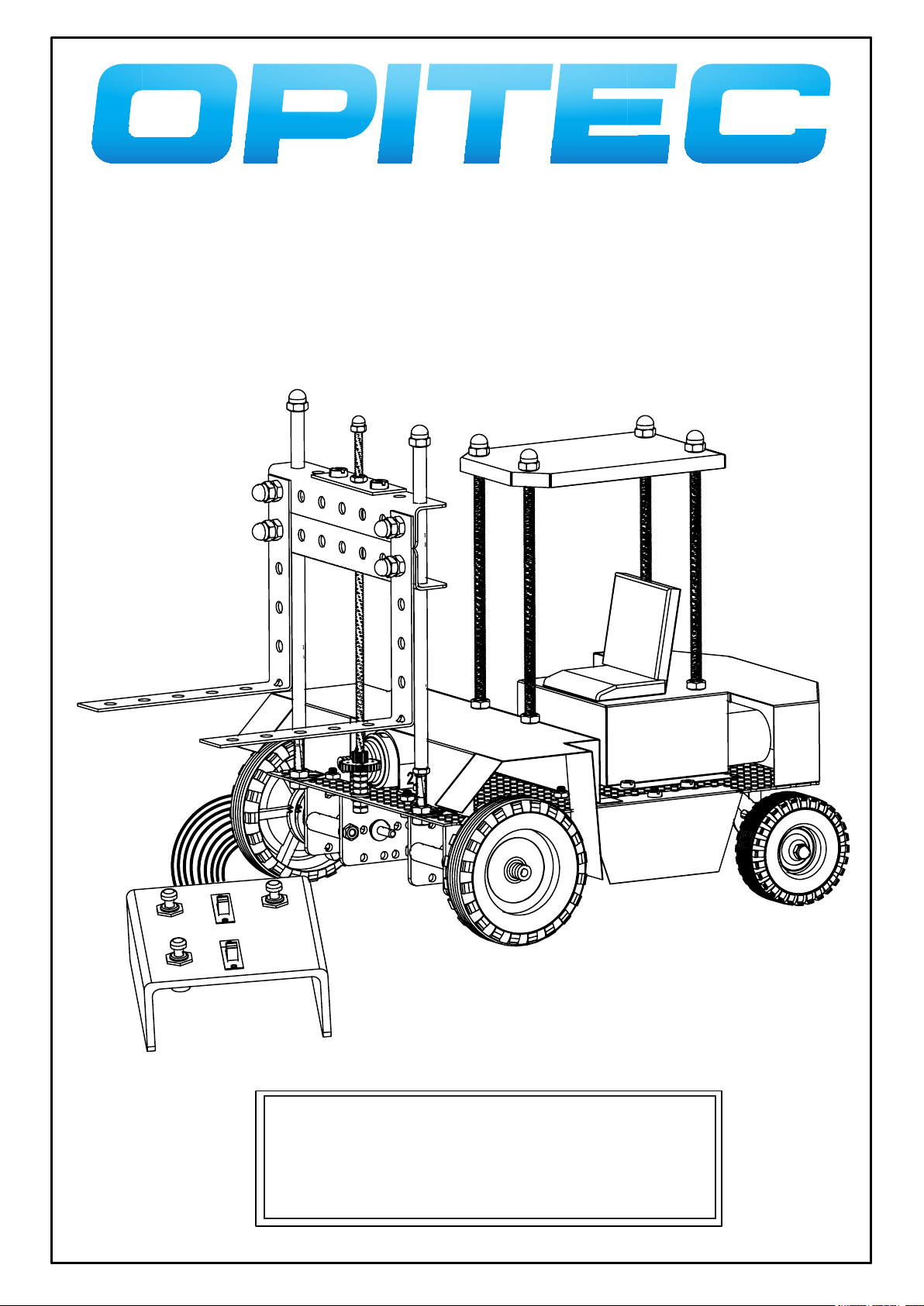
F o r k l i f t t r u c k
“MANITOU”
Please Note
The OPITEC range of projects is not intended as play toys for young
children.They are teaching aids for young people learning the skills of
Craft, Design and Technology.These projects should only be underta-
ken and tested with the guidance of a fully qualified adult.
The finished projects are not suitable to give to children under 3
years old. Some parts can be swallowed. Danger of suffocation!

101.200
1
Parts list
It is recommended that you sort through and identify the various parts before starting this project.
Please remove any ‘burr’ from the metal parts with a file or emery cloth before assembly!
Quantity Description PartNo Material Size
1 Chassis/base 1 Holed metal 130 x 166mm
2 Rear axle bearing 2 Holed metal strip 15 x 60 ( 4 holes)
2 Steering rods 3 Welding rod 1mm x 100mm
2 Wheels (large) 4 Plastic 55mm dia
3 Wheels (small) 5 Plastic 43mm dia
2 Motor R 20 6 Metal 21mm dia
2 Motor drive gear 7 Plastic
2 Angle plates 8 Plastic
4 Distance rollers 9 Plastic 25mm dia
4 Machine screws 10 Steel M3 x 35mm
4 Nuts 11 Steel M3
4 Metal axles 12 Steel 3mm x 70mm
4 Double gears 50/10 13 Plastic Red/brown (tight)
4 Double gears 14 Plastic White grey (loose)
4 Tube spacers 15 Brass
2 Distance washers 16 Plastic red or white
2 Reducers 4/3mm 17 Plastic
2 Fork guides 18 Threaded steel rod M4 x 150mm
1 Hub rod 19 Threaded steel rod M4 x 150mm
2 Fork holder 20 Steel holed strip 5x15 x 105mm (7 holes)
1 Fork coupling 21 Steel holed strip 1x45 (3holes)
2 Forks 22 Steel holed strip 1x15x250mm
1 Fork drive 23 Plastic double gear 30/10 Red/brown
1 Motor R20 24 Metal
1 Motor fixing 25 Steel
1 Drive worm gear 26 Plastic
2 Brass tubes 27 Tube 5mm dia x 250
14 Machine screws 28 Steel M3x 8mm
2 Machine screws 29 Steel M3 x 25mm
6 Washers 30 Steel M3
27 Nuts 31 Steel M3
3 Domed nuts 32 Steel M3
6 Machine screw 33 Steel M4 x 8mm
24 Nuts 34 Steel M4
10 Domed nut 35 Steel M4
1 Steering joiner 36 Connecting block, cut off
2 Battery and seat fixing 37 Sticky pads
1 Seat squab 38 Hard foam or similar
1 Motor cover 39 Cut from sheet metal 200x155mm
2 Side panels 40 0,29 x 200 x200 70 x 45mm
1 Wheel cover 41 Cut from sheet metal 170x132mm
1 Roof 42 0,29x300x150mm 100x70mm
1 Seat 43 70x40mm
4 Roof support 44 Steel/Threaded rod M4 x 100mm
2 Flat connectors 45 Metal 6,3mm
4 Self tappers 46 Steel 2,9x9,mm
1 Hand control housing 47 Polystyrol 3 x80x130mm
1 Press switch 48 Connector
2 Slide switches 49 2 xUM
2 Cable joiner 50 Connecting block (to be cut)
1 Flat cable 51a
1 Round cable 51b
Electrical parts Panels Construction material Lift mechanism Drive system Chassis
Fork lift truck “MANITOU”
101.200
2
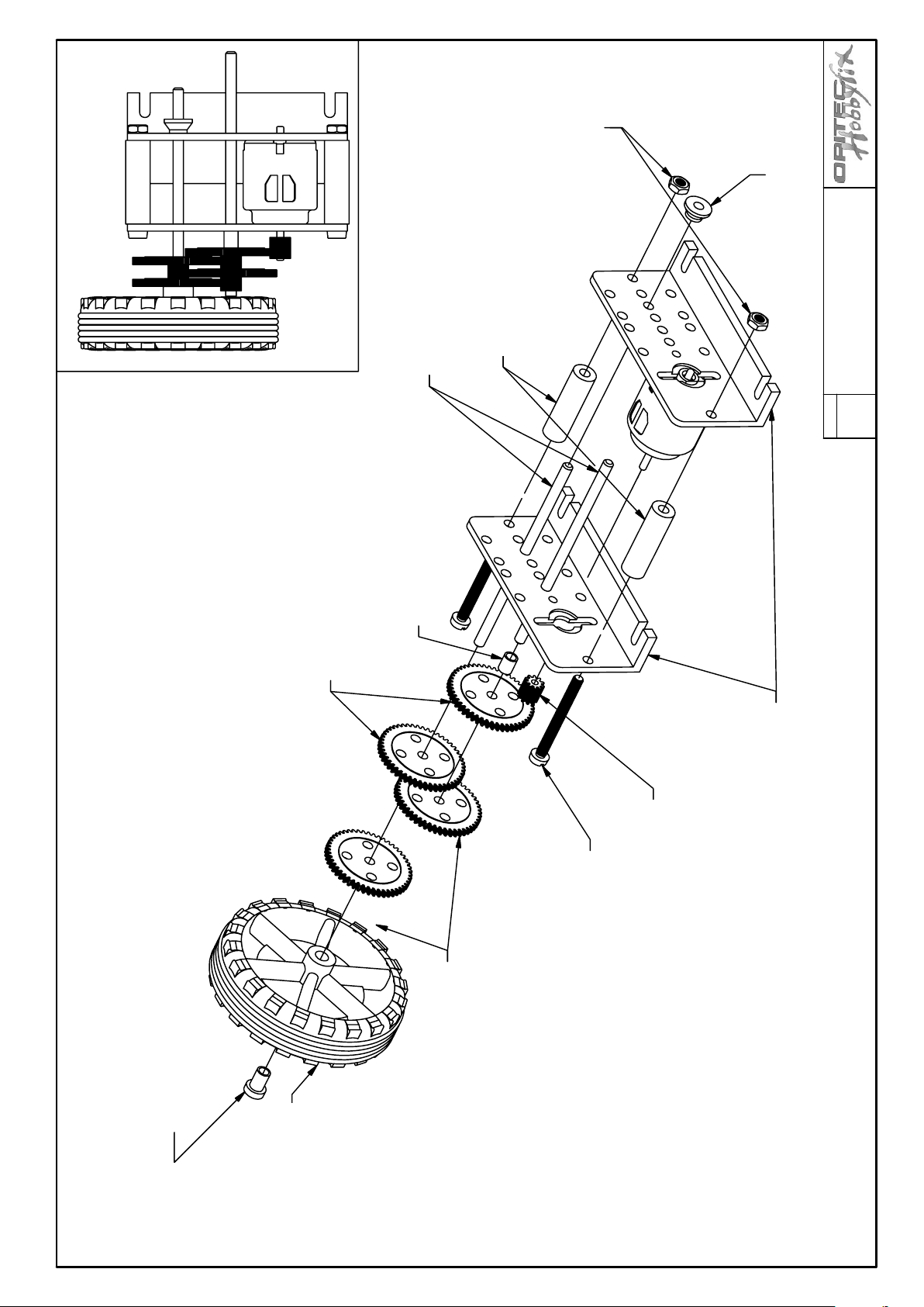
Nuts M3
Plastic washer
Double gears 50/10
White grey
( Loose fit)
Distance pieces
Metal axles ø 3 x 70 mm
Brass tube
Fork lift truck “MANITOU”
Reducer 4/3mm
Drive system
Join to gear part 4
Double gears 50/10
red/brown
(Tight fit)
Motor drive gear
Machine screw M3 x35mm
Parts No. 6-17
Plastic angle plates
The exploded diagram shows the construction of
right hand motor and gearbox.
The left hand motor and gearbox is assembled
the same way in the mirror image.
101.200
3
12
60
3
Q
2
90°
45°
2 x
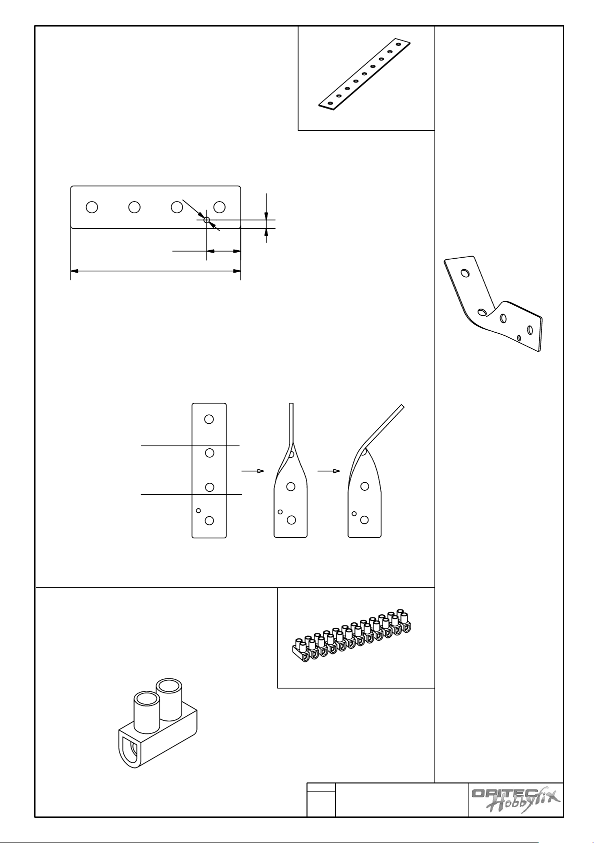
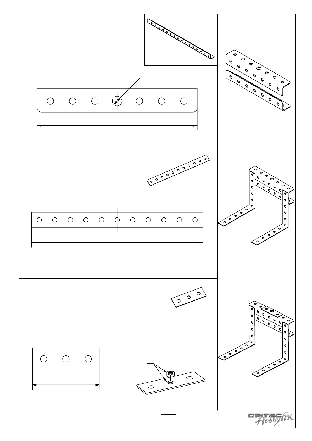
Chassis
Part Nr: 2
Cut two holed metal strips to 60mm long, and
round the sharp corners with a file.
Mark out and drill the 2 diameter in the holed
metal strip
Hold the holed metal strip up to the bottom line in a vice
( See diagram)
And twist the top half ( Upper line) with a pair of pliers,
firstly turn it through 90 degrees and finally bend it
across at 45 degrees
Pliers
Vice
Part No: 36
Cut off one section from the row
of connectors
Fork lift truck “MANITOU”

101.200
4
Part Nr.2
Mount both of the rear axle holders with machine screws M3x8
(Part Nr: 28) in the 11th row 3rd hole in from left and right. Use
two M3 nuts (Part Nr:31)and contra tighten them so that the
holders swivel.
Part Nr. 31
Part Nr..28
Part Nr: 5
To fit the two small wheels as shown
Insert the machine screw M3 x25 (Part Nr: 29) and
washer (Part Nr: 30) from the inside through the
axle holder. Contra tighten with two nuts (Part
Nr:31) and finally fix the wheel with a domed nut
(Part Nr:32 )
Part Nr. 29
Part Nr. 30
Part Nr. 31
Part Nr. 32
Fork lift truck “MANITOU”
101.200
5
90
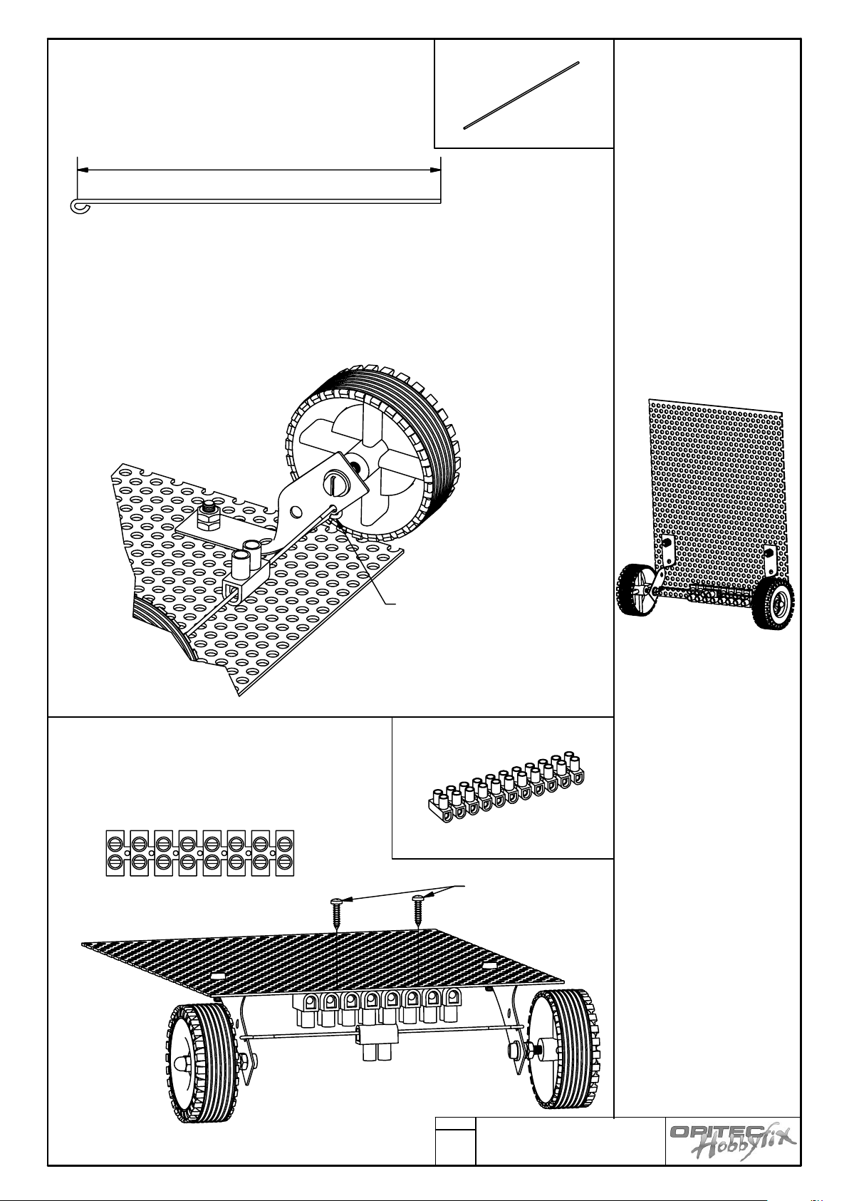
Part Nr:3
Form an eye in one end on the ends of the
welding rod as shown.
Join both welding rods together in a connector block ( lightly tighten)
Hook the eye at the end of rod through the 2mm dia hole in the axle holder.
Tighten the loop afterwards with a pair of pliers so that it cannot spring out.
The tracking can be adjusted later when both sets of wheels are in position.
Part Nr:50
Cut off 8 blocks from the connector block and
fix with 2 self tapping screws (46)
centrally between the two rear axle holders.
Hook the eye in the welding rod
through the hole and tighten
Part Nr. 46
Fork lift truck “MANITOU”

101.200
6
C
1
2
1
2
Part Nr 6
Mount the one motor and gearbox and wheel assembly with 2 machine
screws ( Part No: 28) and nuts ( Part No:31).in the 10th row of holes and 3
holes from the edge 2. Carry out the same
Procedure with the second motor and gearbox
Part Nr. 31
Pos. 28
Part of the left hand drive
Right hand drive
Fork lift truck “MANITOU”

101.200
7
Finished chassis with wheels and gearboxes
Fork lift truck “MANITOU”
101.200
8
105
Q
6
,
5
45
2 x
2 x
165
Fork lift assembly
Part Nr:20
Cut the fork carrier to length and drill the
middle hole out to 6.5 mm diameter
Round the ends with a file
Part Nr:22
Cut the fork assembly to length. Use the
machine screws M4x 8 (Part Nr:23)
M4 nuts and domed nuts (Part Nr: 34 and
35) join them to part 20
(See sheet 9)
Part Nr:21
Cut off a piece 45mm long from a remaining piece
of holed metal strip
Glue (2 part epoxy glue) or solder a M3 nut (Part
Nr: 21) over the middle hole and fit to Part Nr:20
Use the machine screws (Part Nr:33) and nuts
(Part Nr:34)
Glue or solder
in position
Fork lift truck “MANITOU”

101.200
9
Assembling the fork
Nuts M4
(Part Nr: 34)
Domed nut
(Part Nr:35)
Machine screw
M4 x 8
(Part Nr 33)
Nuts M4
(Part Nr: 34)
Front view
Machine screw
M4 x 8
(Part Nr 33)
View from behind
Fork lift truck “MANITOU”

Z
Y
101.200
10
Z
Y
124
Q
5
Part 27
Saw brass tube to length as shown, with a Junior hacksaw
env.
Part Nr: 18
In drive direction
Mount the right hand fork guide (Part Nr: 18) in the first row of
holes in the 3rd or fourth hole in from left. Fix with two nuts M4
(Part Nr: 34) as shown in diagram Z
Mount the other fork guide ( Part Nr:18) at a distance of 90mm
(Seen from centre to centre) and also in the first row of holes (See
diagram)
Part Nr. 18
Part Nr. 18
Fork lift truck “MANITOU”

101.200
11
4
Part: 27
Place M4 nuts ( Part Nr: 4 ) on each fork guide ( Part Nr: 18) and then place
a brass tube (Part Nr: 18) on each guide, finish with M4 nuts
Adjust all the nuts so that the guides protrude 4mm on either side.
Part Nr. 27
Part :19
Mount the fork drive (Part 19) in the middle between the two fork guides.
From underneath place a washer (Part 30) and lock with two M3 nuts
(Part 31)
Part Nr. 19
Washer
(Part Nr. 30)
Part Nr: 23
Finally from above place a washer M3 (Part Nr:30) and 4 M3 nuts (Part 31)
M3 nuts
(Part Nr. 31)
Note: the drive ( Part Nr. 19 ) should be able to turn.
Then then add the drive gear (Part Nr:23) and glue it to the four nuts (Use a two
component epoxy glue or super glue)
Part Nr. 23
Washer
(Part Nr. 30)
Gear 30/10
Glue together
4 x nuts M3
Fork lift truck “MANITOU”

Z
101.200
12
Z
Parts Nr: 24 and 26
Place the worm gear on the motor shaft
Part Nr: 25
Mount the motor and gear so that the worm gear engages lightly with the Fork
drive gear.
Fix the motor in position with the metal loop holder (Part Nr: 25) and two machine screws M3 x 8 (Part Nr: 28) and suitable nuts (Part Nr:31) to the holed metal
sheet.
Fork lift truck “MANITOU”

101.200
13
Part Nr: 20 22
Mount the completed fork assembly. Turn the worm by hand
so that the fork assembly lowers by about a centimetre
Finally add a domed nut to the tops of the guide and drive (
Parts Nr: 35 and 35)
Part Nr. 35
Part Nr. 32
Fork lift truck “MANITOU”

101.200
14
200
2
0
0
300
1
5
0
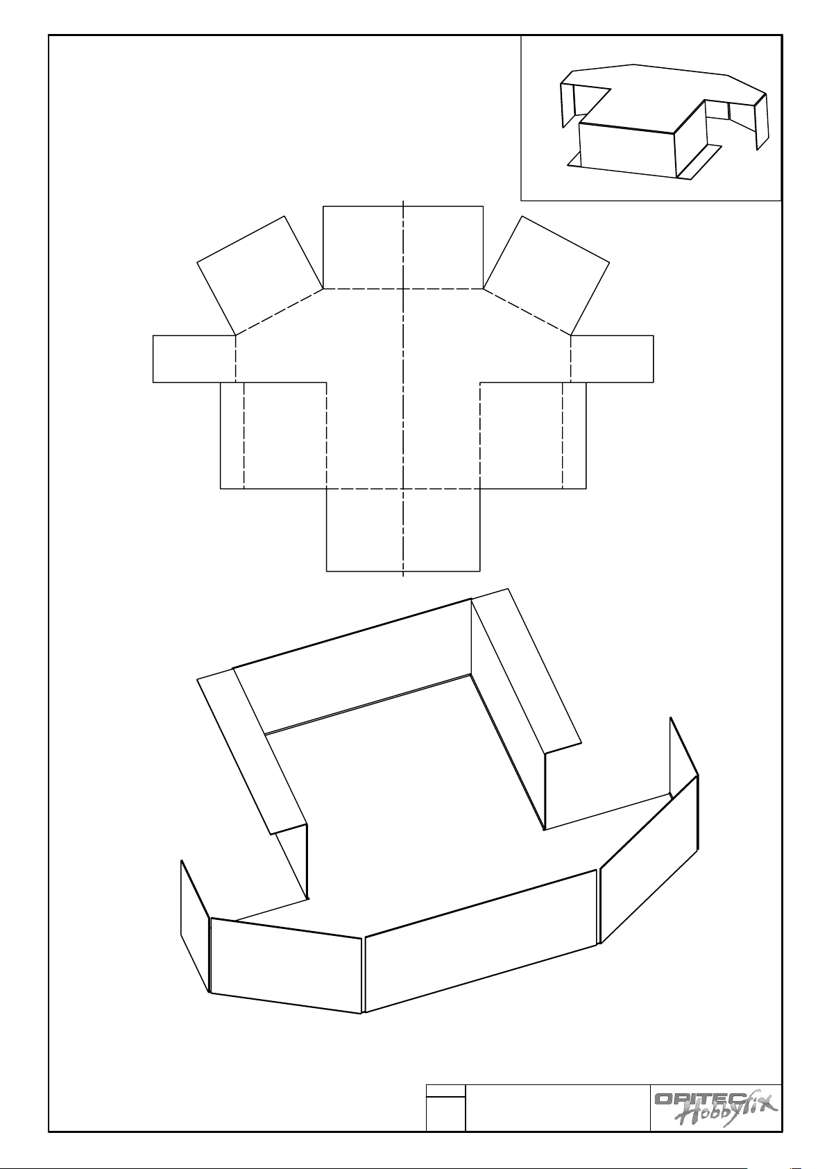
Bodywork
Parts Nr: 39-43
Cut out the patterns 1-6 (See page 23 & 24) and lay them out on the metal sheet, hold them in position with
tape or glue
Cut out the shapes with metal snips along the thicker lines.
In patterns 1 and 4 along with the contour lines other inner cuts must be made. ( Along the thickened lines )
In patterns 2/3 there are also 3mm diameter holes to be drilled. In pattern 6 4mm holes.
Pattern 1
Pattern 2
Pattern 5
Pattern 3
Pattern 6
Pattern 4
Fork lift truck “MANITOU”
101.200
15
1
2
7
3
4
6
5
8
10
9
Part 39
After cutting out pattern 1 (Motor cover) fold the metal sheet
along the broken lines
Use folding bars or a vice for accuracy
View from underneath
Fork lift truck “MANITOU”

101.200
16
80
°
30
35
4
0
4
0
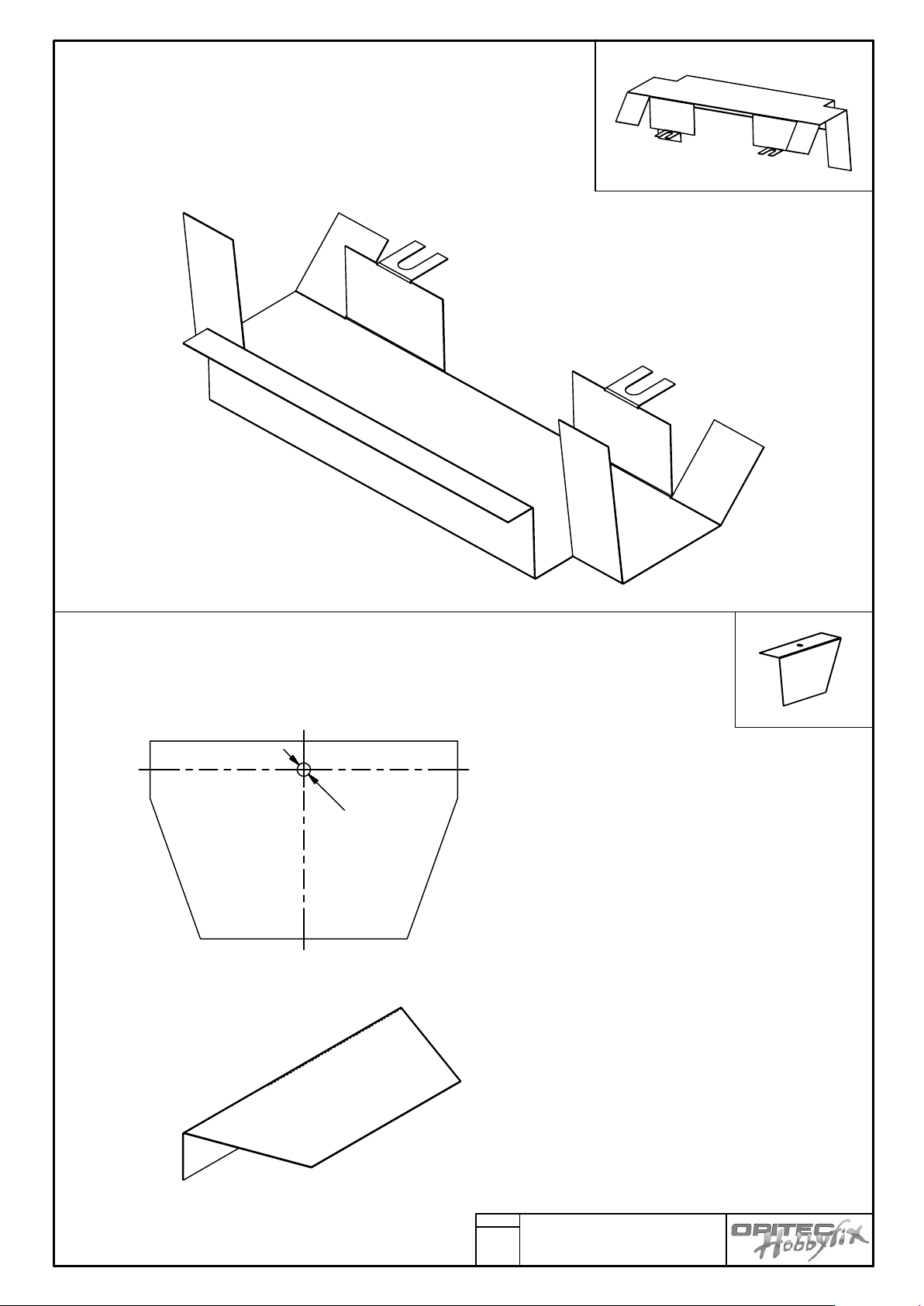
Part Nr:42
Once you have cut out the pattern Nr. 6 drill the 4mm holes
Fold the edges as shown using vice or folding bars.
The small short folds can be folded with pliers
Part Nr:43
View from underneath
Cut out the pattern 5 from the metal sheet. Bend using a vice (Use soft jaws) at an
angle of 80 degrees
Finally add the foam squab and back ( Part Nr :38 ) use contact glue
Shape to suit with a file or sandpaper
Fork lift truck “MANITOU”
101.200
17
Q
3
Part No 41
Cut out pattern 4 . Centre punch and drill the holes. Finally cut out
the slots with a Junior hacksaw. Clean up all edges of the slots
with a needle file
View from underneath
Part Nr:40
Cut out the sides according to patterns No 2 and 3 and drill the 3mm holes
Fold using a vice with soft jaws
Fork lift truck “MANITOU”
101.200
18
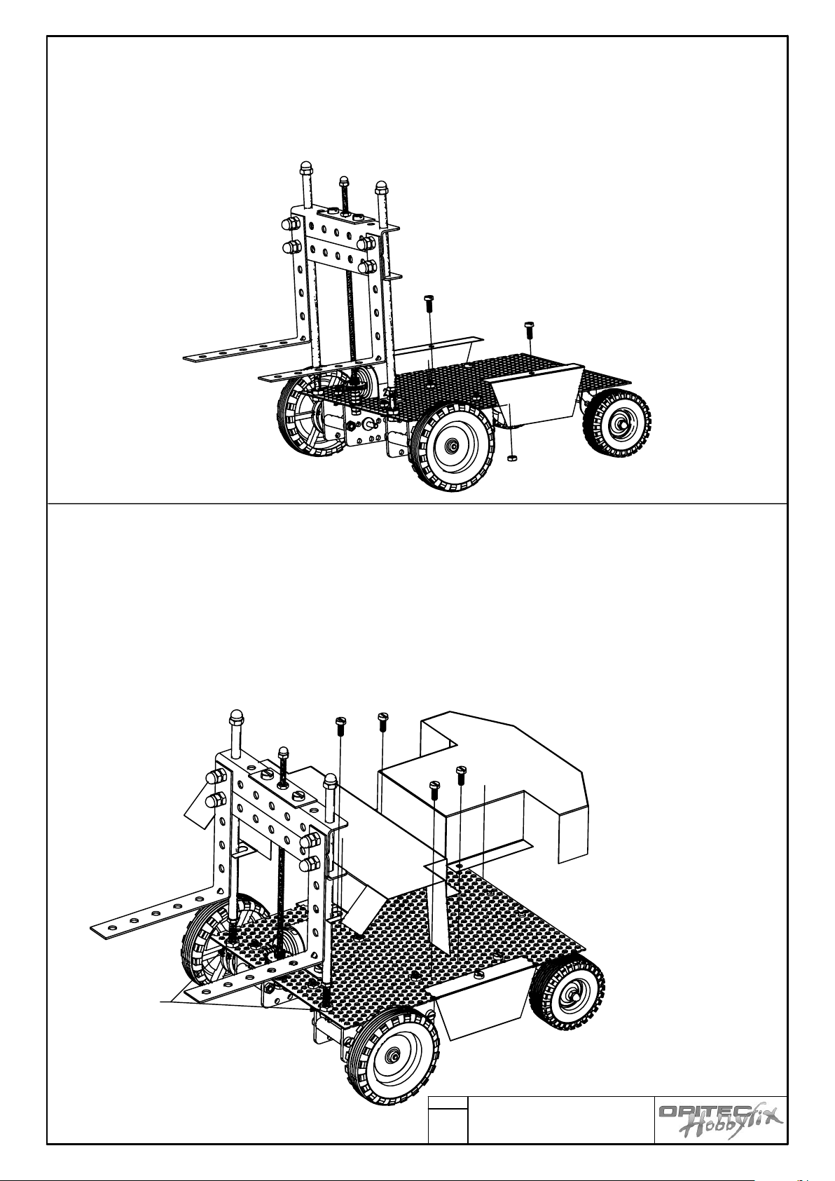
Part : 40
Mount the side panels so that the wheels can turn without rubbing
When you are happy with the position mount the panels with the M3 x 8 ( Part Nr: 28) machine screws and
nuts
Part Nr: 39 and 41
To fit the bodywork you will need to loosen the nuts on the fork guides where they join the chassis ( Holed
metal sheet )
Now mount the bodywork ( Slide one part under the loosened nuts ) and adjust to fit. Mark the holes for parts
39 and 41 from underneath with a felt tip pen. Centre punch the positions and drill them with a 3mm hole.
Now fit the bodywork with 4 machine screws ( Part Nr:28 ). Do not add nuts underneath
Fork lift truck “MANITOU”
101.200
19
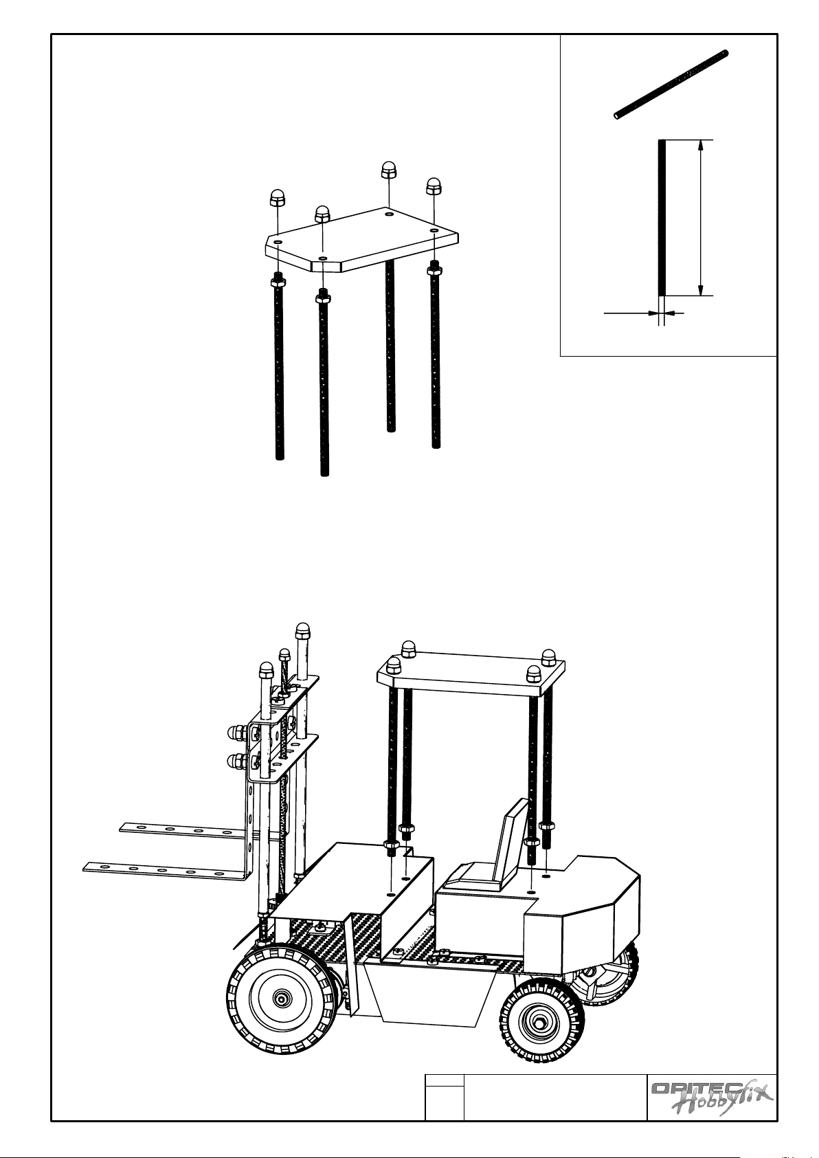
1
0
0
4M
Part Nr: 44
Mount the finished roof ( Part Nr 42 ) with hex.nuts and dome nuts on
the 4 pillars ( Part Nr:44)
Now hold the roof and pillars in position on the bodywork and mark the four holes.
Centre punch an drill the four 4 mm holes
Add another set of M4 (Part Nr:34 ) nuts to the bottoms of the pillars then mount the cabin on the holed
chassis with M4 nuts
Fork lift truck “MANITOU”
101.200
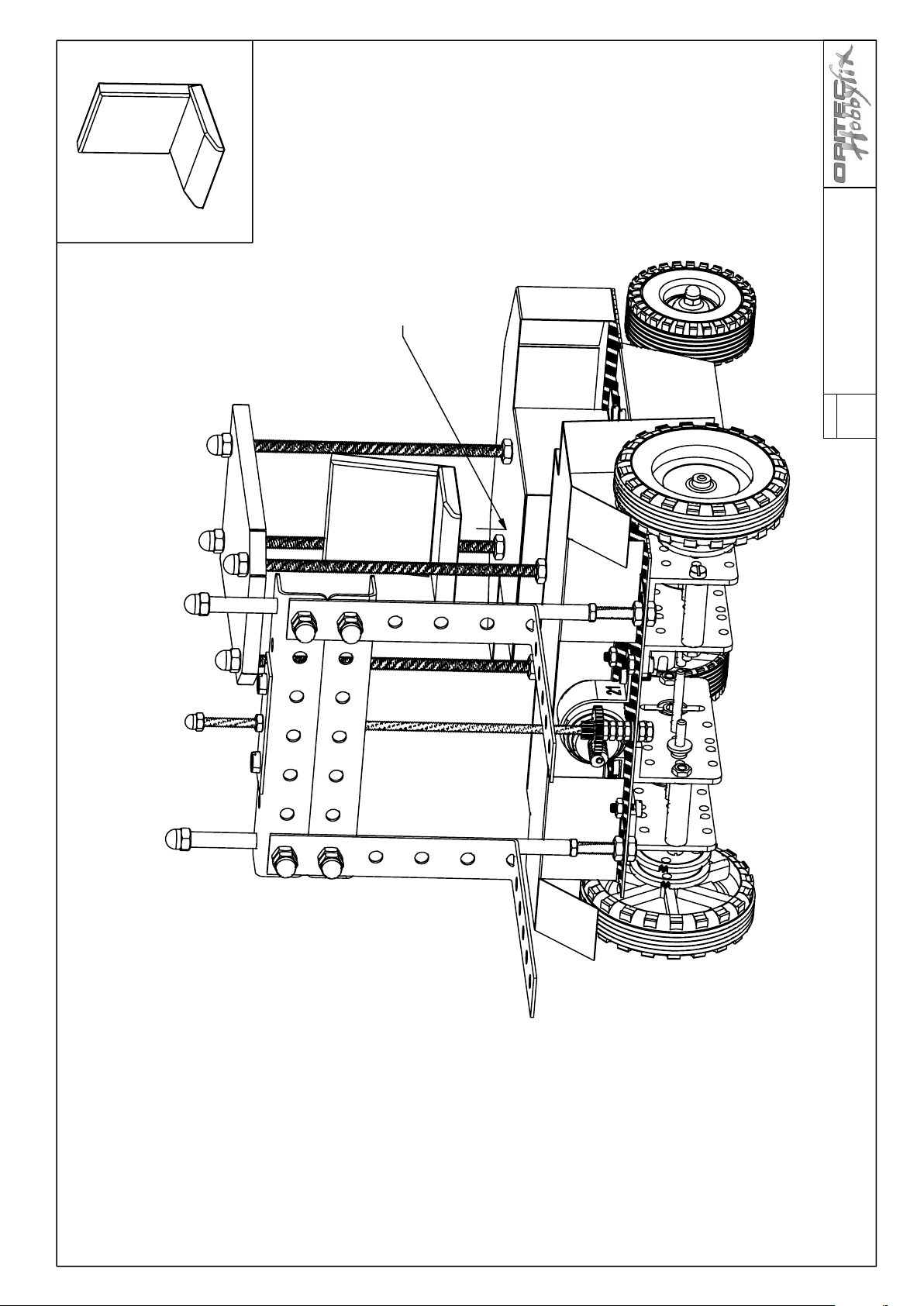
20
Use double sided tape
Fork lift truck “MANITOU”
Part Nr:37
Finally fix the seat using double sided tape
(Part Nr: 37) Use the second pad to fix the battery
101.200
21
4,5 V
1
2
3
4
5
6
7
8
1
23
456
7
8
3
0
7
0
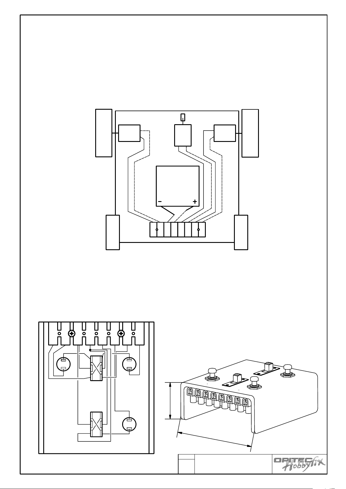
Electrics
Part No: 45-51b
1. Mount the battery under the bodywork using the remaining double sided sticky pad
2 Insert a piece of cable in the joiner block 3 and 4. Solder or crimp a connector on the ends and join to the
battery
3 Wire up the components according to the diagram
Broken line represents the red wire = Plus pole
Continuous line represents the black wire + Minus pole
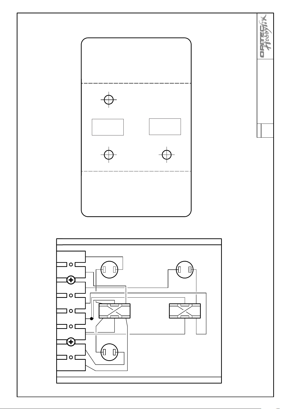
4. Hand steering set
Mark out and drill the holes in the polstyrol sheet ( Part Nr:47 ) for the switches 7,5mmdia and file out the
long shaped hole (Pattern A , page 22 ).
Finally bend the U shaped form. Use a hot air gun or strip heater ( Attention !! N.B. be careful of burns )
Glue the switches with super glue ( Be careful not to get glue in the switch )
Fit the connector block with two self tapping screws ( Part 46) see plan ( See page 22 )
5. Connect the hand control, with the flat band cable to the
model. Connect the numbers from the hand control to the
corresponding numbers on the chassis connector.
View from underneath
View from underneath
Fork lift truck “MANITOU”
101.200
22
1
2
3
4
5
6
7
8
drill ø 7,5 mm
Pattern A
Fork lift truck “MANITOU”
The broken lines denotes folds
The thick lines represent the outer shape of the pattern
Vergrößerung des Verdrahtungsplans

24
D101200#1
101.200
23
Q
3
Q
3
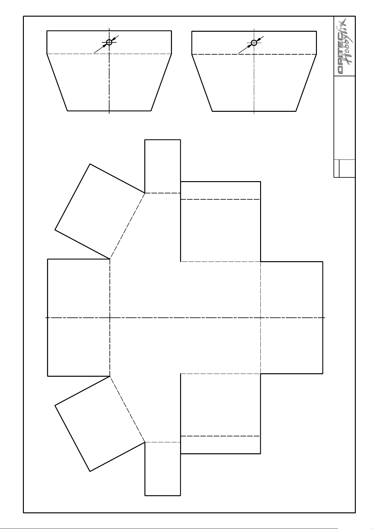
Pattern 2
Pattern 3
Fork lift truck “MANITOU”
Pattern 1
The broken lines denotes folds
The thick lines represent the outer shape of the pattern


101.200
24
Q
4
R
3
Pattern 6
Pattern 4
Fork lift truck “MANITOU”
The broken lines denote folds
The thicker lines represent the outer shape of the pattern
Pattern 5

 Loading...