

OPISYS USHR-0819H, USHR-0819L Installation Manual
Users Guide
&
Installation Manual
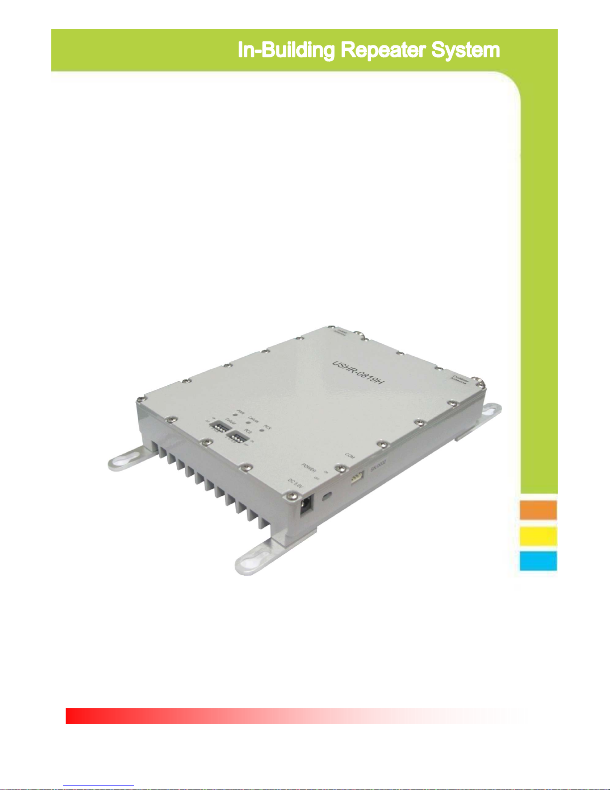
USHR-0819H
Page 2
- Content -
1. General Information
2. System Components
3. Installation
4. Trouble Shooting
5. Specification
6. Certificates
7. Memo
This device complies with Part 15 of the FCC Rules. Operation is subject to the following
conditions; This device complies with the Industry Canada license-exempt RSS standard(s).
Operation is subject to the following conditions;
(1) This device may not cause harmful interference.
(2) This device must accept any interference received, including interference that may
cause undesired operation.
CAUTION: Changes or modifications not expressly approved by the party responsible for
compliance could void the user’s authority to operate this device.
Statement : The term “IC” before the radio certification number only signifies that Industry
Canada technical specifications were met.
CAUTION : The User that modifications to the unit may void the user’s authority to operate
this device.
To maintain compliance with RF energy exposure guidelines, the antenna used for this
transmitter must be maintained a separation distance of at least 20cm from the user body
when transmitting.
Co-located or operated in conjunction with any other antenna or transmitter is prohibited.
Page 3
1. General Information
1.1. Precautions
1.1.1 Do not drop the device
- It may damage the product and its function
1.1.2 Do not place near magnetic material
- It may cause of possible malfunction
1.1.3 Product is recommended to be used with original AC/DC adapter
1.1.4 Install the product where it is recommended
- It may not properly operate if it is not recommended location
1.1.5 Do not disassemble/ repair the product
- Warranty may void once you disassemble the product.
1.1.6 Turn off the device immediately if a smog or any strange odor is
detected from the product.
1.1.7 Use contained bolt to install on the wall. Make sure it is safely
installed before operation
Reference : Direction/Information for the proper operation
Cautions : Information for users to avoid malfunctions
Warning : Instruction for users to avoid unexpected hazard
1.2 . Features
1.2.1. Summary
This device may be installed on residential area, office, warehouse etc. .
Following is advantage of using in-building repeater system.
This is RF type amplifier for Cellular800MHz and PCS1900MHz signal
enhancement. It covers GSM, EDGE, CDMA, WCDMA mobile phone users.
(Please refer repeater specification for operating Frequency Range info.)
1.2.2 . Features
Page 4
I. Decrease dropped call rate
II. Increase signal strength
III. Improve Data / Voice quality
IV. Prolong hand phone battery life
V. Improve data Communication Rate
I. Wider Coverage area
- Gain 75dB .
II. ALC(Automatic output Level Control)
- Stabilize operation in any radio environment
III. Fulfill IS-95A spurious specification at +20dBm output power
- Provide high Data Communication Rate
IV. Easy gain control by dip switch located on the front side of product
V. Support dual band
- enable to connect service from multiple carrier simultaneously
- 800MHz / 1900MHz service simultaneously
- 800MHz / 1900MHz adopt independent operation algorithm
VI. Check status of product by LED indicator
VII. Manage and control product by GUI(Graphic User Interface)
- Please ask professional installer about GUI Program
VIII. Enable to stay connected in homes and offices
- Please ask professional installer for installation on homes & offices
IX. GSM, EDGE, CDMA, WCDMA ready
Page 5
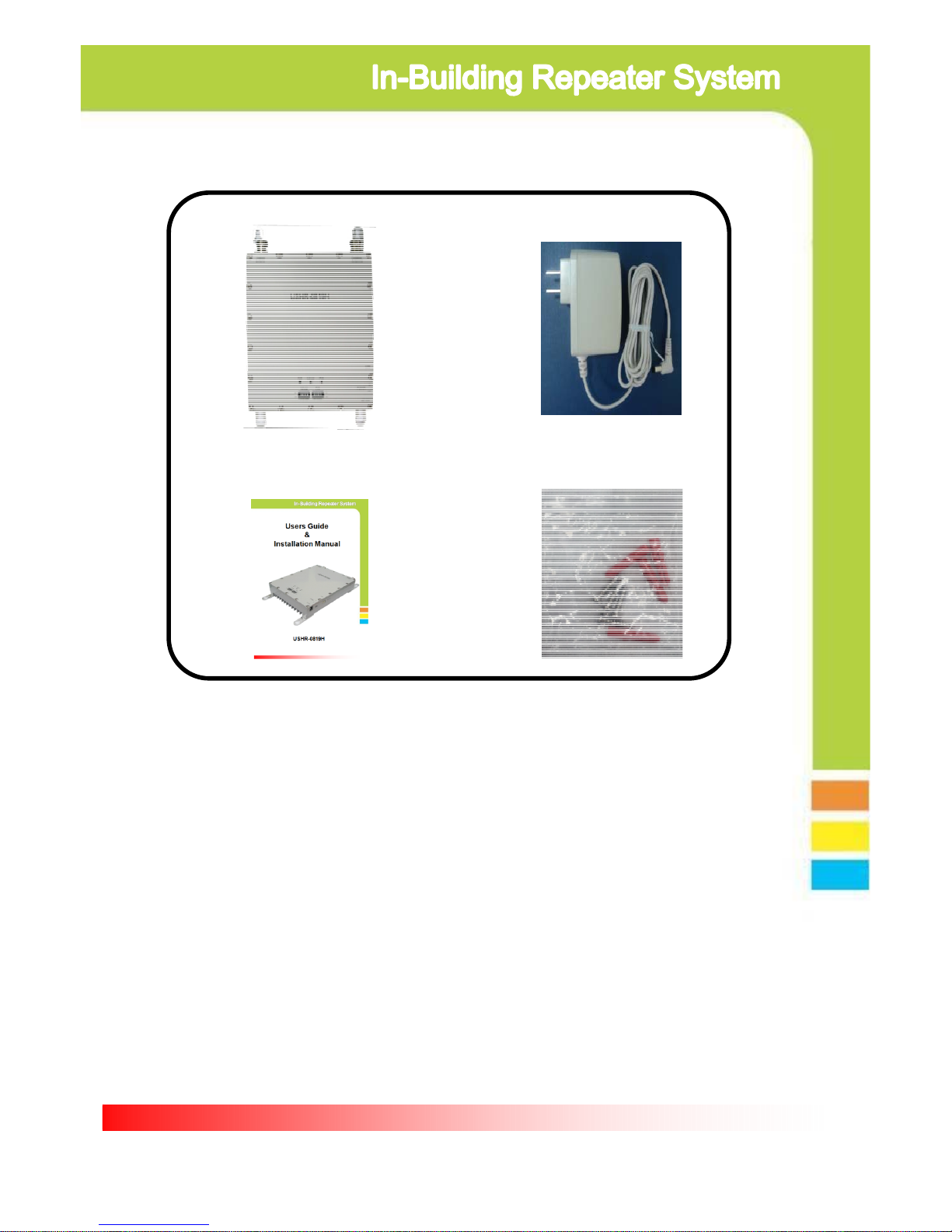
① Dual Band Repeater
② AC/DC Adapter
③ User Manual
2. System components
④ Installation bolts
① Dual band Repeater : BTS and mobile phone signal booster
② AC/DC Adaptor : 110v power supply
③ User Manual : Operation manual
④ Installation Bolts : Holds repeater on the vertical wall
Page 6
3. Installation
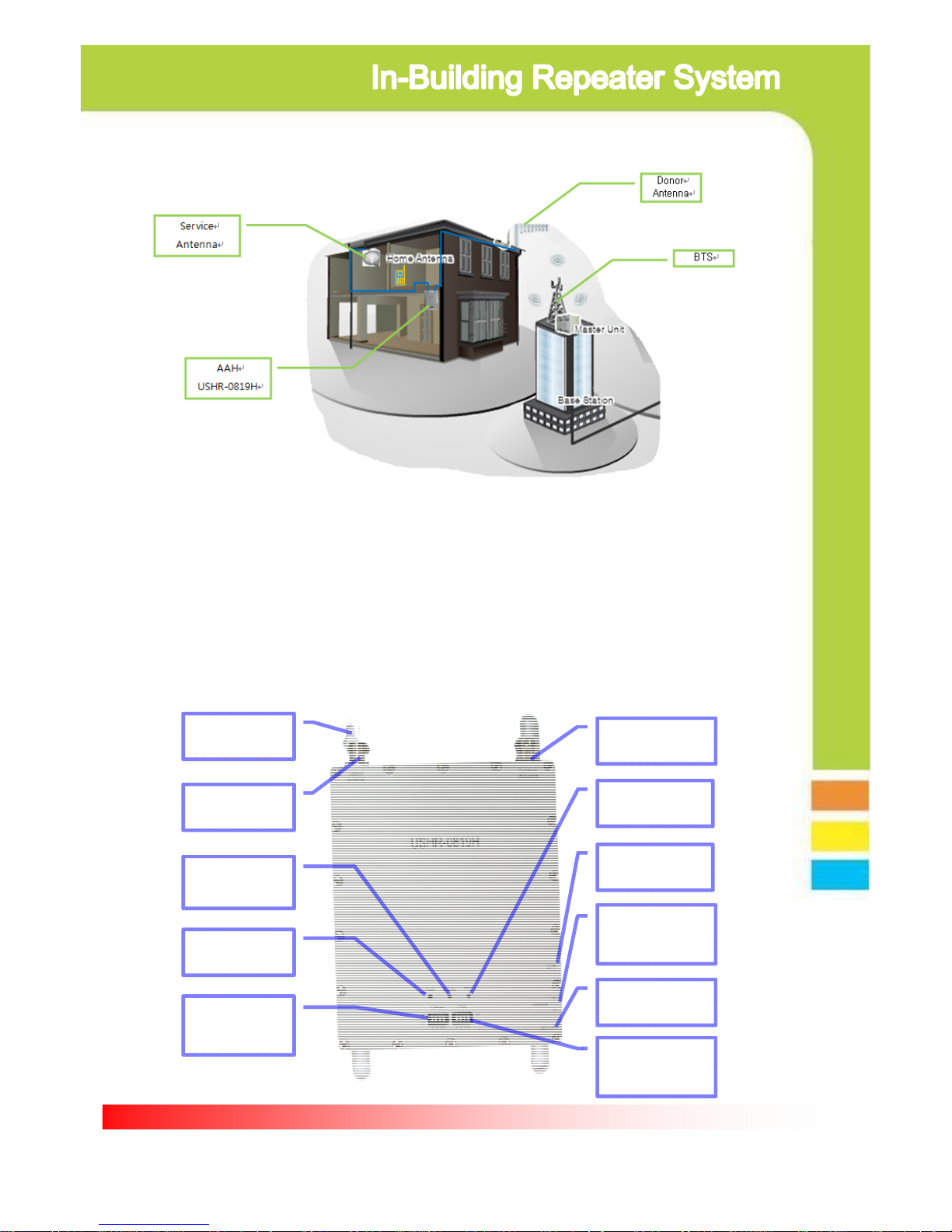
3.1. Installation diagram
3.2. Repeater
Service ANT
Port
Donor ANT
Port
Cellular
Status LED
POWER
LED
Cellular
Gain control
Dip Switch
PCS
Gain control
Dip Switch
POWER Jack
Port
Power
ON/OFF
Switch
PCS
Status LED
GUI
PORT
Installation
Bracket
3.1.1. Install Donor Antenna on higher location to avoid any signal
interference.
3.1.2. Install service antenna at appropriate location such as wall or
roof ceiling. Make sure service antenna is not blocked by
furniture or hope appliance.
3.1.3. Use enclosed bolt to fix repeater on the wall and plug in power
adaptor.

Page 7
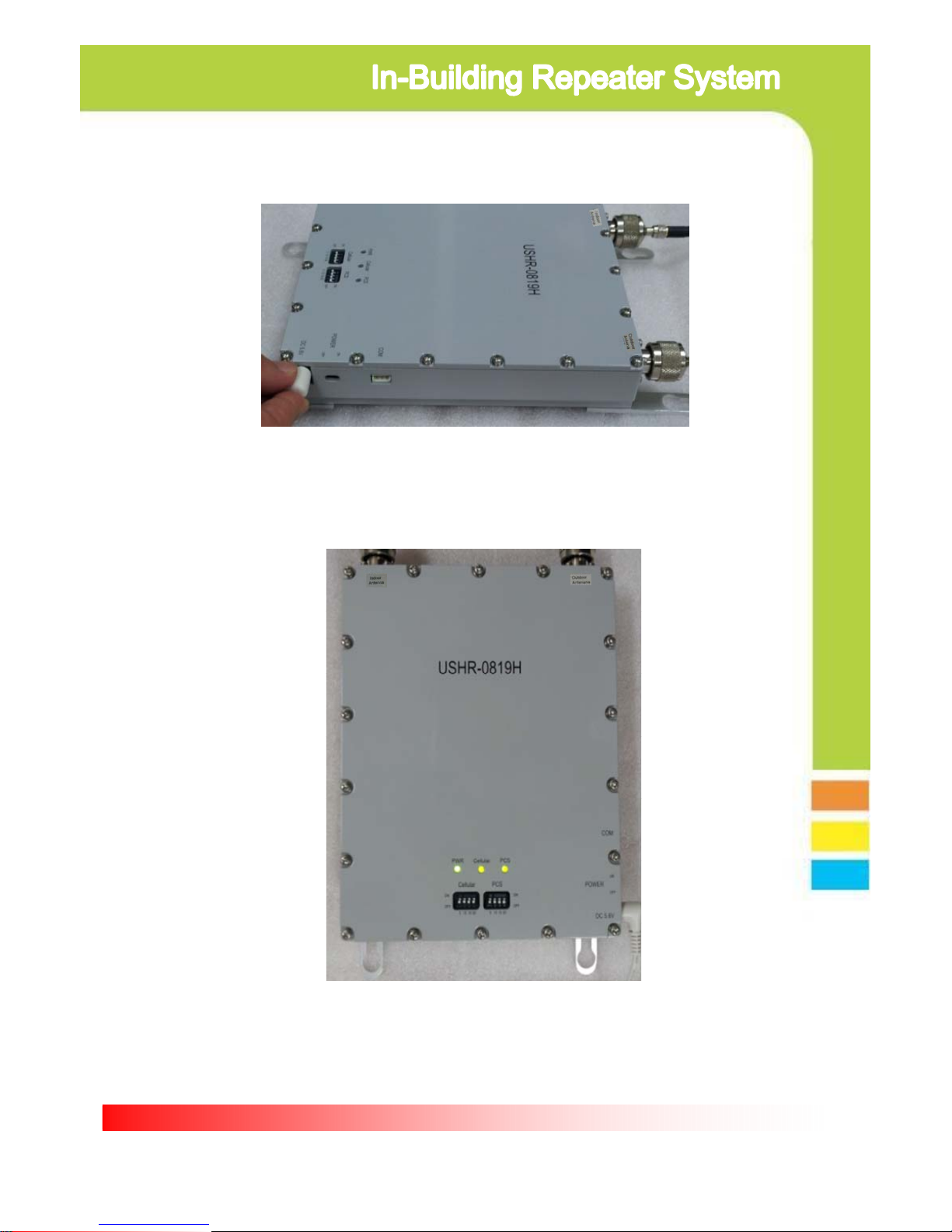
3.3. Repeater and Antenna connection
3.3.1. Connect donor antenna to RVS connector as shown below.
3.3.2. Connect Service antenna to FWD connector as shown below.
3.3.3. Plug in power adaptor to power outlet.
Page 8
3.3.4. Plug in AD/CD adaptor to connector listed as DC5.6V
3.3.5. Once power is on, it will show 3 green LED light on the front of
product as shown below.
Page 9
4.1.1. Power on status
4.1.2. Power off status
4.1.3. Cellular normal operation condition
4.1.4. During normal Cellular operation, it detects excessive input signal or
it is under oscillation condition due to insufficient isolation between
antennas
4.1.5. Due to excessive input signal or oscillation, it cut off circuit to protect
hardware
4.1.6. PCS normal operation condition
4.1.7. During normal PCS operation, it detects excessive input signal or
it is under oscillation condition due to insufficient isolation between
antennas
4.1.8. Due to excessive input signal or oscillation, it cut off circuit to protect
hardware
4. Trouble Shooting
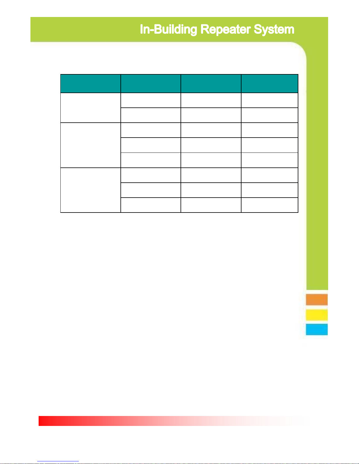
4.1. LED Status
Item GREEN LED RED LED
Problem
Reference
PWR
ON - See 4.1.1
OFF OFF See 4.1.2
Cellular
ON - See 4.1.3
- ON See 4.1.4
OFF OFF See 4.1.5
PCS
ON - See 4.1.6
- ON See 4.1.7
OFF OFF See 4.1.8
 Loading...