

Page 1
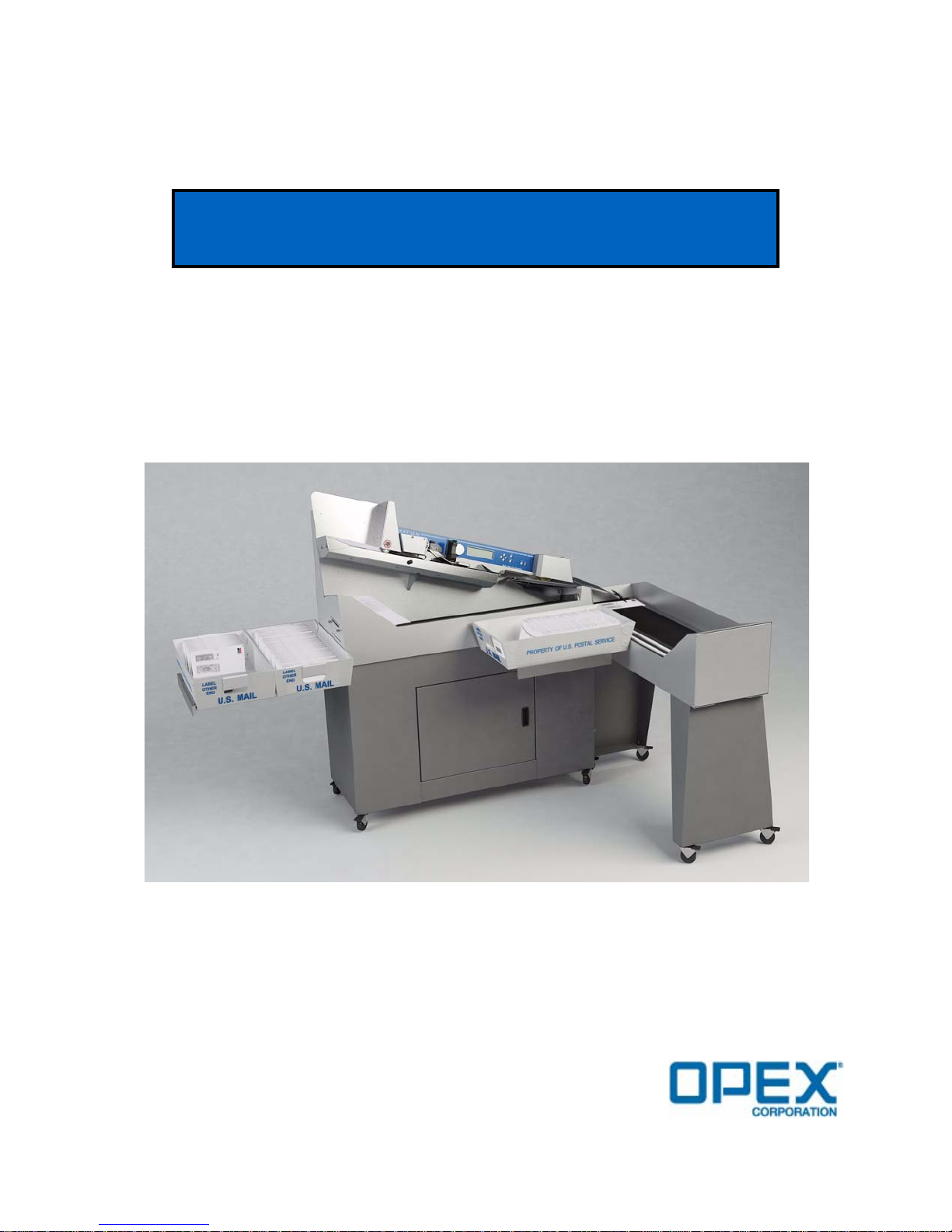
MODEL 306
USER MANUAL
AUGUST 2011
Page 2

®
Copyright © 2011 OPEX
Corporation
All rights reserved. Printed in the United States of America.
No portion of this manual may be reproduced in any form or by any means, or stored in a database
or retrieval system, without the express, written permission of OPEX
To request permission, contact:
®
OPEX
Corporation
ATTN: Legal Department
305 Commerce Dr.
Moorestown, NJ 08057-4234
®
Corporation.
Page 3

Table of Contents
Introduction................................................................................................ 2
Safety......................................................................................................... 3
Overview of Model 306 Operation ............................................................. 5
Functional Description............................................................................... 6
Machine controls........................................................................................ 7
Operating Instructions................................................................................ 9
Supervisor Operations............................................................................. 19
Job Parameters ....................................................................................... 31
Statistics .................................................................................................. 44
Troubleshooting....................................................................................... 48
Routine Maintenance............................................................................... 50
Table of Contents
Specifications........................................................................................... 53
1Model 306 User Manual - OPEX Corporation
Page 4

Introduction
Introduction
Omation Model 306 & Model 306s
High volume, high speed envelope opener with optional sorting capabilities
For more than thirty years, Omation products have been a staple in mailrooms
across the globe. The all-new Model 306 contains significant technological improvements over its predecessor, the Model 206 Envelopener, which has been the world’s
best selling envelope opening device for more than a decade.
The Omation Model 306, with its ability to operate at a rated speed of up to 40,000
envelopes per hour, contains OPEX’s latest mail opening technology and sets a new
standard for high volume mail processing. The improved milling cutter with 8 cutdepth positions removes chips as small as 0.01” from the envelope edge, producing a
soft, feathered edge while protecting valuable envelope contents. Even UPS and
FedEx delivery envelopes are no match for the Model 306. Equipped with a new and
robust operator control software interface, job setup can be done with ease and flexibility.
Most significantly, the Model 306 is also available with enhanced sorting capabilities
as the Model 306s. Envelopes can be sorted to two locations based on programmable
criteria such as thickness, length, and height. Optional batching capability allows
items to be grouped together in pre-selected lot sizes.
Sorting options make the Model 306s a perfect fit for applications that require verification of contents either before or after extraction: like claims processing,
remittance, and vote-by-mail. Because of its ability to differentiate between “clean
mail” from “exception mail.” The Model 306s also helps to ensure maximum productivity from mail extraction equipment by allowing operators to concentrate on
extracting envelope contents from “clean” batches instead of trying to handle
exceptions at the same time.
2 Model 306 User Manual - OPEX Corporation
Page 5

Safety
Safety conventions used in this manual
Safety
The information provided in this section is intended to educate the user on various
safety issues regarding the Model 306.
Specific safety information is listed throughout this manual in the form of
“DANGER,” “WARNING,” and “CAUTION” statements. Pay close attention to these
statements, as they contain important information on avoiding potential hazards to
yourself or to the equipment. An explanation of these statements is provided below.
• Danger statements - are used to indicate immediate hazards that WILL result in
severe personal injury or death.
• Warning statements - are used to indicate hazards or unsafe practices that
COULD result in severe personal injury or death.
• Caution statements - are used to indicate hazards or unsafe practices that
COULD result in minor personal injury or damage to equipment or property.
The following safety labels appear on the machine, and must be observed.
FIGURE 1: Electrical warning label
This label is to warn the techician to turn off the AC power switch and disconnect the
power cord before opening and servicing the Model 306. Servicing of the machine is
to be performed by Authorized OPEX Technicians only. There are no user-serviceable
parts within the machine.
FIGURE 2: Feeder warning label
This label is to warn the user to keep loose objects away from any exposed, moving
parts of the machine. The moving parts of the Model 306 can become jammed and/or
damaged by foreign objects. Keep hands, hair, loose clothing and jewelry away from
the moving parts.
3Model 306 User Manual - OPEX Corporation
Page 6

Equipment safety precautions
!
!
Equipment safety precautions
WARNING:
• Do not attempt to clean the machine while it is running. A cloth (or similar
material) should never be used to clean moving parts such as belts or rollers. The
use of such material on moving mechanisms can result in damage to the machine
or severe personal injury. If a belt, roller, gate or similar part needs to be cleaned,
hand-crank the part during cleaning or clean it while stationary.
• Do not use flammable, high pressure, “canned air” to clean paper scraps and dust
from the machine.
• Do not place fingers in the feed area while running the machine.
• Do not place fingers in the cutter area. The cutter blades are sharp and may cause
cuts, should you inadvertently come in contact with them whether the machine is
running or not.
• Do not set liquids on the Model 306 which could spill into the machine.
WARNING!
Ergonomics
Follow these additional safety precautions whenever installing, operating,
servicing, or maintaining the equipment described in this manual.
Unplug the machine from the power source to remove power from the machine
for servicing or when moving the machine.
As in any occupation which requires you to perform the same motion repeatedly
during the course of your work, it is important to consider how you perform your
task. Always use proper operating procedures when working at your Model 306.
Using improper procedures can result in a potentially serious injury.
To reduce possible risks, we strongly urge you to follow these suggestions:
• If you need to use a chair, maintain an upright body posture. Avoid the tendency
to slump in your chair. The angle between your torso and thighs should always be
90 degrees.
• Occasionally change the angle of your posture for greater comfort.
• If possible, avoid operating the machine for longer than a single 8-hour shift.
While no suggestions can guarantee completely against work-related injuries, you
will certainly increase your comfort and safety while operating the Model 306 if you
put these suggestions into practice. The Model 306 has been designed with you in
mind. If it is operated correctly, you should find your work experience comfortable
and enjoyable.
4 Model 306 User Manual - OPEX Corporation
Page 7

Overview of Model 306 Operation
These steps provide a quick overview of the Model 306 Operation. For details on
operating the Model 306, refer to “Operating Instructions” on page-9.
1 The operator loads mail onto the feed hopper. Normally, the operator can load a
comfortable handful of mail directly from the Post office mail trays.
2 The operator starts the Model 306 by pressing the Start button.
3 The operator uses the keypad to login and select the correct operator.
The operator may also have to enter a password.
4 The operator uses the keypad to select a job.
5 After selecting a job, the screen may prompt the operator to verify or adjust
settings such as: cutter, printer, height detect and/or thickness detect positions.
6 The operator uses the keypad to select RUN, and presses the Enter button to begin
operation.
7 Envelopes are fed from the feeder towards the retard stones.
8 The retard stones singulate the envelopes and sends them past the height and
thickness measurement areas. The envelopes are measured by the sensors in this
area (length, thickness, and/or height) and the envelope count is incremented.
9 The envelope moves through the milling cutter where the top side of envelope is
cut (if the cutter is set to any position other than Position 0=no cut).
Overview of Model 306 Operation
10 Envelope moves towards the sort gate.
11 If sorting is enabled, the sort gate directs the workflow to the correct path.
5Model 306 User Manual - OPEX Corporation
Page 8
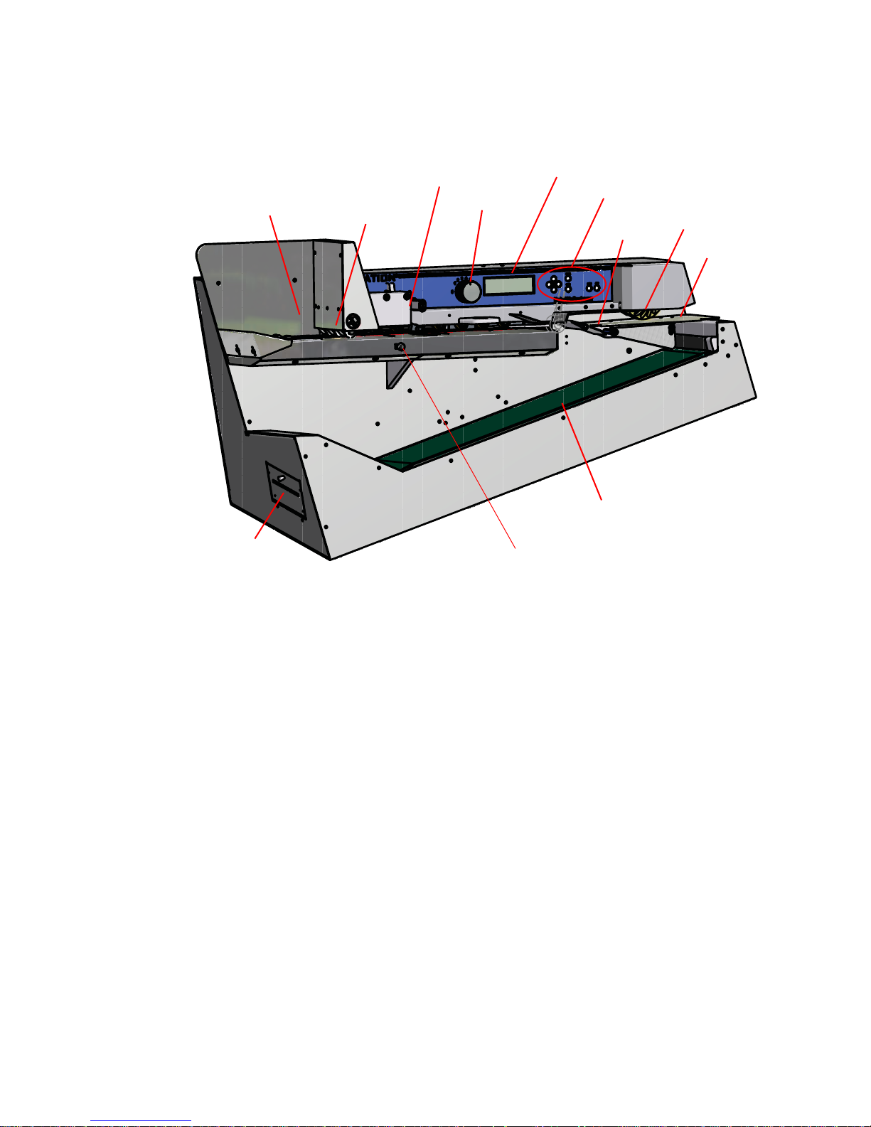
Functional Description
Height measurement
Lower conveyor
Report printer
Feeder
Retard stones
Thickness measurement
Cut depth knob
Divert path
Sort gate
Information display
Feed assist wheel
Button keypad controls
Functional Description
Feeder - Envelopes are loaded onto the feeder at the top left of the machine. This
area is also often referred to as the hopper.
Retard stones - used to singulate and feed the stack of envelopes into the machine
for subsequent processing.
Cut depth knob - used to set the depth of the cut - from 0.01” (0.03 cm) from the
envelope edge (Position 1), up to 0.125” (0.32 cm) in depth (position 8). Cut Position 0
(no cut), can be used to sort envelopes without cutting them.
Information display - backlit LCD screen provides the user interface.
Button keypad controls - used for navigating the menus and starting/stopping the
machine.
The sort gate, thickness measurement and height measurement areas of the
machine are shown.
When sorting, the gate is used to divide the workflow into two paper paths. Path #1 is
sent to the lower conveyor and path #2 is diverted towards a feed assist wheel
where it is sent to an additional conveyor (not shown).
Report printer - located on the left side of the machine, provides a hard copy of job
and operator statistical information.
6 Model 306 User Manual - OPEX Corporation
Page 9
Machine controls
Enter
Cancel
Start Stop
Up Arrow
Down Arrow
Left Arrow
Right Arrow
SELECT JOB
AMEX001
AMEX004
CITI003
PNC001
TD002
WACH003
AMEX003
CITI002
GMAC002
TD001
WACH002
WACH005
AMEX002
CITI001
GMAC001
PNC002
WACH001
WACH004
Scrollbar denotes
position in list
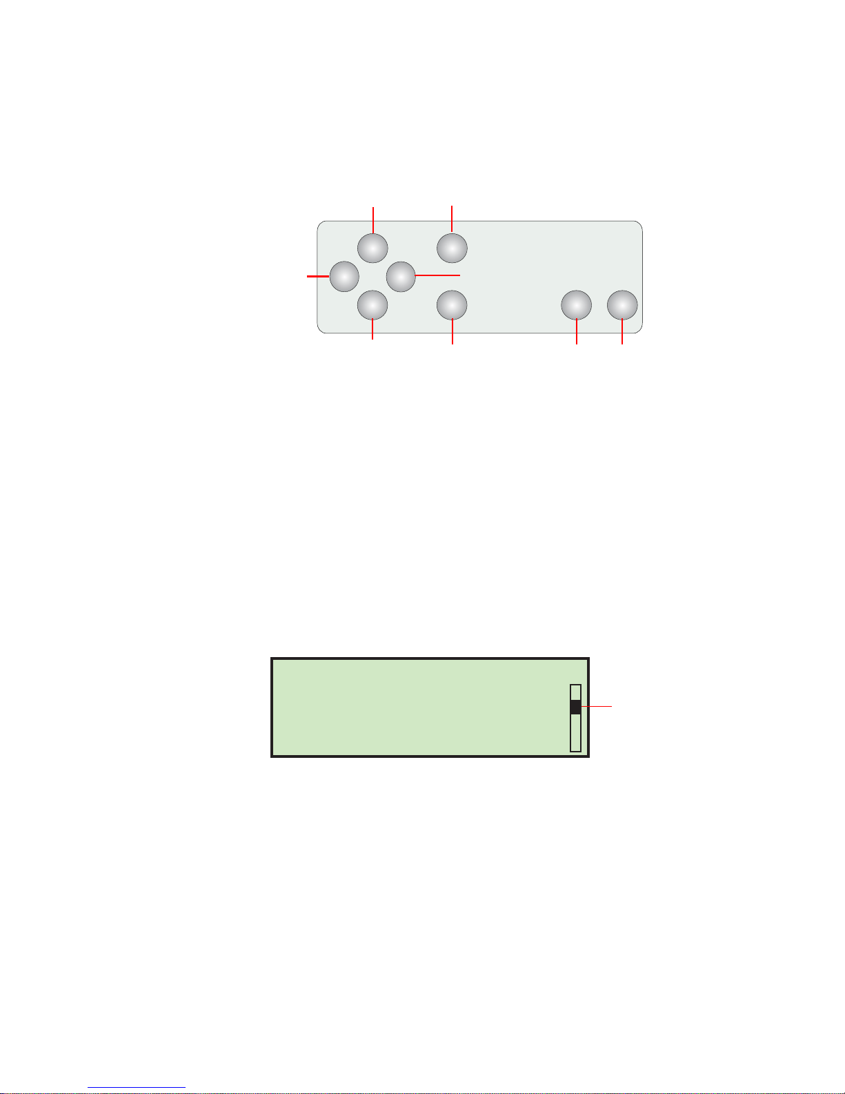
The Model 306 controls are located on the keypad to the right of the operator as
indicated in Figure 3.
FIGURE 3: Model 72 keypad button names
Start button - used to turn on the Model 306.
Stop button - used to turn off the Model 306.
Machine controls
Enter button - used to make selections that are shown on the LCD display.
Cancel button - used to cancel actions (such as to stop a job run), or back out of a
screen.
Arrow buttons - used to navigate through the data on the LCD screen.
Enhanced Scrolling
When a list or table has more information than can be displayed on the screen, a
scroll bar will be displayed on the right side of the screen. The scroll bar gives you a
relative idea were the cursor is in relation to the top and bottom of the list.
FIGURE 4: Typical enhanced scrolling screen
Keypad button functionality
Up Arrow Press - will allow you to navigate up through a column of data. When the
upper item within the column is highlighted and you press the up key, the list of
data is shifted down by a row and the previous line of data is displayed. If the up
arrow is pressed while on the first row of data, then the cursor will move left to the
first item in the table. If the first item is selected, then the cursor will move to the last
item in the list.
Up Arrow Hold - Pressing and holding the up arrow will display the previous full
page of data. The screen will wrap to the last page of data when you hold the up
7Model 306 User Manual - OPEX Corporation
Page 10

Machine controls
arrow while the first page of data is displayed. When the screen wraps to the last
page, the last item in the list will be highlighted.
Down Arrow Press - will allow you to navigate down through a column of data. When
the lower item within the column is highlighted and you press the down arrow, the
list of data is shifted up by a row and the next line of data is displayed. If the down
arrow is pressed while on the last row, the cursor will move left to the last item in the
table. The screen will wrap to the first item in the list if you press the down arrow
when the last item in the list is highlighted.
Down Arrow Hold - Pressing and holding the down arrow will display the next full
page of data. The screen will wrap to the first full page of data when you hold the
down arrow while the last page of data is displayed. The first item in the list will be
selected when the screen wraps to the first page.
Left Arrow Press - will shift the highlighted selection one column to the left. If the
selected item is in the first row and the left arrow is pressed, then the last item in the
previous row will be selected. In addition, if the first item on the page is highlighted
and the left arrow is pressed, the list is shifted down and the previous line of data is
displayed. Pressing the left arrow while the first item on first page is highlighted will
cause the screen to wrap to the last item in the list.
Left Arrow Hold - Left arrow hold will continuously shift the selection one item to
the left until the key is released. It will work the same as the left arrow press.
Right Arrow Press - will shift the highlighted selection one column to the right. If the
selected item is in the last row and the right arrow is pressed, then the first item in
the next row will be selected. In addition, if the last item on the page is highlighted
and the left arrow is pressed, the list is shifted up and the next line of data is
displayed. Pressing the right arrow while the last item on the last page is highlighted
will cause the screen to wrap to the first item in the list.
Right Arrow Hold - will continuously shift the selection one item to the right until
the key is released. It will work the same as the right arrow press.
8 Model 306 User Manual - OPEX Corporation
Page 11
Operating Instructions
RUN
CHANGE JOB
CHANGE OPER
PRINT: OFF
ZERO COUNT
STATISTICS
(S) SIDE 000 000/020
(P) LOWER 000 000/020
OPERATOR:JOANNA JOB:SORTTEST
00000
(E)00000
Currently selected job
Currently selected operator
Descriptions
below
Exceptions count
Overall count
Secondary bin
Primary bin
Batch count
Sort counts per bin
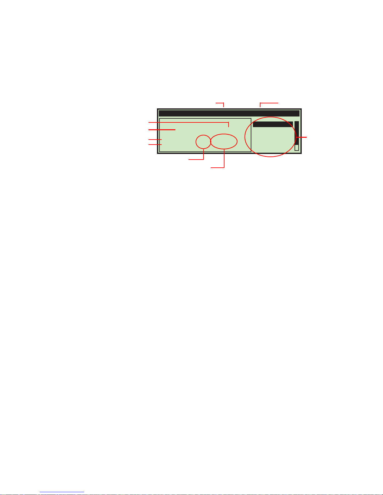
The Run screen
All of the basic Operator functions can be accessed right from the Run screen.
FIGURE 5: Run screen
Run screen information:
• The run screen will show overall counts.
• If batching is turned on, then batch count information will be shown.
Operating Instructions
• If the machine is a sort machine, then counts per bin will be shown.
• Exceptions will be shown on the run screen on machines that have the sort option
or anytime a print job is being run.
• If sorting is turned on, then an indicator will appear telling the operator which bin
is the primary and which is the secondary.
RUN
This selection will turn the motor on to process mail using the currently selected job
and operator.
CHANGE JOB
This selection will allow the operator to change the currently selected job. This
selection will not appear if there is only one job set up on the machine.
CHANGE OPER
This selection will allow another operator or the supervisor to be selected. Provisions
are made to password-protect the use of the supervisor functions. Operators can also
be optionally protected by password.
PRINT
In jobs that have printing enabled, this selection will be shown. This will allow the
operator to temporarily turn audit trail printing on and off. This capability was
provided in case there is an issue with the printer and the operator wants to run mail
without correcting that issue.
9Model 306 User Manual - OPEX Corporation
Page 12
Operating Instructions
In jobs that have printing enabled, this selection will also provide the operator with
the ability to clean the heads of the print cartridge. For more information, see
“Cleaning the Audit trail printer cartridge head” on page-52.
ZERO COUNT
This will allow the user to reset the statistics counters for the current run. At the
beginning of a run or at any point during a run, a user may reset the counters. This
will cause the software to zero all of the counts on the screen, close out the current
statistics “record,” and open up a new one.
STATISTICS
This will show the DISPLAY STATISTICS screen, which will allow the user to display and
optionally print their statistics on the reports printer, if purchased.
DISPLAY STATISTICS
Time Range: All times
VIEW DETAILS
PRINT DETAILS
PAPER FEED
FIGURE 6: Display Statistics screen
VIEW SUMMARY
PRINT SUMMARY
SET TIME RANGE
The operator can only view runs that were saved under their name. The choices are:
• VIEW DETAILS - Pulls together all jobs run by this operator in the specified time
range in their each individual view (example: if the operator ran 4 jobs, the data
will be pulled together into 4 views).
• VIEW SUMMARY - Pulls together all jobs run by this operator within the specified
time range in one view.
• PRINT DETAILS - provides a printout of the details described above. User must have
purchased the optional stats printer.
• PRINT SUMMARY - provides a printout of the summary described above. User must
have purchased the optional stats printer.
• SET TIME RANGE - allows operator to set specified date and time for pulling the
above information together.
More details of statistics can be found in the Statistics section of the Supervisor
Functions (“Supervisor Statistics” on page-45).
MY P ASSWORD
This will allow an Operator to change their password. See “Setting and Viewing
Operator Passwords” on page-17 for more information.
10 Model 306 User Manual - OPEX Corporation
Page 13
Staging the mail
Operating Instructions
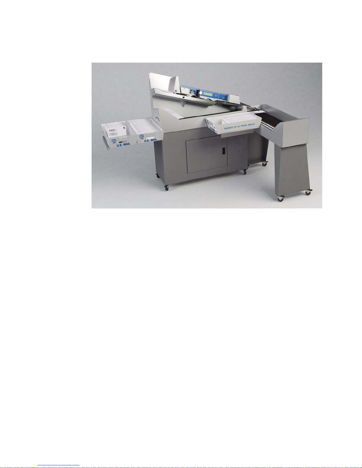
FIGURE 7: Model 306 with mail tray supports
The convenient mail tray supports may be used to hold U.S. Postal Service mail
trays. The integrated mail tray supports can be opened or closed depending on your
needs.
Preparing the mail
Very little preparation of the mail is required. Handfuls of mail can quickly be loaded
into the feed area. A simple tap to align the top or leading edge may be necessary
when loading mixed mail. Envelopes of different sizes and thicknesses can be run at
the same time.
11Model 306 User Manual - OPEX Corporation
Page 14
Operating Instructions
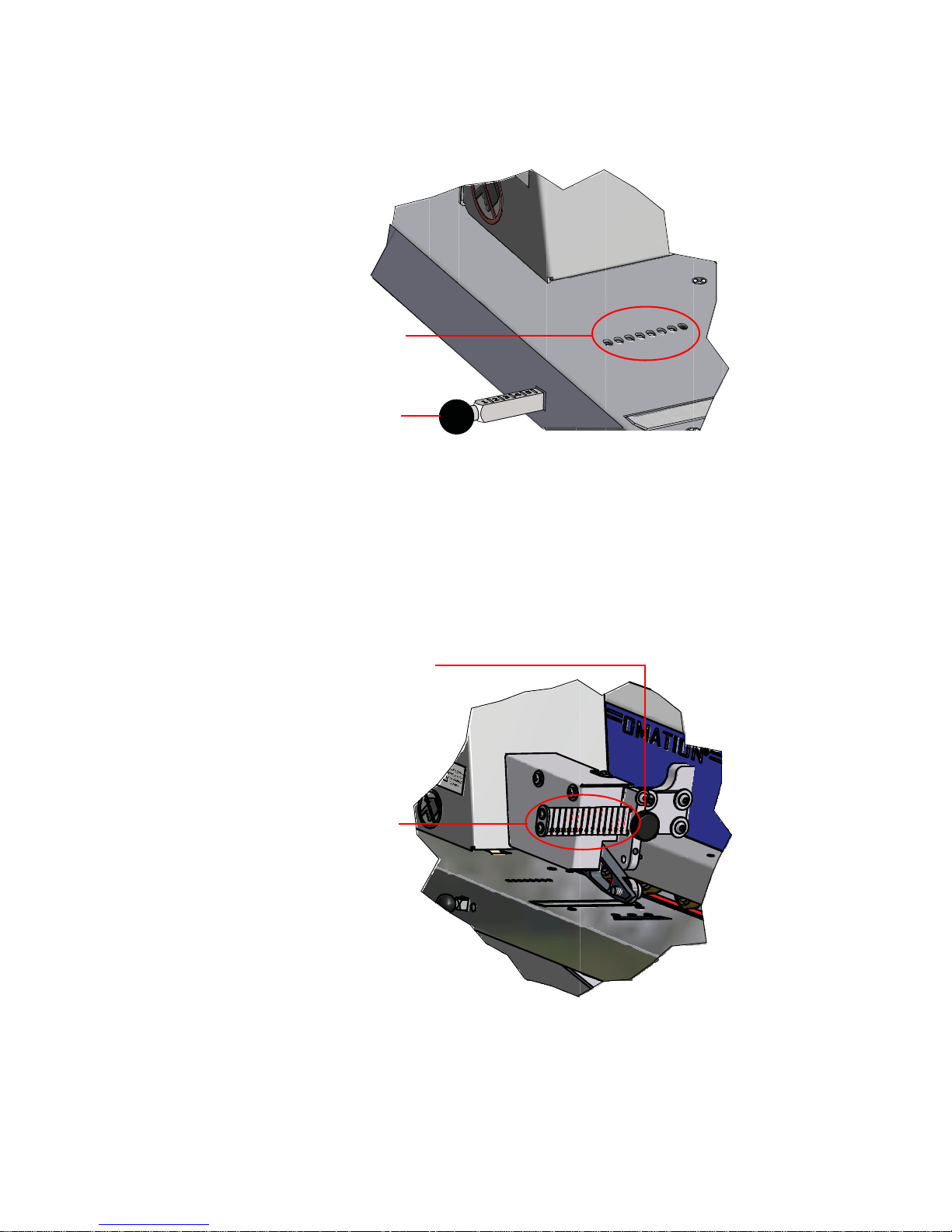
Height sensor location
Envelope height lever
Thickness detect thumbscrew
Position markers
are located here
Setting the Envelope Height position
FIGURE 8: Envelope height adjustment
The envelope height lever is used to set the position of the envelope height sensor.
When starting a job, you may see a screen telling you to verify or adjust the height
adjustment to a specific numbered position. Slide the lever in/out to set the correct
position. Use the numbered marks on the lever to set this position (refer to Figure 8).
Setting the Thickness Detect position
FIGURE 9: Thickness Detect adjustment
When starting a job, you may see a screen telling you to verify or adjust the
Thickness Detect to a specific numbered position. To make adjustments to the
12 Model 306 User Manual - OPEX Corporation
Page 15
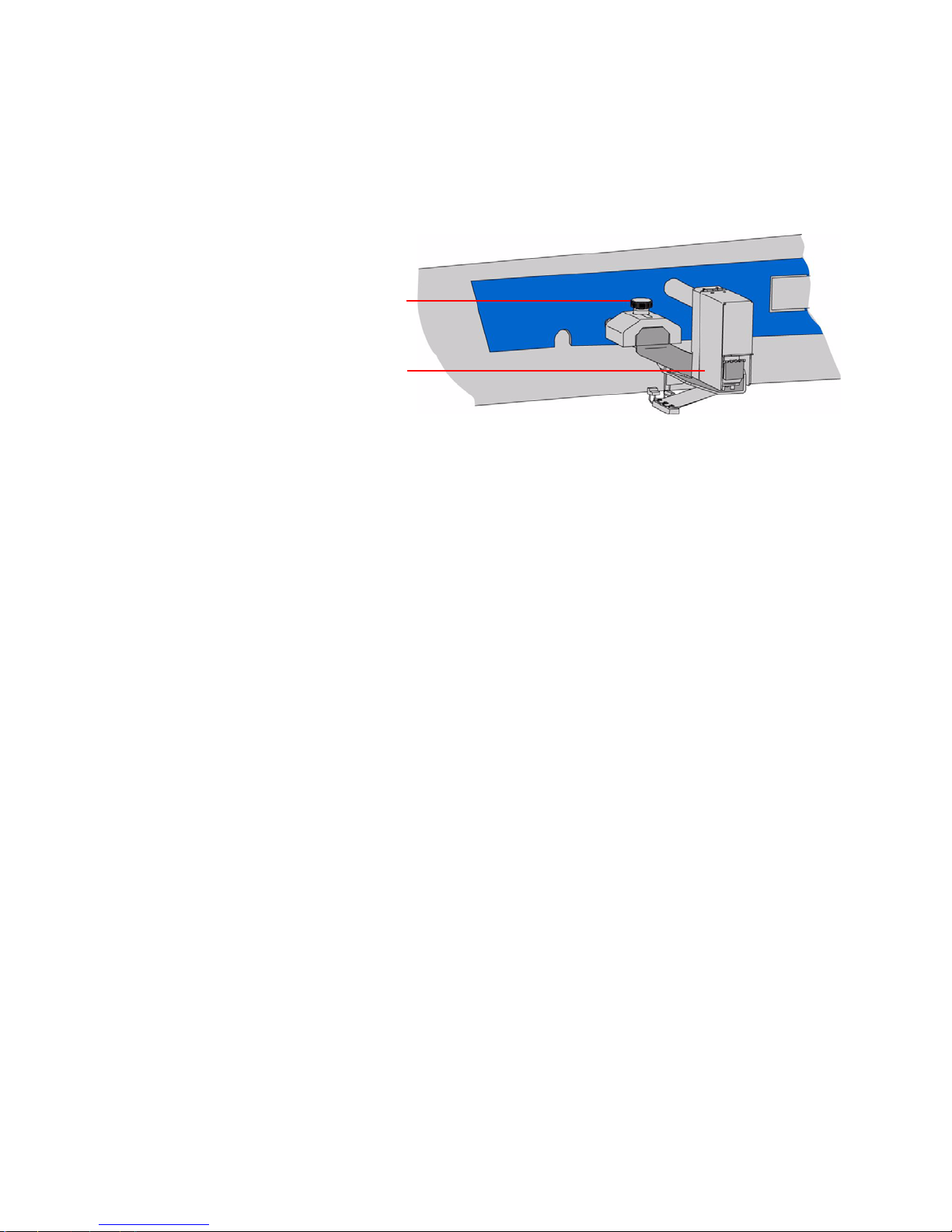
thickness detector, loosen the thumb screw (as shown in Figure 9), move the
Hi-Speed Inkjet Printer
assembly
Hi-Speed Inkjet Printer
thumbscrew
thickness detector in or out to the correct position, and tighten the thumbscrew.
Setting the Hi-Speed Inkjet Printer position
FIGURE 10: Hi-Speed Inkjet Printer adjustment
When starting a job, you may see a screen telling you to verify or adjust the Hi-Speed
Inkjet Printer to a specific numbered position. To make adjustments to the printer
position, loosen the thumb screw as shown in Figure 10. Then move the inkjet
printer assembly in or out to the desired position, and tighten the thumbscrew.
Operating Instructions
13Model 306 User Manual - OPEX Corporation
Page 16
Operating Instructions
Operating the Model 306
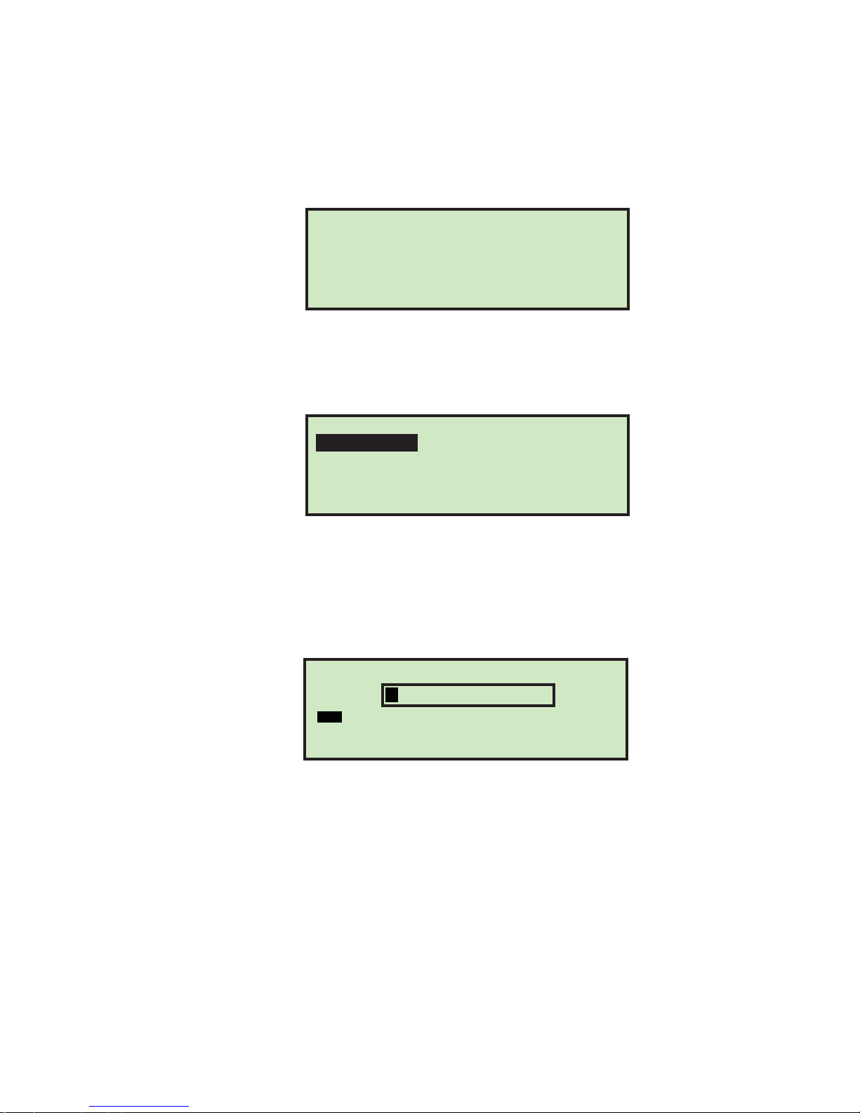
1 Make sure that the machine is plugged into an outlet.
2 Start the Model 306. If the information display is off, press the Start button. If
3 Press the Enter button. The SELECT OPERATOR screen appears.
passwords are enabled, the login screen will be displayed.
Friday, June 24, 2011 1:38 P.M.
MODEL 306
OPEX CORPORATION
Press ENTER to log in.
FIGURE 11: Login screen
If passwords are disabled, the run screen appears as shown in step 6.
SELECT OPERATOR
CHRIS NEW SUPERVISOR
FIGURE 12: Select Operator screen
4 Use the Arrow keys to highlight an operator and press the Enter button to select
the operator. If a password is required for the selected operator, the ENTER
PASSWORD screen will be displayed next (see Figure 13).If a password is not
required, skip to step 6.
ENTER PASSWORD
A B C D E F G H I J K L M
N O P Q R S T U V W X Y Z
0 1 2 3 4 5 6 7 8 9 Aa INS
OVRDEL < SAV
FIGURE 13: Enter Password screen
5 Use the Arrow keys and the Enter button to enter a password. An asterisk (*) will be
displayed in the password field for each character entered. Entering SAV will force
the software to check to see if the entered password matches the saved password.
If the correct password was entered, it is valid until the Stop button is pressed
(LCD off).
If you entered an incorrect password, the INCORRECT PASSWORD warning message is
displayed.
14 Model 306 User Manual - OPEX Corporation
Page 17
Operating Instructions
Selected operator
name appears here
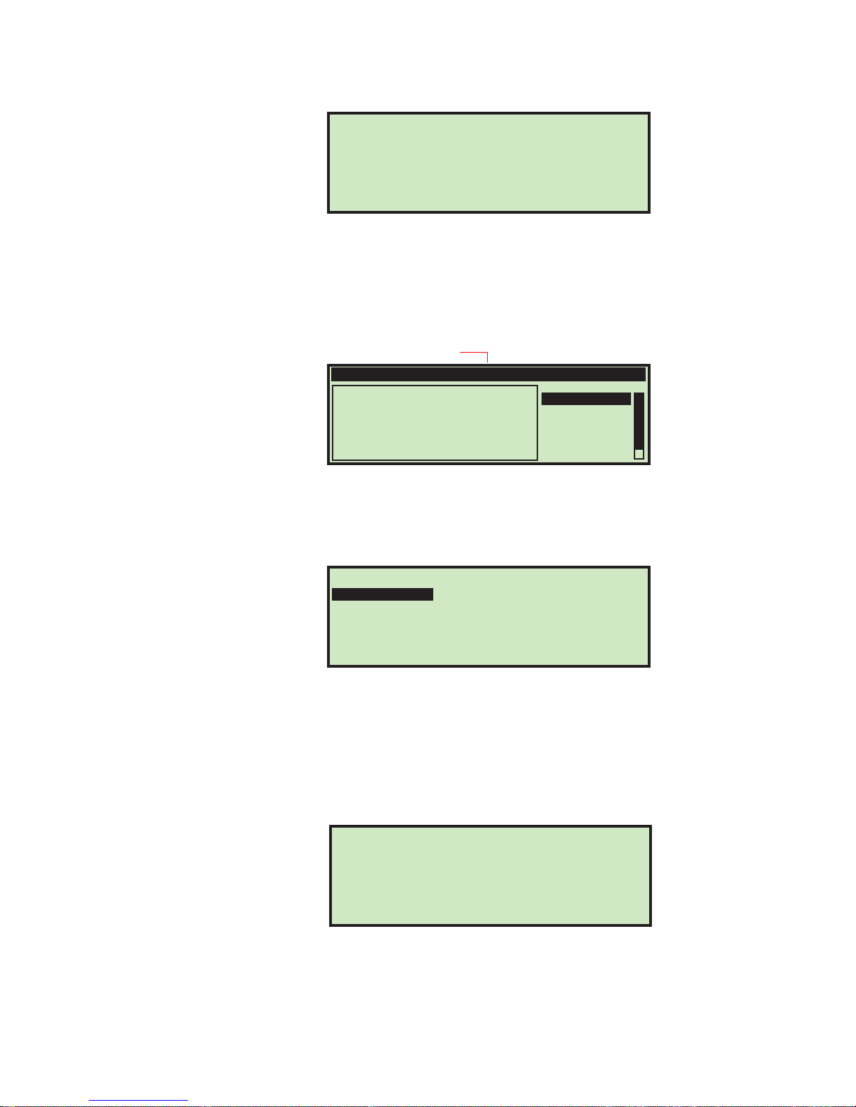
INCORRECT PASSWORD
Press any key to continue
FIGURE 14: Incorrect Password scree n
Pressing any button on the keypad will return you to the run screen.
6 If the password was entered correctly, or if passwords are disabled, the Run
screen is displayed with the newly-selected Operator.
OPERATOR:CHRIS JOB:TEST
RUN
00000
(S) SIDE 00000
(P) LOWER 00000
(E)00000
CHANGE JOB
CHANGE OPER
PRINT: OFF
ZERO COUNT
STATISTICS
FIGURE 15: Operator Main Menu screen (example)
7 Press the Up/Down arrow buttons to go to CHANGE JOB and press the Enter button.
The Select Job screen appears (Figure 16).
SELECT JOB
AMEX CREDIT MCARD
VISA NEW
FIGURE 16: Select Job screen
8 Use the Arrow buttons to choose a job, and press Enter to select it. The Run screen
is displayed - with the newly-selected job.
9 On the Run screen, use the Arrow buttons to navigate to RUN, and press Enter.
Based on the job settings, you may have additional information that appears on
the screen, such as the following example:
VERIFY OR ADJUST THE FOLLOWING:
CUTTER: POSITION 1
HI-SPEED INKJET PRINTER: POSITION 1
FIGURE 17: verification screen
10 Verify the adjustments needed for the selected job, and press Enter to start.
Press the ENTER button when ready.
15Model 306 User Manual - OPEX Corporation
Page 18

Operating Instructions
Stopping the machine
1 Press the Cancel button to stop the job and return to the Run screen. The Model
NOTE: While running the machine, you should watch trash levels and chip
“haystacking” to prevent backups that might jam the cutters and create a
service call.
306 will stop running the selected job. From time to time, the machine may stop
for jam control. If the machine stops, an error message will appear on the run
screen. Simply clear the visible jam and press Enter to restart the machine. Refer
to Table 5 on page-48 for a list of error messages.
16 Model 306 User Manual - OPEX Corporation
Page 19
Adjust LCD Contrast
The contrast level for the LCD display can be adjusted for optimal viewing.
1 Press the Stop button on the keypad so that the LCD is in the off state.
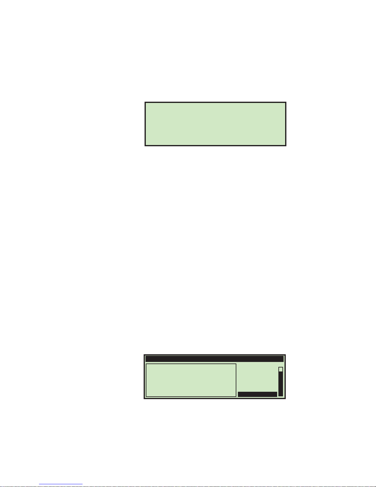
2 Press the Left arrow button. The Adjust Intensity screen appears (Figure 18).
FIGURE 18: Adjust Intensity screen
3 Use the Up or Down buttons to darken or lighten the display as desired. A
numerical value in the lower right corner of the display will indicate the display
setting. The value can range from 0 (lightest) to 255 (darkest).
4 Once the contrast level is set for optimal viewing, press Cancel to exit the Adjust
Intensity screen. Either the login screen is then displayed (if passwords are
enabled), or the run screen is displayed (if passwords are disabled).
Operating Instructions
OPEX CORPORATION
PUSHING THE ENVELOPE...
THROUGH THE 21ST CENTURY!
Use UP or DOWN to adjust intensity: 110
NOTE: If you should power up the Model 306 and the display does not appear to have
text, or if it looks solid black, it may simply be that the intensity has been
accidently set to either of its extreme positions. Try performing this
adjustment first before contacting Opex Tech Support for assistance.
Setting and Viewing Operator Passwords
The operator has the ability to set and reset their password. However, the operator
will need to enter his/her current password before the password can be reset. If a
password has not been previously entered, the user will not be prompted to enter
their current password before entering a new password. The supervisor also has the
ability to enable/disable operator passwords.
To change a password
1 After logging in, use the Arrow buttons to select MY P ASSWORD from the Run screen
to change the currently selected operator’s password.
OPERATOR:CHRIS JOB:TEST
00000
(S) SIDE 00000
(P) LOWER 00000
(E)00000
CHANGE JOB
CHANGE OPER
PRINT: OFF
ZERO COUNT
STATISTICS
MY PASSWORD
FIGURE 19: Run screen - select MY PASSWORD
2 Press Enter. The CHECK PASSWORD screen (Figure 20) will be displayed to remind the
operator that leaving the password blank will disable the password feature.
17Model 306 User Manual - OPEX Corporation
Page 20
Operating Instructions
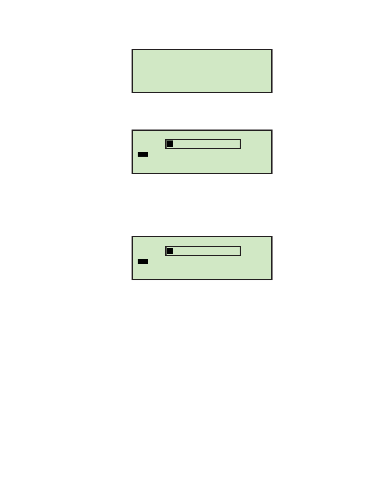
3 Press the Enter button to display the CURRENT PASSWORD screen.
4 The operator must enter their current password before setting their new
CHECK PASSWORD
To add or change password, press ENTER.
(Leaving the password blank disables
FIGURE 20: Check Password screen
A B C D E F G H I J K L M
N O P Q R S T U V W X Y Z
0 1 2 3 4 5 6 7 8 9 Aa INS
OVRDEL < SAV
FIGURE 21: Current Password screen
password. Use the keypad to enter the current password.
the password feature.)
CURRENT PASSWORD
Once the correct current password has been entered, the display automatically
changes to the NEW PASSWORD screen, allowing you to create a new password.
NEW PASSWORD
A B C D E F G H I J K L M
N O P Q R S T U V W X Y Z
0 1 2 3 4 5 6 7 8 9 Aa INS
OVRDEL < SAV
FIGURE 22: Enter Password screen
5 Enter the new password using the keypad. The password can be up to 10
characters in length. Selecting SAV will save the new password. The LCD will
return to the run screen after entering a password.
18 Model 306 User Manual - OPEX Corporation
Page 21
Supervisor Operations
The supervisor role is to manage Operators and Jobs. All of the supervisor tasks can
be launched from the supervisor main menu.
To access the Supervisor screen
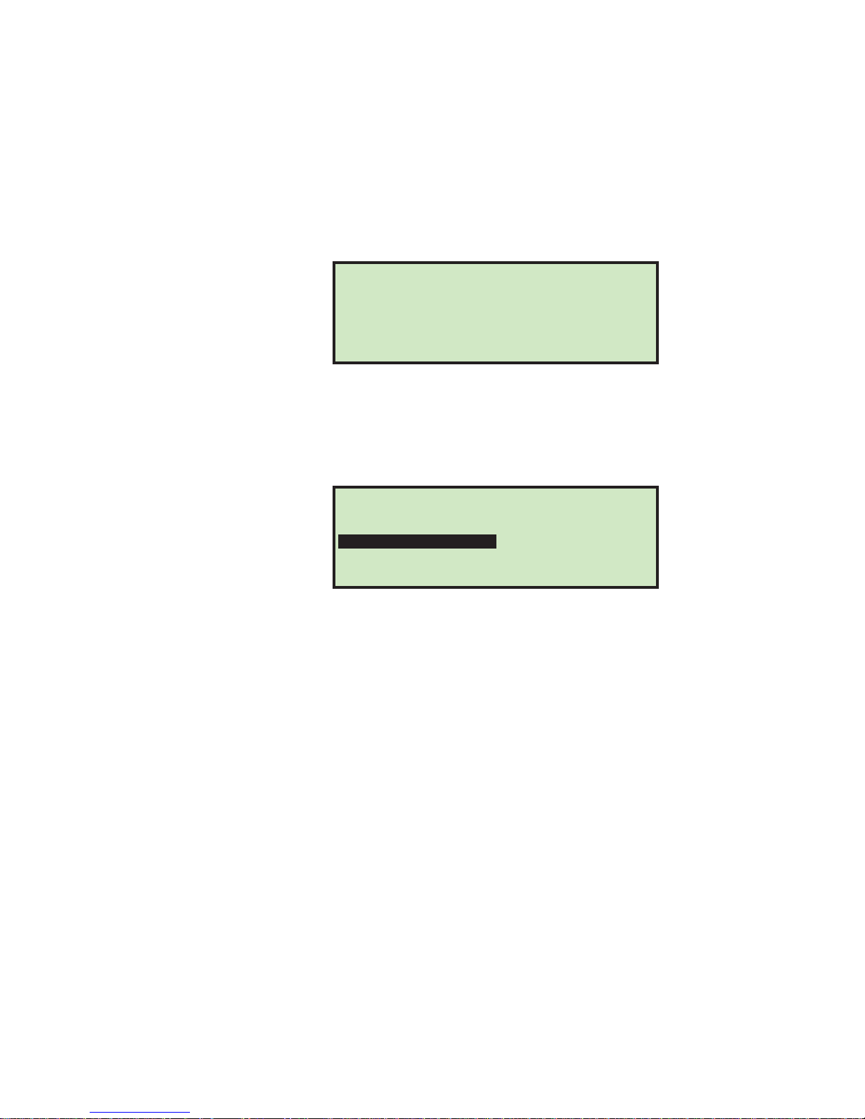
1 If the machine is off, press the Start button. The Login screen appears.
FIGURE 23: Login screen
2 Press Enter. The SELECT OPERATOR screen appears.
3 Use the arrow keys to select SUPERVISOR, and press Enter. The Supervisor screen
will be displayed.
Supervisor Operations
Friday, June 24, 2011 1:38 P.M.
MODEL 306
OPEX CORPORATION
Press ENTER to log in.
FIGURE 24: Supervisor screen
This screen is where all the supervisor tasks can be launched. The following tasks
can be performed:
- JOB MENU - add, modify and print jobs. Described on page-19.
- STATISTICS MENU - view and print statistical reports. Described on page-45.
- OPERATOR MENU - add, modify and print operators. Described on page-35.
- SYSTEM CONFIGURATION - view and update the system configuration parameters.
- AUDIT TRAIL MENU - view and update the audit trail parameters. Described on
- PASSWORD OPTIONS - globally enable or disable all passwords. Described on
Job Menu
Monday, July 20, 2011 9:11 A.M.
SUPERVISOR
JOB MENU
OPERATOR MENU
AUDIT TRAIL MENU
Details of these parameters are located on page-39.
page-40.
page-43.
STATISTICS MENU
SYSTEM CONFIGURATION
PASSWORD OPTIONS
A Supervisor has the ability to create and maintain a job list. A maximum of 100 jobs
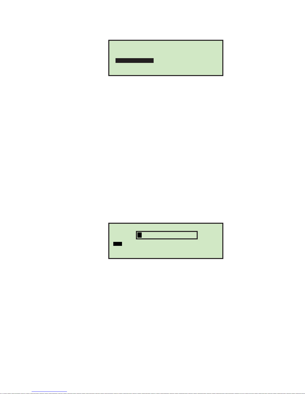
are supported. Selecting JOB MENU and pressing Enter will display the Job Menu
screen, and allow the supervisor to perform the following functions:
19Model 306 User Manual - OPEX Corporation
Page 22
Supervisor Operations
JOB MENU
FIGURE 25: Job menu screen
• ADD – enter a new job and setup the job options.
• DELETE - select a job from the job list and delete the job.
• MODIFY – select an existing job from the job list and modify the job’s options.
• COPY - select an existing job from the job list and make a new job based on the
• SORT LIST – alphabetically sort the job list.
• PRINT – select a job from the job list and print all parameters associated with the
• PRINT ALL - print the entire list of jobs (available when stats printer option is
Add Job
The supervisor has the ability to create a new job.
ADD
MODIFY
SORT LIST
PRINT ALL
DELETE
COPY
PRINT
existing job parameters. Parameters for the new (copied) job can also be edited.
selected job (available when stats printer option is purchased).
purchased).
1 On the Job Menu screen (Figure 25), select ADD, and press Enter. The RENAME JOB
screen appears as shown.
RENAME JOB
A B C D E F G H I J K L M
N O P Q R S T U V W X Y Z
0 1 2 3 4 5 6 7 8 9 Aa INS
OVRDEL < SAV
FIGURE 26: Rename Job screen
2 Enter the new job name using the Arrow buttons to navigate through the
onscreen keypad. Selecting SAV will create the new job. Pushing the Cancel button
on the keypad will end the job creation process.
Once you have named the job and selected SAV, the following screen appears as
shown in Figure 27.
20 Model 306 User Manual - OPEX Corporation
Page 23
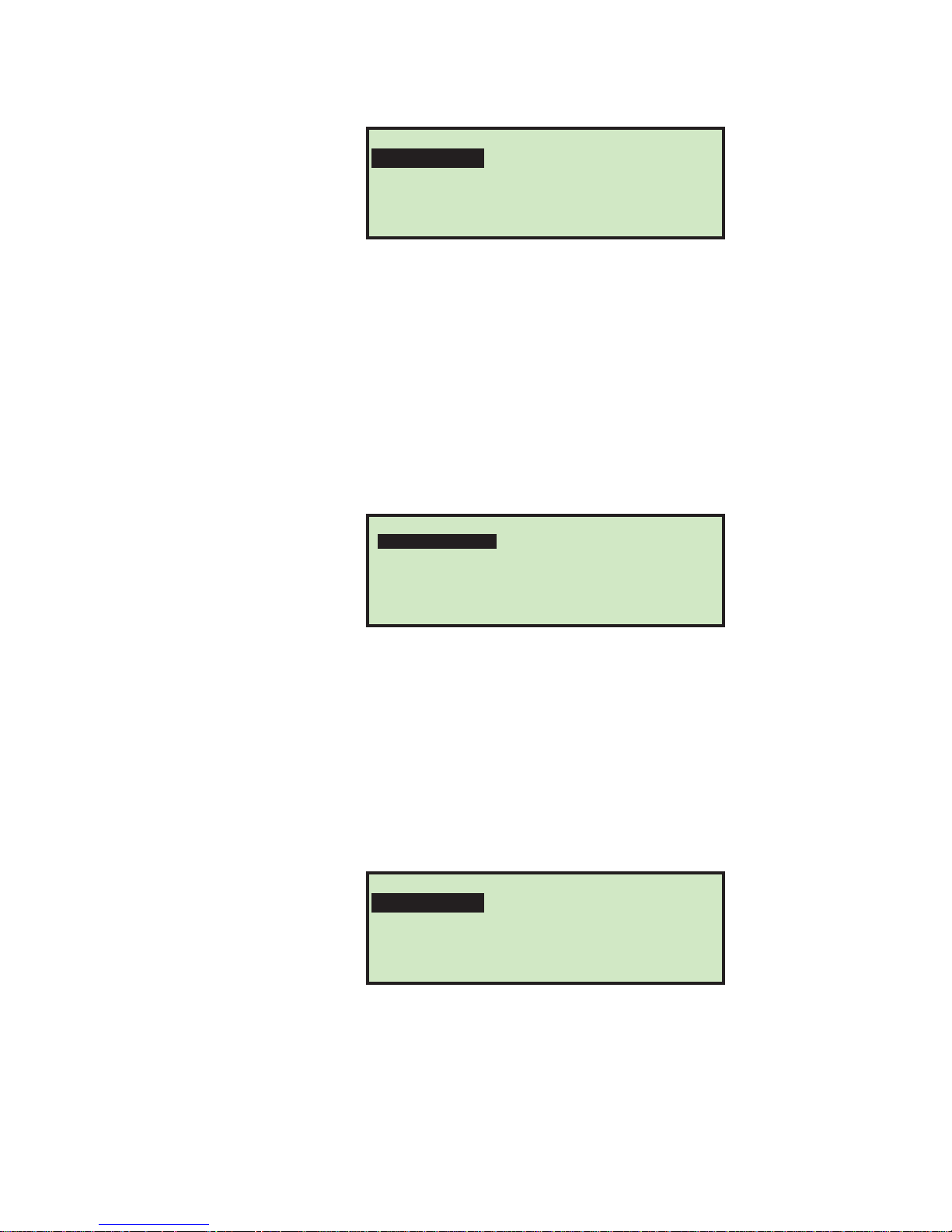
FIGURE 27: Place Cursor Over New Location (job) screen
3 Place the cursor over an existing job and press Enter to place the job in the list. The
new job will be placed after the selected job, and the JOB SETUP screen appears.
For details on the Job Setup screen, see “Modify Job” on page-21.
Delete Job
The supervisor can select a job from the job list and delete it.
1 On the Job Menu screen (Figure 25), select DELETE. The SELECT JOB TO DELETE
screen appears as shown.
Supervisor Operations
PLACE CURSOR OVER NEW LOCATION
TEST JOB NEW
FIGURE 28: Select Job to Delete screen
2 Use the Arrow keys to choose a job, and press Enter to delete the job. The job will
be deleted, and the display will return to the JOB MENU screen.
Modify Job
The MODIFY job selection allows the supervisor to edit an existing job.
1 On the Job Menu screen (Figure 25), select MODIFY. The SELECT JOB TO MODIFY
screen appears.
SELECT JOB TO DELETE
AAA
MCARD
TEST JOB AMEX001 NEW
AMEX
NEW
SELECT JOB TO MODIFY
VISA
FIGURE 29: Select Job to Modify screen
2 Use the Arrow keys to choose a job, and press Enter to select the job. The job will
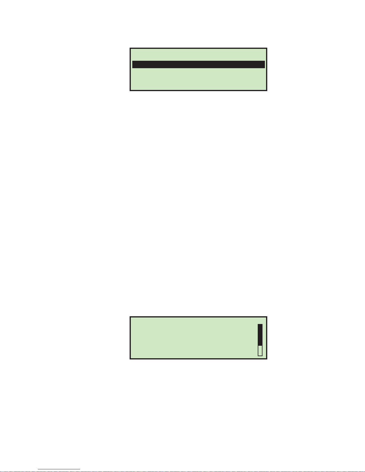
be deleted, and the display will return to the JOB MENU screen. The JOB SETUP
screen will be displayed (Figure 30).
21Model 306 User Manual - OPEX Corporation
Page 24
Supervisor Operations
FIGURE 30: Job Setup screen
The job setup options are described below.
Sort Wizard
This selection should be used when creating a job that involves sorting by thickness,
or by length. The sort wizard will set various machine parameters for the user based
upon answers to questions and data that is collected when mail is run. The sort
wizard can also be used to set height parameters.
The user should have an idea how they would like to sort their mail into two piles
using any combination of length, height or thickness. The user must also have a
good selection of primary mail that will be representative of the full range (that is, it
contains some of the thinnest and thickest mail that they would like to go into the
primary pile). For more information on the Sort Wizard see, “SORT WIZARD” on
page-23.
JOB SETUP
SORT WIZARD
JOB OPTIONS
VIEW LENGTH DATA
VIEW THICKNESS DATA
Job Options
This selection will allow the supervisor to modify any existing jobs. Parameters will
be shown on a screen in the order shown in “Model 306 Job Parameters” on page-32.
Most parameters can be set based on expected results, such as printing or no
printing, for example. The length data and thickness readings are obtained by
running the job with the length and/or thickness parameters wide open, and then
viewing the data using the provided screens detailed below.
View Length Data
Selecting this option displays the LENGTH HISTOGRAM screen.
LENGTH:621
LENGTH:625
LENGTH:626
LENGTH:627
LENGTH:628
LENGTH:629
LENGTH:630
FIGURE 31: Length Histogram screen
This screen shows the length measurements. The data is stored in a buffer of 599
counters representing 400-999. When a piece is run, the software will update the
appropriate counter (i.e., a length of 700 will increment the 300th counter). The
display software will show the first 50 non-zero counters. Once a counter reaches
255, it will stop incrementing.
LENGTH HISTOGRAM
COUNT: 1
COUNT: 1
COUNT: 4
COUNT: 5
COUNT: 5
COUNT: 4
COUNT: 3
22 Model 306 User Manual - OPEX Corporation
Page 25
View Thickness Data
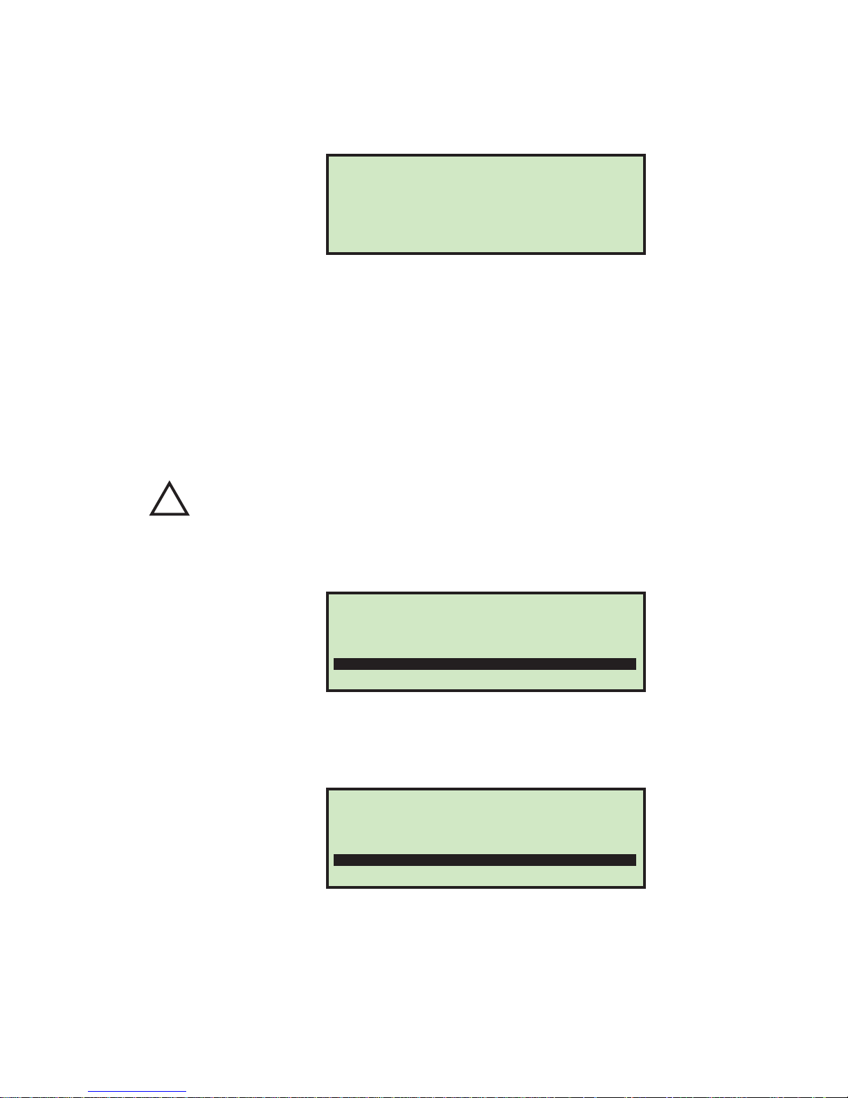
!
Selecting this option displays the THICKNESS HISTORY screen.
Supervisor Operations
FIGURE 32: Thickness History screen
This screen displays the output of the average thickness algorithm. The data is
stored in a buffer of 256 byte counters representing calculations of 0 to 255. When a
piece is run, the software will update the appropriate counter (i.e., an average
thickness of 32 will increment the 32nd counter). The display software will show the
first 50 non-zero counters. Once a counter reaches 255, it will stop incrementing.
SORT WIZARD
The Sort Wizard is used to configure a sorting job.
Caution:
1 From the Supervisor > Job Setup screen (Figure 30), select SORT WIZARD, and press
Enter. The sort wizard will start out by asking three questions that must be
answered. The first asks if you want to sort on thickness as shown below.
THICKNESS: 22
THICKNESS: 26
THICKNESS: 27
THICKNESS: 28
THICKNESS: 29
THICKNESS: 32
THICKNESS: 33
THICKNESS HISTORY
COUNT: 1
COUNT: 7
COUNT: 7
COUNT: 17
COUNT: 2
COUNT: 1
COUNT: 2
When running, the Sort Wizard will modify the job to perform its functions. If the user
presses the Stop button or power is killed in the middle of a sort wizard setup, the job
will not be properly restored to its original state.
SORT MAIL BASED ON THICKNESS?
NO
YES
FIGURE 33: Sort Mail Based On Thickness screen
2 Use the Arrow buttons to select either NO or YES, and press Enter. The second
question asks if you want to sort on length as shown below.
SORT MAIL BASED ON LENGTH?
NO
YES
FIGURE 34: Sort Mail Based On Length screen
3 Use the Arrow buttons to select either NO or YES, and press Enter. The third
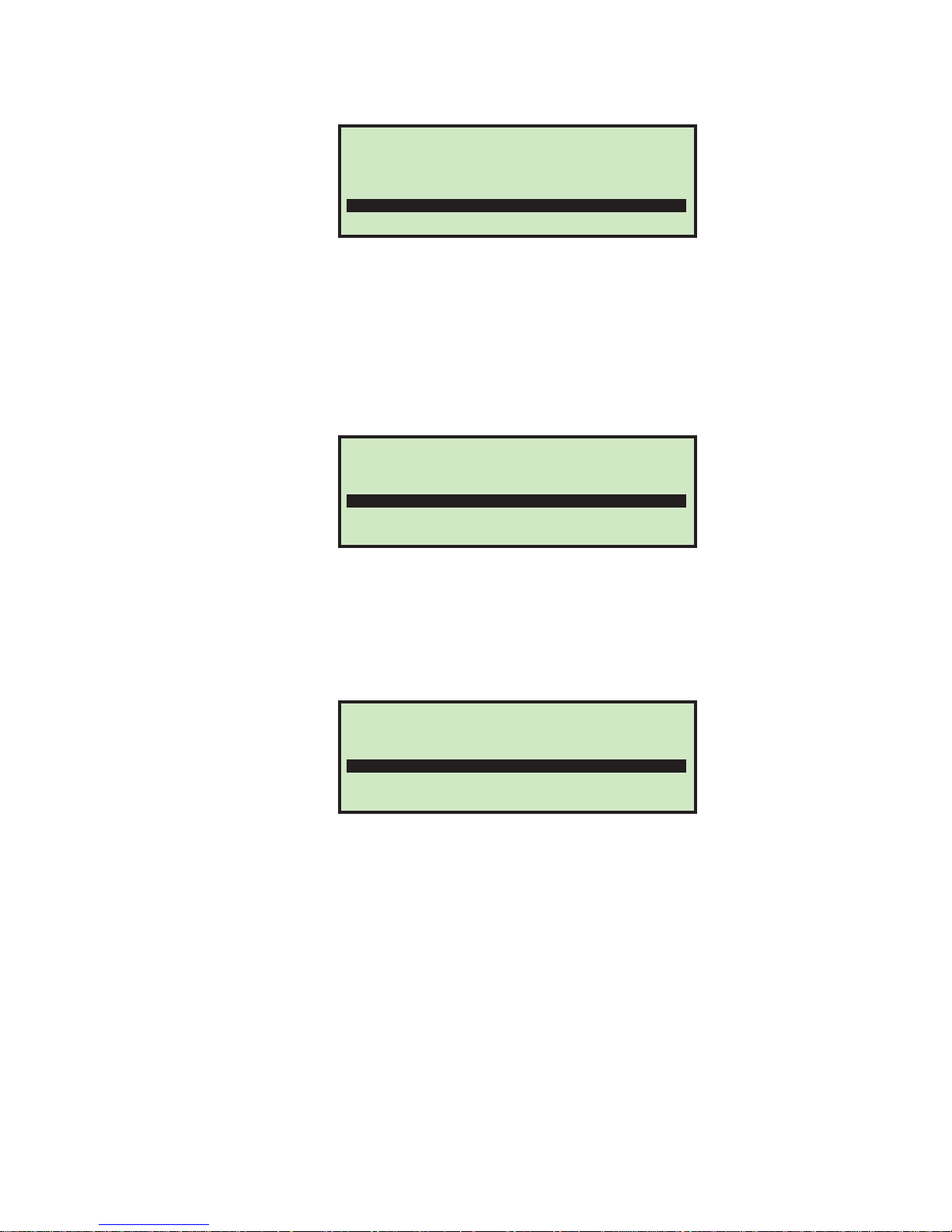
question asks if you want to sort on height as shown below.
23Model 306 User Manual - OPEX Corporation
Page 26
Supervisor Operations
4 Use the Arrow buttons to select either NO or YES, and press Enter.
NOTE: If the user answers NO to all of the above, the job will be set accordingly and
5 If one or more of the above was answered YES, then the wizard asks where you
SORT MAIL BASED ON HEIGHT?
NO
YES
FIGURE 35: Sort Mail Based On Height screen
the message SORT WIZARD COMPLETED will be displayed. This job will obviously
not be set to sort mail.
would like the primary mail sorted to.
SORT PRIMARY MAIL TO:
LOWER
SIDE
FIGURE 36: Sort Primary Mail To screen
6 This screen is used to select the area where the primary mail will be sent. Use the
Arrow buttons to select either LOWER or SIDE, and press Enter.
7 If sorting on thickness, the wizard will ask the following question regarding
thickness values.
COMPARED TO THE PRIMARY MAIL,
THE SECONDARY MAIL IS:
THINNER
THICKER
BOTH THINNER AND THICKER
FIGURE 37: Compared To Primary Mail, The Secondary Mail Is (thickness) screen
8 Use the Arrow buttons to make a selection, and press Enter. Choices are: THINNER,
THICKER or BOTH THINNER AND THICKER.
This question is being asked to help the wizard set the minimum and maximum
thickness values. If THINNER is selected, then the maximum will be set to the
highest valid setting and minimum will be set after the sample set of primary mail
is run. If THICKER is selected, then the minimum will be set to the lowest valid
setting and maximum will be set after the sample set of primary mail is run. If
both are selected, then minimum and maximum will be set after sample set is
run.
9 If sorting on length, the wizard will ask the following questioni regarding length
values.
24 Model 306 User Manual - OPEX Corporation
Page 27
Supervisor Operations
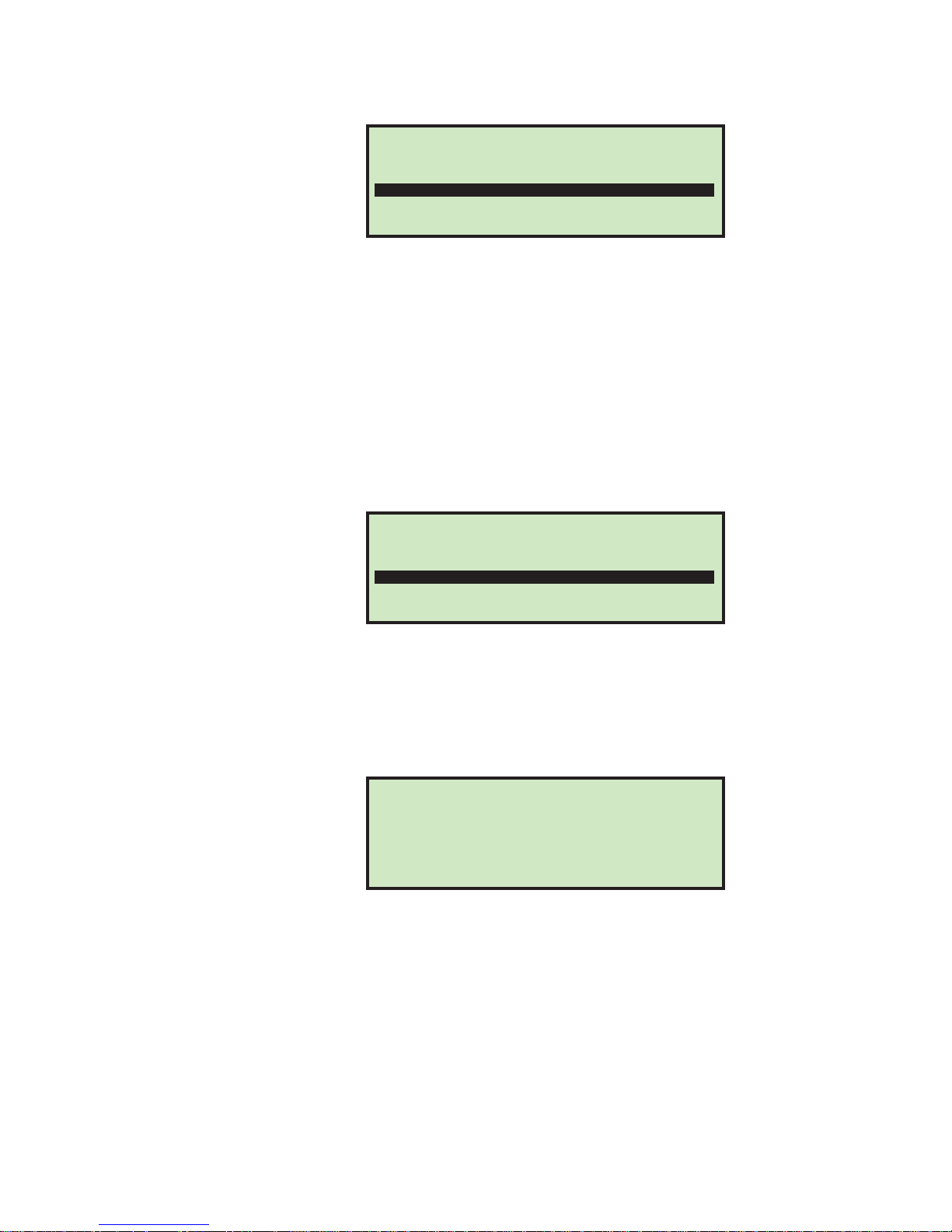
COMPARED TO THE PRIMARY MAIL,
THE SECONDARY MAIL IS:
SHORTER
LONGER
BOTH SHORTER AND LONGER
FIGURE 38: Compared To Primary Mail, The Secondary Mail Is (length) screen
10 Use the Arrow buttons to make a selection, and press Enter. Choices are: SHORTER,
LONGER or BOTH SHORTER AND LONGER.
This question is being asked to help the wizard set the minimum and maximum
length values. If SHORTER is selected, then the maximum will be set to the highest
valid setting and minimum will be set after the sample set of primary mail is run.
If LONGER is selected, then the minimum will be set to the lowest valid setting and
maximum will be set after the sample set of primary mail is run. If both are
selected, then minimum and maximum will be set after sample set is run.
11 If sorting on height, the wizard will ask how the height sensor will respond when it
is blocked by an envelope.
WHEN AN ENVELOPE BLOCKS THE HEIGHT
SENSOR, THE HEIGHT SENSOR WILL ?
FAIL
PASS
FIGURE 39: When An Envelope Blocks The Height Sensor, The Height Test Will screen
12 Use the Arrow buttons to make a selection, and press Enter. Choices are: FAIL or
PASS. This question is being asked to help set the WHEN HEIGHT BLOCKED job
parameter. For more details, see “SORT ON HEIGHT” on page-33.
13 Once these questions are answered, the following informational screen appears:
PLACE REPRESENTATIVE SAMPLE OF
PRIMARY MAIL IN FEEDER TO CATEGORIZE.
SAMPLE SHOULD INCLUDE MAIL THAT
IS CONSIDERED PROPER HEIGHT, LENGTH
AND THICKNESS. ADJUST TMD OR HEIGHT
DETECT SENSOR TO ENSURE PROPER READINGS.
PLACE CUTTER IN NO-CUT POSITION.
PRESS ENTER TO CONTINUE.
FIGURE 40: Sort Wizard information screen
14 Once the tasks on the screen have been accomplished, press Enter. The Sort
Wizard run screen appears.
25Model 306 User Manual - OPEX Corporation
Page 28

Supervisor Operations
SORT WIZARD JOB:TEST
0032
THICKNESS: 023 022 032
LENGTH: 625 624 634
HEIGHT: *
FIGURE 41: Sort Wizard run screen
MIN MAX
RUN
CLEAR
CONTINUE
CANCEL
PROFILES
15 Here the user can run their primary mail, which will provide the Sort Wizard with
information to set the parameters in the job. This screen will:
- Show counter of mail run.
- Appropriately show thickness information including thickness reading of last
piece, minimum reading and maximum reading.
- Appropriately show length measurement information including length
measurement of last piece, minimum reading and maximum reading.
- Appropriately show height indicator, which can be either PASS or FAIL.
- Provide the user with the ability to RUN, CLEAR, CONTINUE and CANCEL.
RUN - will allow the user to run mail for the purpose of collecting job parameter
information.
CLEAR - provides the user with the ability to clear all of the collected data,
essentially starting over. This can be used if secondary mail was accidently run or
the user noticed double feeds were occurring.
CONTINUE - will take the user to the next screen of the sort wizard.
CANCEL - will take the user back to the screen they were at when they started the
sort wizard.
- When running mail, all jam control software will be activated as if it were a
regular run. The exception is double feed detection will not be active.
- All mail will be sent to the primary destination.
- User is responsible for ensuring mail does not double feed, as double detect
requires valid length and/or thickness maximums to be properly set.
- The sort wizard does not provide the ability to set all job parameters. The user
will still need to set all parameters which are not related to thickness, length
and/or height.
- If thickness sorting is turned on, the thickness parameters are set based on
the answer to the following Sort Wizard question:
TABLE 1: COMPARED TO PRIMARY MAIL, THE SECONDARY MAIL IS:
If set to: Then:
THINNER
THICKER
BOTH THINNER AND THICKER
Thickness minimum is set to the minimum collected value,
maximum is set to the highest valid setting.
Thickness minimum is set to the lowest valid setting,
maximum is set to the highest collected value.
Thickness minimum is set to the lowest collected value,
maximum is set to the highest collected value.
26 Model 306 User Manual - OPEX Corporation
Page 29
Supervisor Operations
- If length sorting is turned on, the length parameters are set based on the
answer to the following Sort Wizard question:
TABLE 2: COMPARED TO PRIMARY MAIL, THE SECONDARY MAIL IS:
If set to: Then:
SHORTER
LONGER
BOTH SHORTER AND LONGER
Length minimum is set to the minimum collected value,
maximum is set to the highest valid setting.
Length minimum is set to lowest valid setting, maximum is
set to the highest collected value.
Length minimum set to lowest collected value, maximum is
set to the highest collected value.
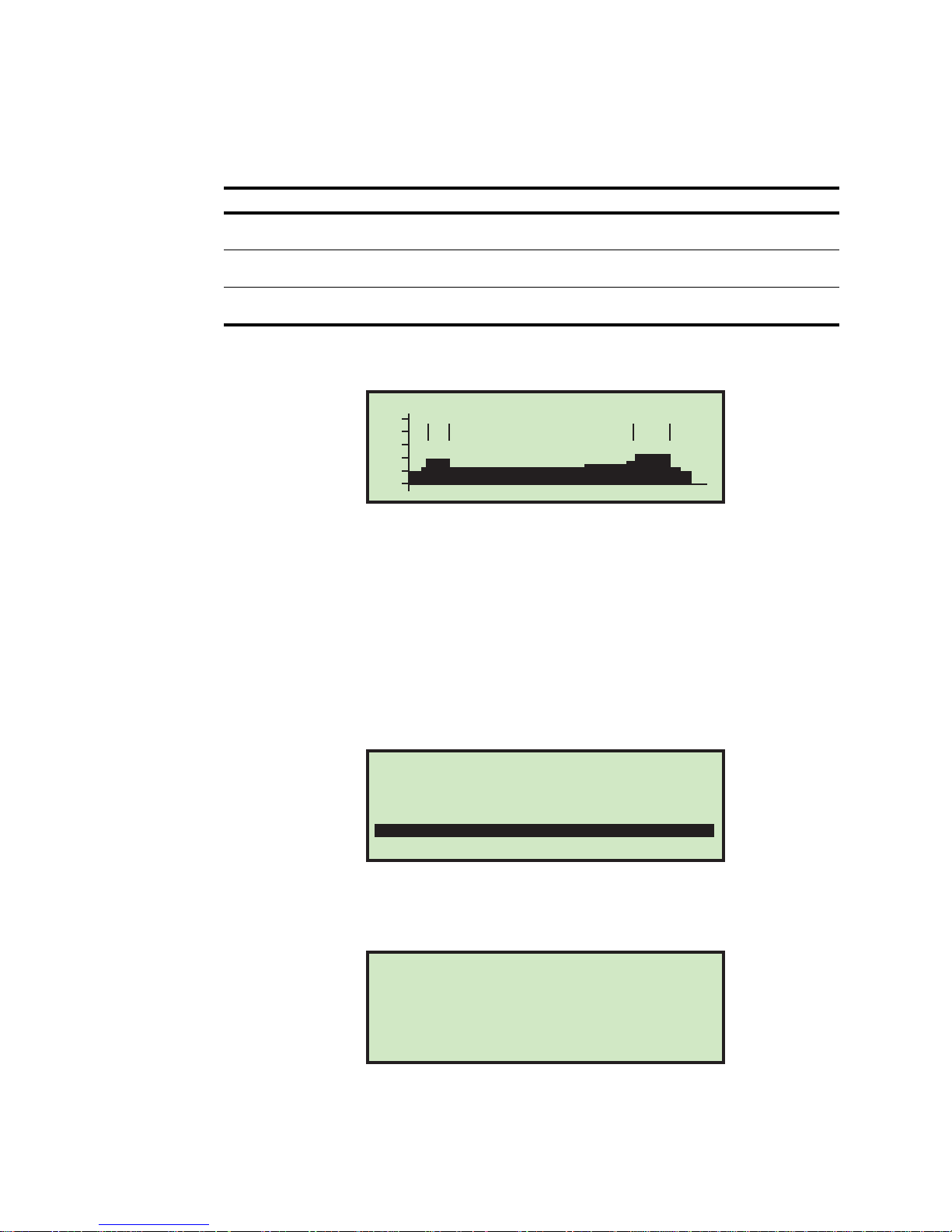
PROFILES - selecting this option will display a graph of each piece run.
250
200
150
100
AVG THICKNESS 28 PIECE ID:6
50
0
USE ARROW KEYS TO VIEW PROFILES
FIGURE 42: Thickness Profiles screen
Press the arrow keys to view the thickness profile for each of the pieces run in the
Sort Wizard test. Press Cancel to return to the Sort Wizard run screen.
THICK. DATA - Selecting this option displays the THICKNESS HISTORY screen, as
described in “View Thickness Data” on page-23.
LENGTH DATA - Selecting this option displays the LENGTH HISTOGRAM screen, as
described in “View Length Data” on page-22.
16 Selecting CONTINUE and pressing Enter will display the following screen asking if
you would like to test the sort scheme.
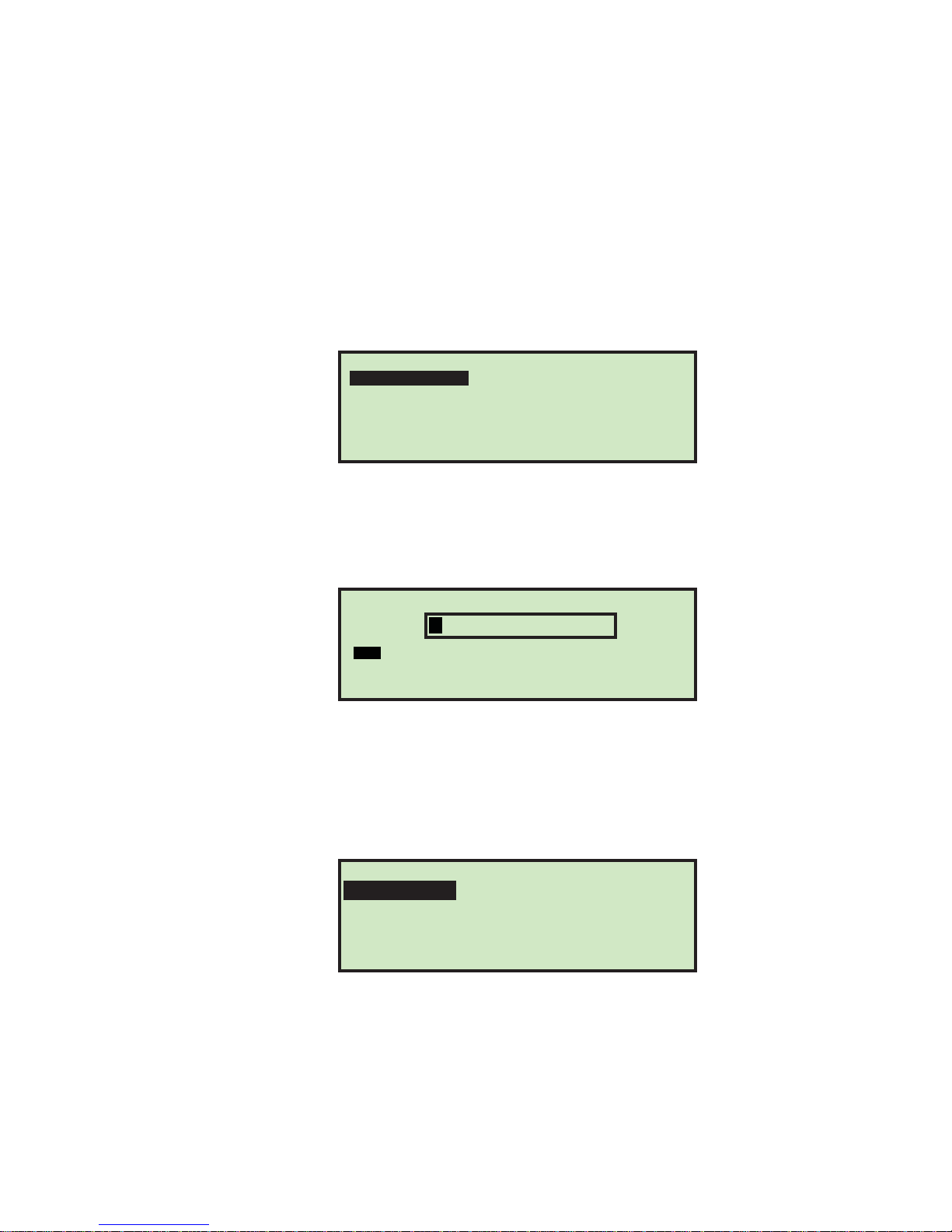
WOULD YOU LIKE TO TEST THE SORT SCHEME
BY RUNNING A SAMPLE OF MAIL?
NO
YES
FIGURE 43: Confirmation run screen
17 If you select YES, an informational screen is displayed,as shown below.
FIGURE 44: Informational screen
PLACE MAIL IN FEEDER AND PRESS ENTER.
MAIL WILL BE SORTED BASED ON THE SORT
SCHEME. IF THE MAIL IS SORTED INCORRECTLY
RE-RUN SORT WIZARD OR ADJUST SORT
PARAMETERS IN THE JOB PARAMETER
SCREEN.
PRESS ENTER TO CONTINUE.
27Model 306 User Manual - OPEX Corporation
Page 30
Supervisor Operations
18 Press Enter to complete the confirmation run. Make any adjustments to the job
Copy Job
This option allows you to select an existing job from the job list and make a new job
based on the existing job parameters. Parameters for the new (copied) job can also be
edited.
1 On the Job Menu screen (Figure 25), select COPY, and press Enter. The SELECT JOB
parameters as needed.
TO COPY screen appears.
AAA
MCARD
FIGURE 45: Select Job To Copy screen
SELECT JOB TO COPY
AMEX
NEW
VISA
2 Use the Arrow buttons to select an existing job, and press Enter. The RENAME JOB
screen appears.
RENAME JOB
A B C D E F G H I J K L M
N O P Q R S T U V W X Y Z
0 1 2 3 4 5 6 7 8 9 Aa INS
OVRDEL < SAV
FIGURE 46: Rename Job screen
3 Enter the new job name using the Arrow buttons to navigate through the
onscreen keypad. Selecting SAV will create the new job. Pushing the Cancel button
on the keypad will end the job creation process.
Once you have named the job and selected SAV, the following screen appears.
PLACE CURSOR OVER NEW LOCATION
TEST JOB NEW
FIGURE 47: Place Cursor Over New Location (job) screen
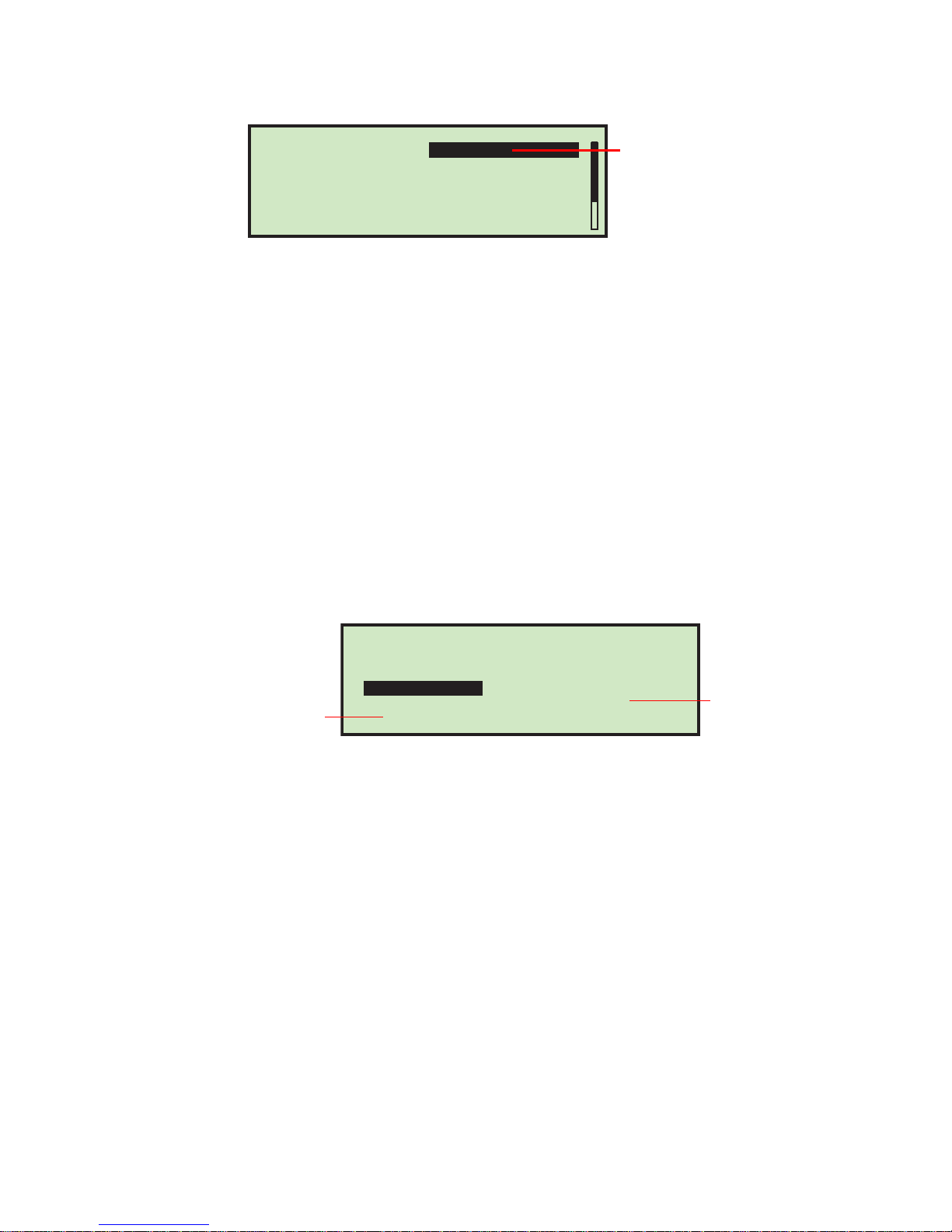
4 Place the cursor over an existing job and press Enter to place the job in the list. The
new job will be placed after the selected job, and the SELECT JOB OPTION screen
appears.
28 Model 306 User Manual - OPEX Corporation
Page 31
Supervisor Operations
New Job Name
Parameter settings are copied from
the existing job, but they are separate
from the existing job, and can be edited
for the new job.
JOB MENU
DELETE
COPY
PRINT
ADD
MODIFY
SORT LIST
PRINT ALL
Selects an individual job,
and prints all parameters
associated with it
Prints the entire
list of all jobs
JOB NAME
SELECT JOB OPTION
SORT ON THICKNESS
SORT ON LENGTH
SORT ON HEIGHT
GATE BATCHING
BATCH SIZE LOWER
EXCEPTION THRESHOLD
COPY JOB
NO
NO
NO
NO
DISABLED
5
FIGURE 48: Select Job Option screen
5 Use the Up/Down arrows to highlight a job parameter, and press Enter to select it.
The available job parameters are described on page-31.
Sort List
1 On the Job Menu screen (Figure 49), select SORT LIST.
2 Selecting SORT LIST will alphabetically sort the job list.
Print All Jobs or Individual Job Parameters
Job Information can be printed out for a single job or all jobs (available with stats
report printer option). The printout includes the job name and all job parameters (see
Figure 50). The user must be logged in as a supervisor to printout the report. The
print choices are available on the Job Menu screen.
FIGURE 49: Job Menu screen
NOTE:
If you want to print information for a specific job, you will be presented with
an additional screen where you can choose the job.
29Model 306 User Manual - OPEX Corporation
Page 32

Supervisor Operations
MODEL 306S
JOB PARAMETERS
OPEX
JOB NAME
SORT ON THICKNESS
SORT ON LENGTH
SORT ON HEIGHT
GATE BATCHING
BATCH SIZE LOWER
EXCEPTION THRESHOLD
CUT DEPTH
STAMP ORIENTATION
PRINTER JOB
PARAMETER DESCRIPTION
VISA
NO
NO
NO
NO
21
5
1
ANY DIRECTION
NO PRINT
VAL UE
PRINTED: JULY 1, 2011 11:30 A.M.
FIGURE 50: Example printout of Job information
30 Model 306 User Manual - OPEX Corporation
Page 33
Job Parameters
This section describes the job parameters that can be set for each job. The visibility
of certain job parameters are turned on/off to help the user. Job parameters can be
accessed when adding a new job, as described in “Add Job” on page-20, as well as
when modifying an existing job (described below).
To edit job parameters for an existing job
1 Login as a Supervisor.
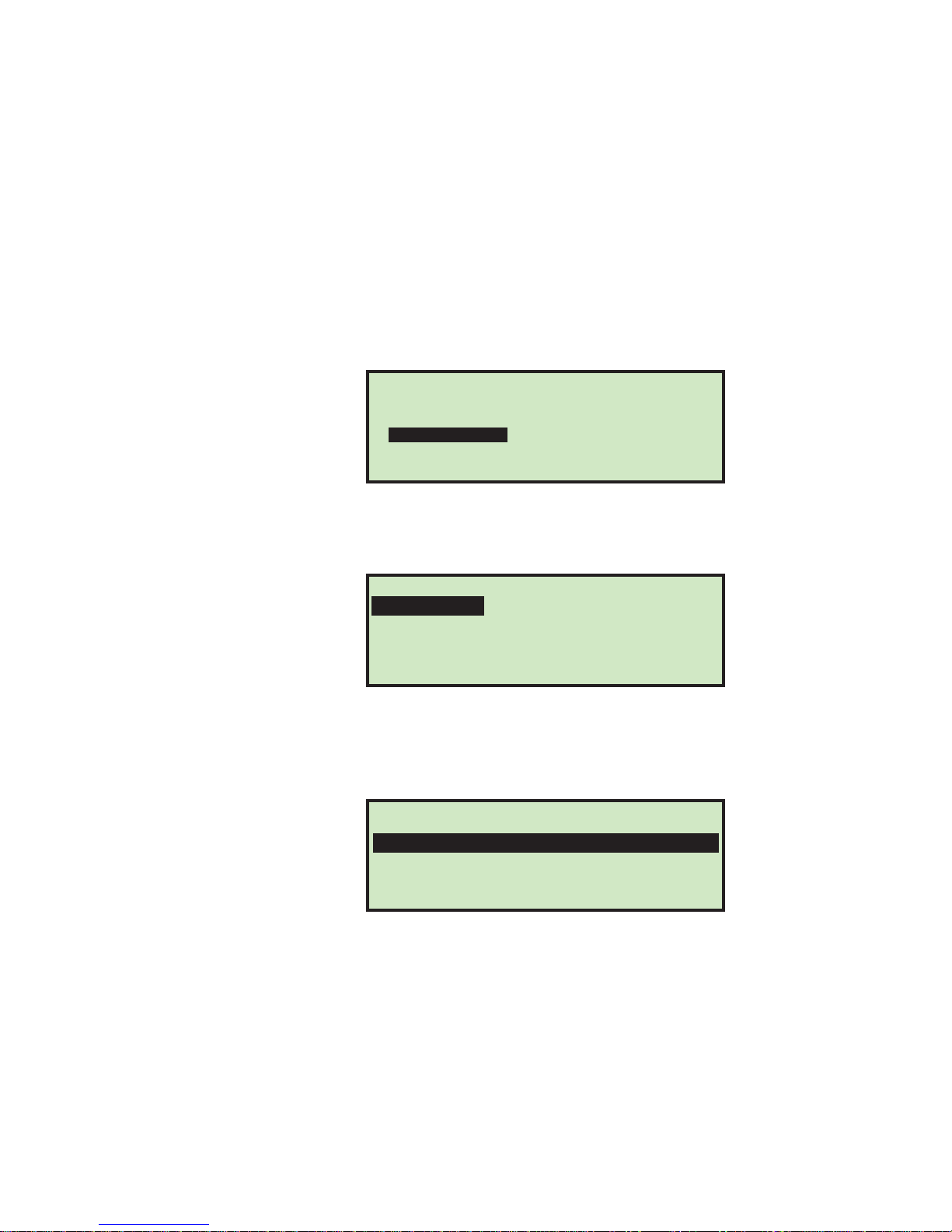
2 On the SUPERVISOR screen (see Figure 24), use the arrows to select JOB MENU and
press Enter. The Job Menu screen appears.
Job Parameters
JOB MENU
ADD
MODIFY
SORT LIST
PRINT ALL
FIGURE 51: Job Menu screen
DELETE
COPY
PRINT
3 Select MODIFY, and press Enter. The SELECT JOB TO MODIFY screen appears.
SELECT JOB TO MODIFY
TEST JOB AMEX001 NEW
FIGURE 52: Select Job To Modify screen
4 Use the Arrow keys to choose a job, and press Enter to select the job. Once you’ve
selected a job, the JOB SETUP screen appears.
JOB SETUP
SORT WIZARD
JOB OPTIONS
VIEW LENGTH DATA
VIEW THICKNESS DATA
FIGURE 53: Job Setup screen
5 On the JOB SETUP screen, select JOB OPTIONS, and press Enter. The SELECT JOB OPTION
screen appears.
31Model 306 User Manual - OPEX Corporation
Page 34

Job Parameters
JOB NAME
SELECT JOB OPTION
SORT ON THICKNESS
SORT ON LENGTH
SORT ON HEIGHT
GATE BATCHING
BATCH SIZE LOWER
EXCEPTION THRESHOLD
TEST JOB
NO
NO
NO
NO
DISABLED
5
6 Use the Up/Down arrows to highlight a job parameter, and press Enter to select it.
The available job parameters are described below.
TABLE 3: Model 306 Job Parameters
Parameter Description
JOB NAME
SORT ON THICKNESS
10 character text field. Once a job has been created , you ca n use this
option to change the name of the job.
Determines if the job is sorted by thickness.
• Choices for this parameter are
Yes or No. The default is No.
• Display is tied to sort key setting and gate batching setting. If set to
YES, additional thickness sorting parameters are displayed.
Parameter is used to instruct operator where they should place the TMD
when running this job.
TMD POSITION
• Range is 1 to 14, default is 1. Closest to cut edge is 1.
• This parameter is displayed when SORT ON THICKNESS = YES.
Allows for initial thickness readings to be ignored when calculating the
average thickness. This is due to the fact that the TMD will not provide
accurate data until it settles.
LEAD EDGE OFFSET
• Value is in tenths of an inch, as the readings are taken every ms.
• Value can be set from
0 to 40. Default is 15.
• This parameter is displayed when SORT ON THICKNESS = YES.
Allows for ending thickness readings to be ignored when calculating the
average thickness. This is due to the fact that the TMD has a tendency to
not provide accurate data at the end due to bouncing.
TRAIL EDGE OFFSET
• Value is in tenths of an inch, as the readings are taken every ms.
• Value can be set from
• This parameter is displayed when
0 to 40. Default is 2.
SORT ON THICKNESS = YES.
This value represents the low end of the thickness range for primary mail.
THICKNESS MINIMUM
• Value can be set from
• This parameter is displayed when
0 - 999, the default is 0.
SORT ON THICKNESS = YES.
This value represents the high end of the thickness range for primary mail.
THICKNESS
MAXIMUM
• Value can be set from
0 - 999, the default is 999.
• This parameter is displayed when SORT ON THICKNESS = YES.
Determines if the job is sorted by length.
SORT ON LENGTH
• Choices for this parameter are
Yes or No. The default is No.
• Display is tied to sort key setting and gate batching setting. If set to
YES, additional length sorting parameters are displayed.
32 Model 306 User Manual - OPEX Corporation
Page 35

TABLE 3: Model 306 Job Parameters (Continued)
Parameter Description
This value represents the low end of the length measurement range for
primary mail.
LENGTH MINIMUM
LENGTH MAXIMUM
SORT ON HEIGHT
• Value can be set from
• This parameter is displayed when SORT ON LENGTH = YES.
This value represents the high end of the length measurement range for
primary mail.
• Value can be set from 400 - 999, the default is 999.
• This parameter is displayed when SORT ON LENGTH = YES.
Determines if the job is sorted by height.
• Choices for this parameter are YES or NO. The default is NO.
• Display is tied to sort key setting and gate batching setting. If set to
YES, additional height sorting parameters are displayed.
Choices are PASS or FAIL, the default is FAIL.
•
PASS indicates that the piece should go to primary pile if the piece
WHEN HEIGHT
BLOCKED
HEIGHT POSITION
MIXED MAIL
PRIMARY SORT TO
GATE BATCHING
blocks the height sensor.
• FAIL indi cates that the piece should go to secondary pile if the piece
blocks the height sensor.
This parameter is displayed when SORT ON HEIGHT = YES.
Parameter is used to instruct operator where they should place the height
sensor when running this job.
• Range is
• This parameter is displayed when SORT ON HEIGHT = YES.
• Parameter is shown if the job has either sort on length or thickness set
to
• Choices are YES or NO, default is YES.
• When this parameter is set to NO, then any piece that is more than 1 ½
times the maximum average thickness setting OR 1 ½ times the
maximum length setting will be counted as 2 pieces. This parameter is
used to help provide more accurate counts.
• Parameter is shown if software key has sorting turned on.
• Indicates which bin holds the primary sort.
• Choices are
• Parameter is shown if software key has sorting turned on.
• This parameter is mutually exclusive with the following parameters;
1-8, default is 1 (the shortest position is 1).
YES.
LOWER and SIDE, default is LOWER.
SORT ON THICKNESS, SORT ON LENGTH, and SORT ON HEIGHT.
• Parameter is shown if software key has batching turned on.
BATCH SIZE LOWER
BATCH SIZE SIDE
• Parameter is used to set the batch size of the lower PCS.
• Value can be set from
• Parameter is shown if software key has batching turned on.
• Parameter is used to set the batch size of the side PCS.
• Value can be set from
Job Parameters
400 - 999, the default is 400.
20 - 200 or DISABLED, the default is DISABLED.
20 - 200 or DISABLED, the default is DISABLED.
33Model 306 User Manual - OPEX Corporation
Page 36

Job Parameters
TABLE 3: Model 306 Job Parameters (Continued)
Parameter Description
• Parameter is shown if software key has sorting turned on.
This parameter will allow the supervisor to determine how the job should
respond when it encounters an exception (error condition). Exceptions
EXCEPTION
THRESHOLD
ST AMP ORIENTA TION
CUT DEPTH
PRINTER JOB
DEPT. ID
JOB TEXT
POST DATE OFFSET
PRINT OFFSET
ENABLE DARK PRINT
include: gap too small, double feeds, missing sort information, piece not
arriving at counter sensor within expected time frame (jam window) and
pieces still moving when jam is called. A value of
every exception,
• Value can be set from 0 - 255, default is 5.
• Parameter is always shown.
• Parameter is used to instruct operator how they should place the mail in
the feeder. The placement of mail in the feeder is important when
running thickness sort or print jobs.
• Choices are: ANY ORIENTATION, STAMP UP AND AWAY FROM
OPERAT OR, ST AMP DOWN AND A W AY FROM OPERA TOR, ST AMP
UP AND TOWAR DS OPERATOR, STAMP UP AWAY FROM
OPERATOR. Default is
• Parameter is always shown.
• Parameter is used to instruct operator where they should place the
cutter dial when running this job.
• Choices are
• Parameter is shown if software key has audit trail printer turned on.
• Value of p arameter can be
been previously setup. The default is
• If set to any value other than
parameters are displayed.
Provides ability to spray a unique department ID on the mail.
• From 1 to 10 text characters can be set, default is
• This parameter is displayed when PRINTER JOB = YES.
Provides ability to spray a unique job text string on the mail.
• From 1 to 10 text characters can be set, default is
• This parameter is displayed when PRINTER JOB = YES.
Provides the ability to postdate the mail.
• Values are from 0 - 9999, default is 0.
• This parameter is displayed when PRINTER JOB = YES.
Provides the ability to delay spraying on the mail (relative to lead edge).
• Resolution is in ms, so each value is slightly more than 1/8 of an inch.
• Values can be from
• This parameter is displayed when PRINTER JOB = YES.
Allows supervisor to spray dark or lightly on the mail. Obviously the dark
spray will use more ink.
• Choices are
• This parameter is displayed when
1 indicates to jam on 2 consecutive, etc.
0 - 8, default is 1. No cut is 0, deepest cut is 8.
YES or NO, default is NO.
0 indicates to jam on
ANY ORIENTATION.
NO PRINT or any of the audit trails that have
NO PRINT.
NO PRINT, additional Printer Job
D.I.
J.T.
0 - 100, default is 0.
PRINTER JOB = YES.
34 Model 306 User Manual - OPEX Corporation
Page 37
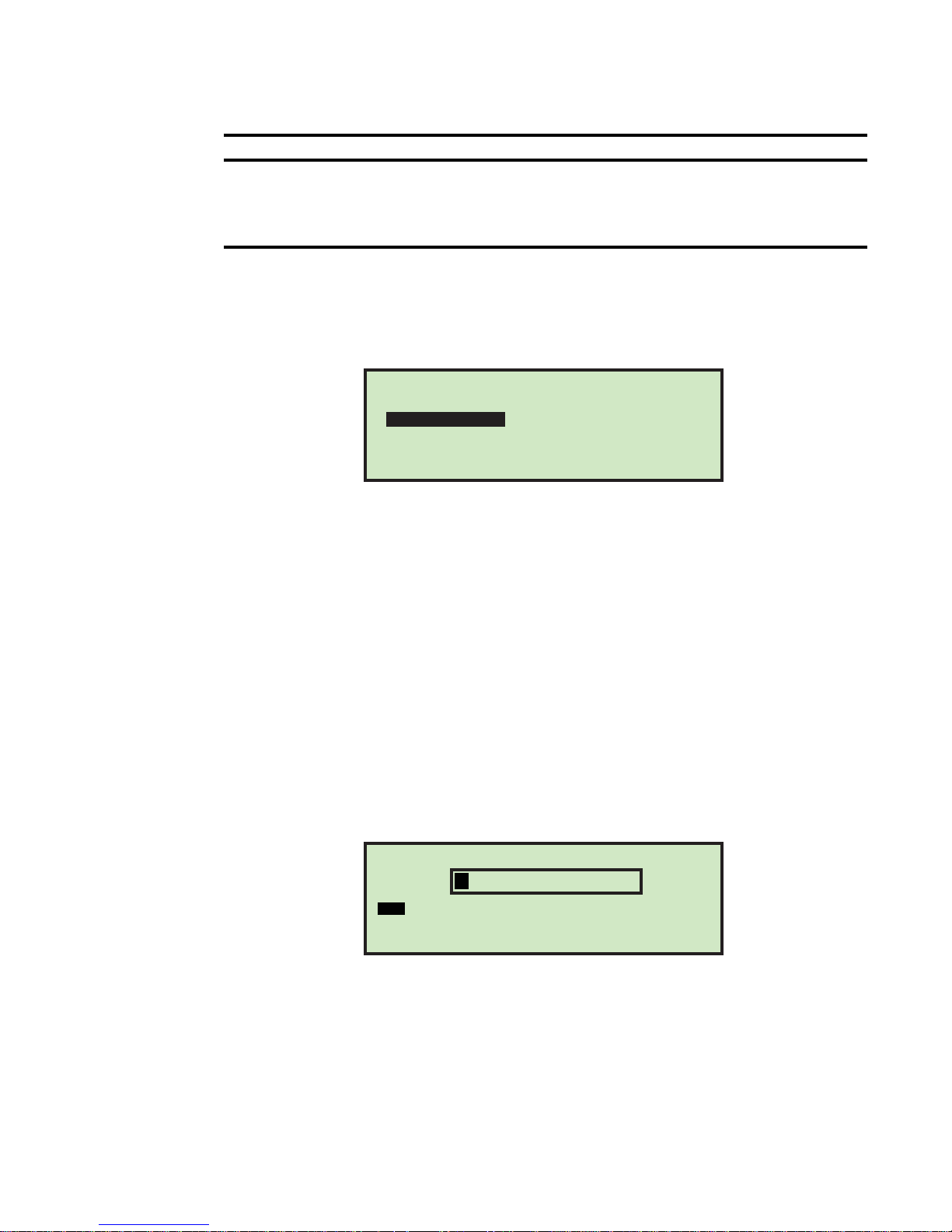
TABLE 3: Model 306 Job Parameters (Continued)
Parameter Description
PRINTER POSITION
Operator Menu
Selecting OPERATOR MENU on the Supervisor screen displays the following options:
Job Parameters
Parameter is used to instruct operator where they should place the ink jet
printer when running this job.
• Choices are from
• This parameter is displayed when PRINTER JOB = YES.
0 to 8, default is 0. Closest to cut edge is 0.
OPERATOR MENU
ADD
MODIFY
PRINT
FIGURE 54: Operator Menu screen
DELETE
SORT LIST
PRINT ALL
• ADD – enter a new operator and setup the operator options.
• DELETE - select an operator from the operator list and delete the operator.
• MODIFY – select an existing operator from the operator list and modify the
operator’s options.
• SORT LIST – alphabetically sort the operator list.
• PRINT – select an operator from the operator list and print all parameters
associated with the selected operator.
• PRINT ALL - print the entire list of operators.
Add Operator
1 On the OPERATOR MENU screen (Figure 54), select ADD. The RENAME OPERA T OR screen
will appear.
RENAME OPERATOR
FIGURE 55: Rename Operator screen
2 Enter the operator’s name using the Arrow buttons to navigate through the
onscreen keypad. Selecting SAV will create the new operator. Pushing the Cancel
button on the keypad will end the operator creation process.
Once you have named the operator and selected SAV, the following screen appears.
A B C D E F G H I J K L M
N O P Q R S T U V W X Y Z
0 1 2 3 4 5 6 7 8 9 Aa INS
OVRDEL < SAV
35Model 306 User Manual - OPEX Corporation
Page 38
Job Parameters
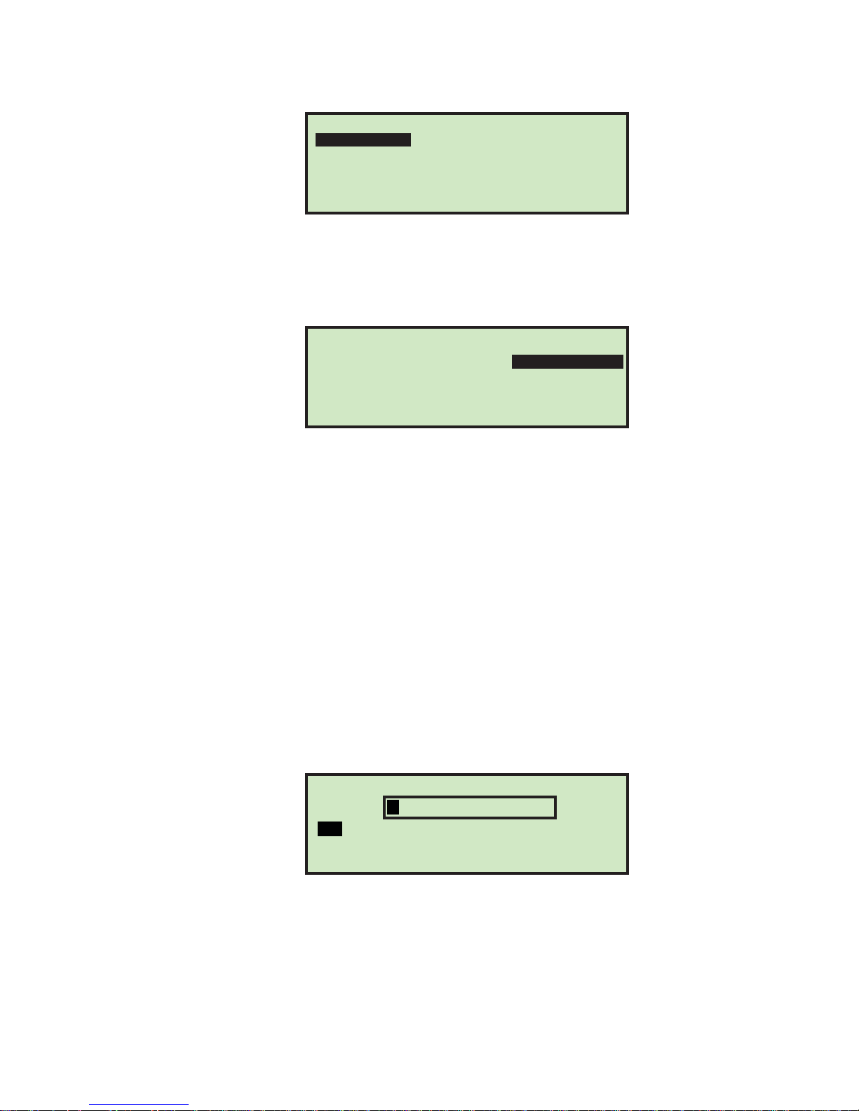
PLACE CURSOR OVER NEW LOCATION
PAT NEW SUPERVISOR
FIGURE 56: Place Cursor Over New Location screen
3 Place the cursor over an existing operator and press Enter to place the operator in
the list. The new operator will be placed after the selected operator, and the MODIFY
OPERATOR screen appears.
MODIFY OPERATOR
OPERATOR NAME
INITIALS
PASSWORD
OPERATOR GROUP
OPERATOR LANGUAGE
FIGURE 57: Modify Operator screen
JANE
J.D.
ABCDE
1
DEFAULT
4 Make any modification to the operator’s parameters using the keypad buttons.
Operator parameters include:
- OPERATOR NAME - change the name of the operator.
- INITIALS - change the initials of the operator. This allows the customer to spray
a shorter audit trail string, if they want to include the operator's name.
- PASSWORD - change the operator’s password.
- OPERATOR GROUP - provides a method to organize operators.
- OPERATOR LANGUAGE - select the language used by the operator.
5 Press Enter to save the changes.
Changing an operator’s initials
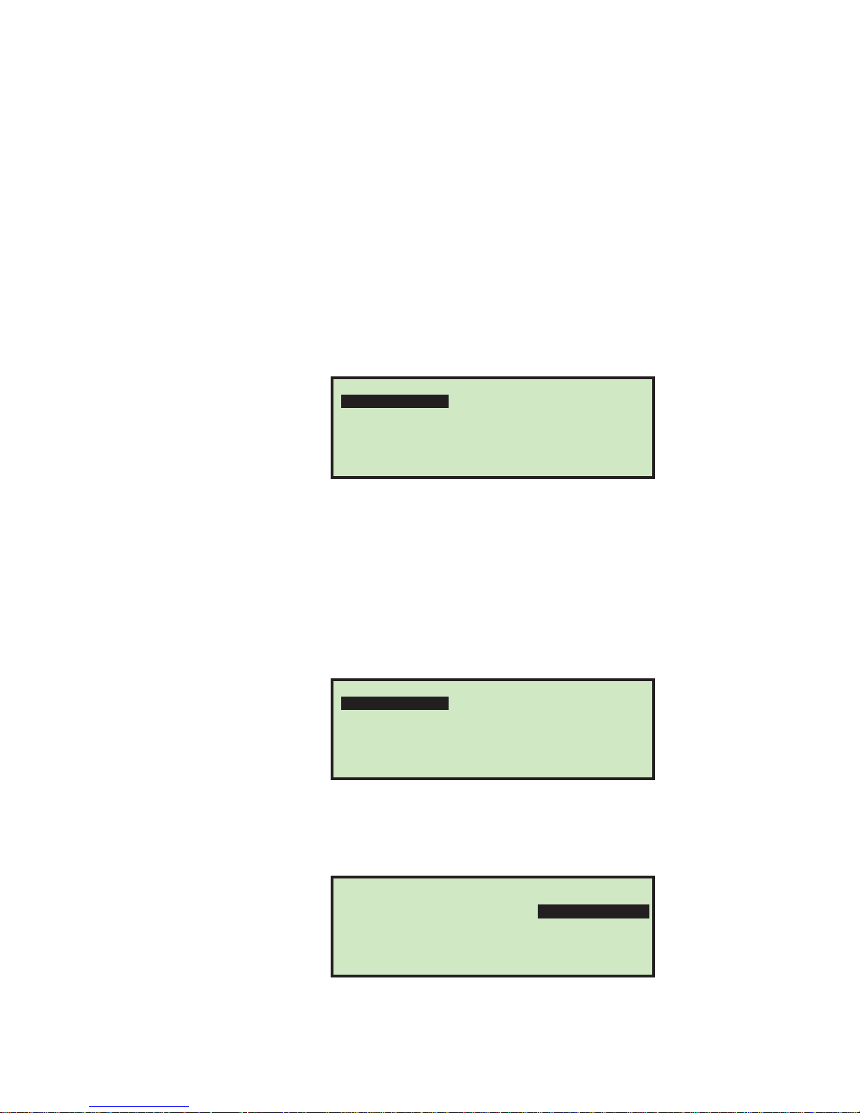
1 On the MODIFY OPERATOR screen, select INITIALS, and press the Enter key. The RENAME
OPER INITIALS screen appears.
FIGURE 58: Rename Operator Initials screen
2 Use the Arrow keys to navigate to OVR and press Enter. This puts you in Over
mode, and the cursor (black box) moves to the first letter.
3 Press Enter.
36 Model 306 User Manual - OPEX Corporation
RENAME OPER INITIALS
J.S.
A B C D E F G H I J K L M
N O P Q R S T U V W X Y Z
0 1 2 3 4 5 6 7 8 9 Aa INS
OVRDEL < SAV
Page 39
Job Parameters
4 Use the Arrow keys to select the first initial of the name. Once selected, press
Enter.
5 Use the Right arrow key to move the cursor to the last initial, and press Enter.
6 Use the Arrow keys to select the last initial of the name. Once selected, press Enter.
7 Press Cancel to exit out of Over mode.
8 Use the Arrow keys to navigate to SAV, and press Enter.
Delete Operator
The supervisor can select an operator from the operator list and delete them.
1 On the OPERAT OR MENU screen (Figure 54), select DELETE. The SELECT OPER TO DELETE
screen appears.
SELECT OPER TO DELETE
DAVE
PAT
JANE
SUPERVISOR
NEW
FIGURE 59: Select Operator to Delete screen
2 Use the Arrow keys to choose an operator, and press Enter to delete the operator.
The operator will be deleted, and the display will return to the OPERATOR MENU
screen.
Modify Operator
1 On the OPERATOR MENU screen (see Figure 54), select MODIFY. The SELECT OPERATOR
screen will appear.
PAT
SUPERVISOR
FIGURE 60: Select Operator screen
2 Use the Arrow keys to choose an operator, and press Enter to select the operator.
The MODIFY OPERATOR screen appears.
SELECT OPERATOR
JANE
MODIFY OPERATOR
NEW
FIGURE 61: Modify Operator screen
OPERATOR NAME
INITIALS
PASSWORD
OPERATOR GROUP
OPERATOR LANGUAGE
JANE
J.D.
ABCDE
1
DEFAULT
37Model 306 User Manual - OPEX Corporation
Page 40
Job Parameters
OPERATOR MENU
DELETE
SORT LIST
PRINT ALL
ADD
MODIFY
PRINT
Selects an individual
operator, and prints all
parameters associated
with them
Prints the entire list
of all operators
3 Make any modification to the operator’s parameters using the Arrow keys.
4 Press Enter to save the changes.
Sort List
1 On the OPERATOR MENU screen (Figure 54), select SORT LIST.
2 Selecting SORT LIST will alphabetically sort the operator list.
Print All or Individual Operator Parameters
NOTE: The optional report printer is required for printing parameters.
Operator information can be printed for an individual or all operators. The printout
includes the name, password, group number and language. The printout choices are
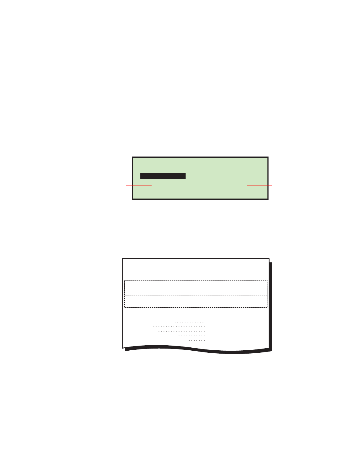
available from the OPERATOR MENU screen.
FIGURE 62: Operator Menu screen
The user must be logged in as supervisor to print out the report.
NOTE: If you want to print information for a specific operator, you will be presented
with an additional screen where you can choose the operator.
OPEX
PARAMETER DESCRIPTION
OPERATOR NAME
INITIALS
PASSWORD
OPERATOR GROUP
OPERATOR LANGUAGE
FIGURE 63: Example printout of Operator information
MODEL 306S
OPERATOR PARAMETERS
PRINTED: JULY 1, 2011 8:38 A.M.
VAL UE
CHRIS
C.B.
1
DEFAULT
38 Model 306 User Manual - OPEX Corporation
Page 41
System Configuration Menu
Allows the Supervisor to view and edit the system configuration parameters.
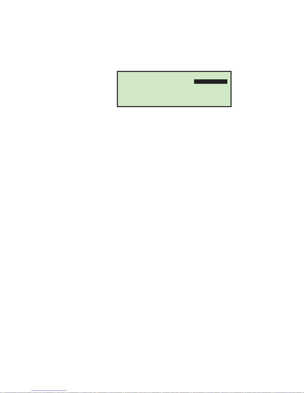
Selecting SYSTEM CONFIGURATION on the Supervisor Main Menu will display the
following screen.
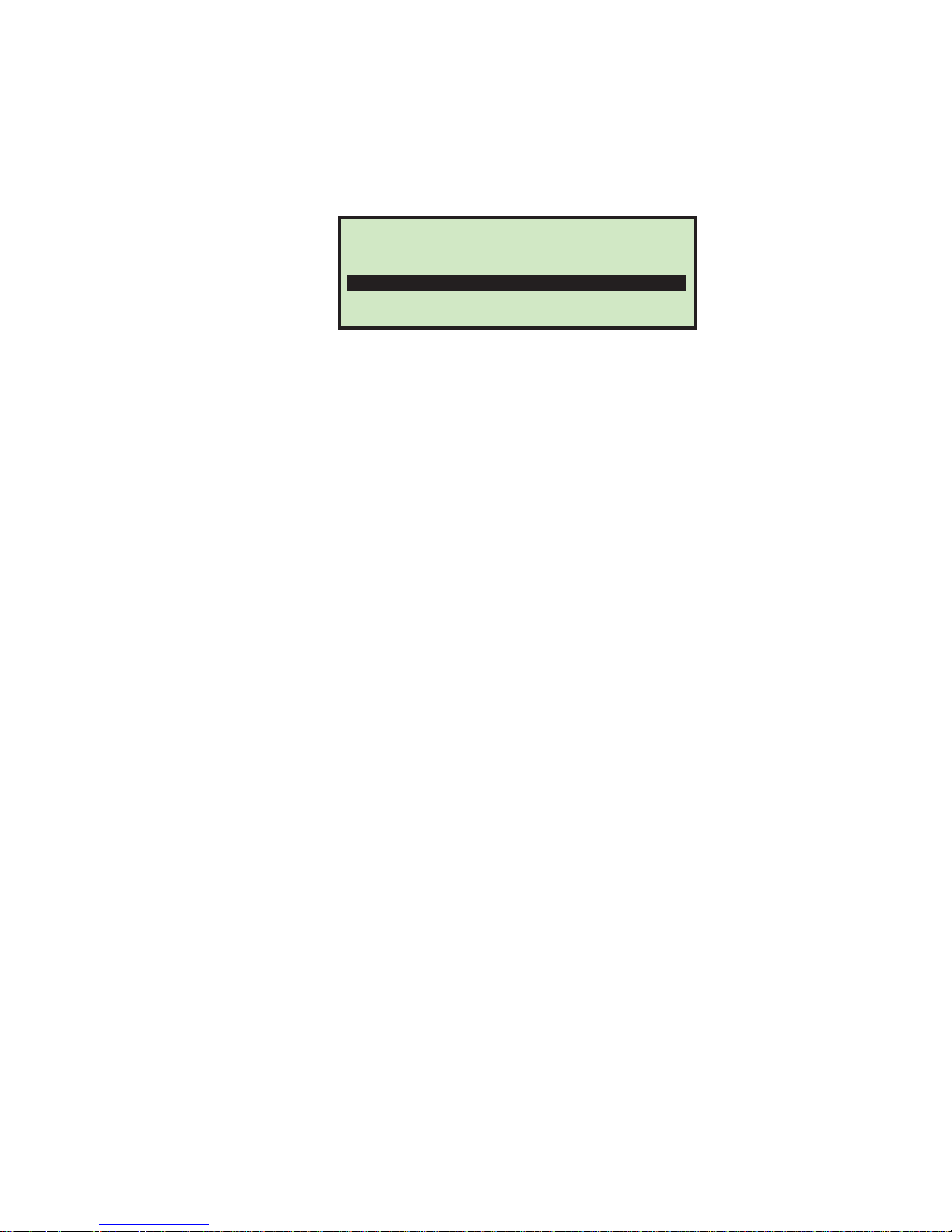
FEED RESTART MODE
BATCHER RESTART MODE
LANGUAGE
DATE FORMAT
FIGURE 64: (Supervisor) System Configuration screen
The System Configuration screen offers the following options:
• FEED RESTART MODE - Default restarting mode of machine when a “feed empty”
condition is detected. Choices are:
- 0 = Auto (default). Auto mode requires the operator to place mail into the feed
area and then it is automatically fed into the machine. Auto mode does not
require the Enter key to be pressed.
- 1 = Manual. Manual mode requires the operator to place mail into the feed area
and then press Enter to restart the machine.
• BATCHER RESTART MODE - Default restarting mode of machine when a “batch full”
condition is detected. Choices are:
- 0 = Auto (default). Auto mode does not require the operator to press the Enter
key to restart the machine.
-
1 = Manual. Manual mode requires the operator to press Enter to restart the
machine.
• LANGUAGE - Default language for the machine. Choices are:
- 0 = English (default)
- 1 = French
- 2 = German
- 3 = French-Canadian
- 4 = Spanish
- 5 = Portuguese
Job Parameters
SYSTEM CONFIGURATION
(AUTO)
(AUTO)
(ENGLISH)
(MMDDYY)
It should be noted that each operator can choose their own language and one of
those selections is “default.” This means that changing this parameter could impact
the language of some operators.
NOTE: The time format displayed by the machine is tied to the language that is
chosen. English will use a 12 hour clock, while all other languages will use
a 24 hour clock.
• DATE FORMAT - Default date/time format for the user interface and reports. Choices
are:
- 0 = MM/DD/YY (default)
- 1 = DD/MM/YY
39Model 306 User Manual - OPEX Corporation
Page 42
Job Parameters
Audit Trail Menu
Selecting AUDIT TRAIL MENU on the Supervisor Main Menu screen displays the AUDIT
TRAIL SETUP screen as shown below.
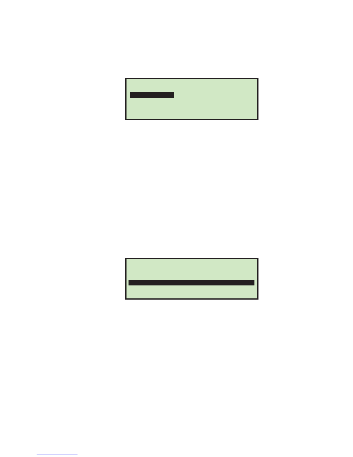
AUDIT TRAIL SETUP
AUDIT TRAIL EDITOR
AUDIT TRAIL ELEMENT SETTINGS
FIGURE 65: Audit Trail Setup screen
The optional audit trail spraying capabilities on the Model 306 are quite extensive.
Managing the audit trails is done at the supervisor level. This menu selection
provides the supervisor with two choices: Audit Trail Editor and Audit Trail Element Settings.
Audit trails define what can be sprayed in each job. A supervisor could use one audit
trail for all of their jobs, share audit trails between a few jobs, or create an audit trail
for each of their jobs. Audit trail elements are provided to help simplify the setup of
audit trails.
Audit Trail Elements
Since both of the menu items have to do with audit trail elements, a summary of the
audit trail elements should be shown before proceeding. Here is a list of the possible
audit trail selections:
• AR - The text representing "Accounts Receivable" will be sprayed. Default in
quotes.
• AT - The text representing "Accounting" will be sprayed. Default in quotes.
• BL - The text representing "Billing" will be sprayed. Default in quotes.
• CN - The text representing "Confidential" will be sprayed. Default in quotes.
• PB - The text for "Process By" will be sprayed. Default in quotes.
• PO - The text for "Processed On" will be sprayed. Default in quotes.
• T1 - User-assigned text will be sprayed. Default is "Text1".
• T2 - User-assigned text will be sprayed. Default is "Text2".
• T3 - User-assigned text will be sprayed. Default is "Text3".
• T4 - User-assigned text will be sprayed. Default is "Text4".
• T5 - User-assigned text will be sprayed. Default is "Text5".
• JN - The name of the job running during audit trail printing will be sprayed.
• DI - The department identification that is entered in the "DEPT. ID" field of the
current job will be sprayed.
• JT - User-assigned text that is entered in the "JOB TEXT" field of the current job
will be sprayed.
• ON - The current operator's name will be sprayed.
• OI - The current operator's initials will be sprayed.
40 Model 306 User Manual - OPEX Corporation
Page 43

Job Parameters
• B1 - When selected, it will spray a Postnet barcode that contains the year, date,
time in seconds and the envelope sequence number. See below for more details.
DT - The month day and year in the format that has been configured in the AUDIT
•
TRAIL PRINTER PARAMETERS screen will be sprayed.
• TI - The hour minute and second in the format that has been configured in the
AUDIT TRAIL PRINTER PARAMETERS screen will be sprayed.
• SN - A five-digit physical count of all envelopes that have been printed on will be
sprayed. It is updated on every envelope sprayed. This value will start at zero and
count up to 65,535 before wrapping to zero.
•
< > - When selected, a character space is entered.
• NL - When selected, a new line is entered. Doing so will cause all following element
selections to be sprayed on the next line.
Barcode 1 (B1) Details
A unique, 11-digit Postnet is sprayed based on the time/day that is set in the RTC
(real-time clock) chip in the machine. The 11 digits in the barcode reflect the
following information:
TABLE 4: Barcode digit information
1 Y - year represented by the least significant digit (limit of wrapping decade)
2-4
5-9 SOD - second of the day, a 5 digit number from 1-86,400 (24 X 60 X 60)
10-1 1
DOY - Day of year, a 3 digit number from 1-366DOY - Day of year, a 3 digit number from 1366
UU - Number representing piece processed within the last second, should range from 1-14 (2
digits needed because 50,000/3,600 = 13.8888)
The above can be described as:
Total digits 11
Position in barcode 1 234 56789 01
Meaning Y DOY SOD UU
Here are some examples:
Barcode value Decodes into:
20320780501
23660003709
Year was 2012 (2), Date was February 1st (032), Time was 2:10:05 am
(07805), 1st piece processed in the second (01)
Year was 2012 (2), Date was December 31st (366), Time was 00:00:37 am
(00037), 9th piece processed in the second (09)
The Model 306 software will optionally provide the supervisor with the ability to
create and maintain a list of audit trails. A maximum of 100 audit trails are
supported. The audit trails are created by selecting elements on lines. The lines can
range from 1 to 4 lines, although the number of lines may be limited by one of the
system configuration parameters.
41Model 306 User Manual - OPEX Corporation
Page 44
Job Parameters
Audit Trail Editor
On the Supervisor>Audit Trail Menu>Audit Trail Setup screen (see Figure 65), select
AUDIT TRAIL EDITOR and press Enter. The CHANGE AUDIT TRAIL LIST screen appears as
shown below.
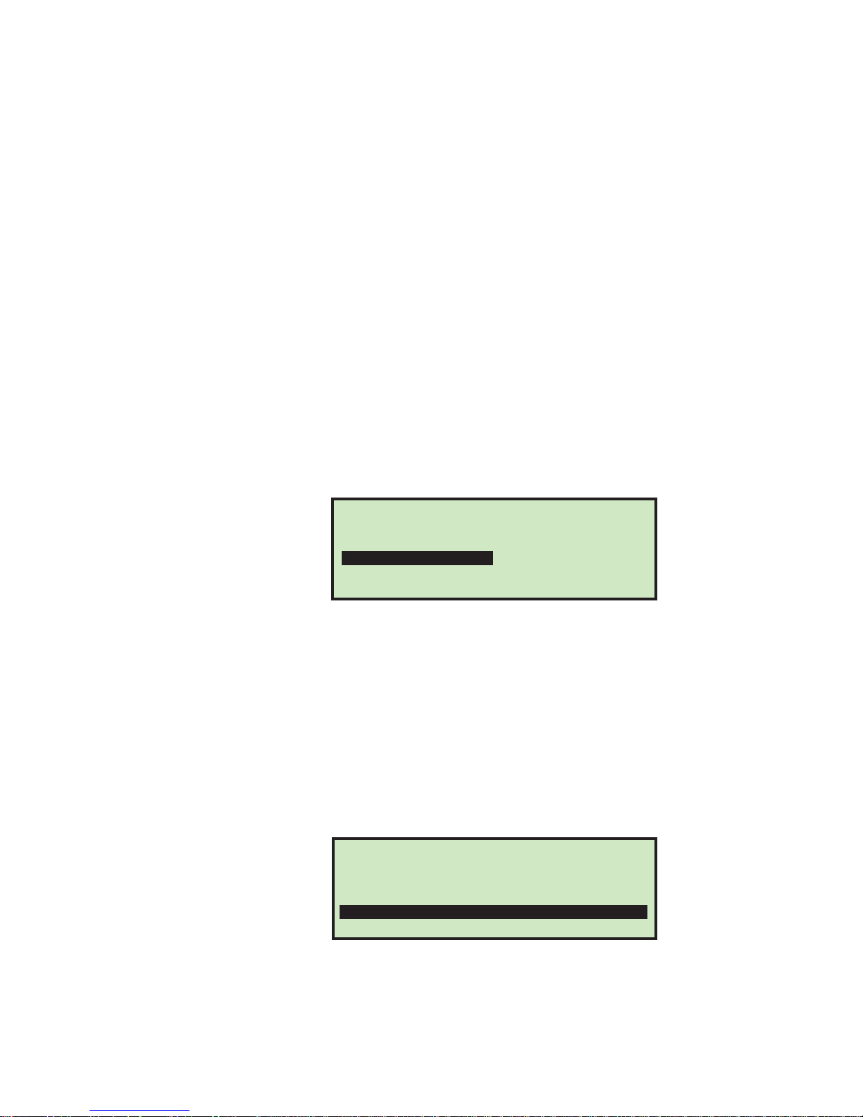
CHANGE AUDIT TRAIL LIST
ADD
MODIFY
SORT LIST
FIGURE 66: Change Audit Trail List screen
This menu will allow the supervisor to perform the following functions:
• ADD - add an audit trail - provides ability to choose location in list
• DELETE - delete an existing audit trail
• MODIFY - modify an existing audit trail
• COPY - an exisiting audit trail can be copied and used as a “template” for a new
audit trail. It must have a new unique audit trail name. Provides ability to choose
location in list.
• SORT LIST - this selection will sort all audit trails alphabetically
DELETE
COPY
Audit Trail Element Settings
On the Supervisor>Audit Trail Menu>Audit Trail Setup screen (see Figure 65), select
AUDIT TRAIL ELEMENT SETTINGS and press Enter. The AUDIT TRAIL ELEMENT SETTINGS screen
appears as shown below.
AUDIT TRAIL ELEMENT SETTINGS
SET/VIEW ELEMENT TEXT
RESET ELEMENT TEXT
FIGURE 67: Audit Trail Element Settings screen
This selection will allow the supervisor to view and optionally modify some of the
audit trail elements. The supervisor also has the option of resetting all element text.
The audit trail element editor/viewer has some nice features such as:
• All elements have a leading and trailing character that shows what type of
element they are.
- Quotes (") indicate that they are associated with their own text.
- Square brackets ([ ]) indicate they contain text that is associated with another
parameter (examples: [job name], [operator name]).
- Elements in brackets (<>) indicate that they will be filled in at run time
(examples: <date>, <sequence number>).
42 Model 306 User Manual - OPEX Corporation
Page 45
• While all of the elements are shown, only the elements in quotes can be modified.
PASSWORD OPTIONS
OPERATOR PASSWORDS SUPERVISOR PASSWORD
The items in quotes appear at the top of the list. The following audit trail elements
can be modified: AR, AT, BL, CN, PB, PO, T1, T2, T3, T4, T5
• When viewing the items, the two-character element shortcut will be shown on the
left (example: AR) and more information about it will be shown on the right
(example: "Accounts Receivable").
• The audit trail editor will provide the following editing tools:
- INS - When selected, the user is allowed to place a newly-selected element
between existing ones in the audit trail.
- OVR - When selected, the user is allowed to place a newly-selected element over
an existing one affectively replacing it.
- DEL - When selected, the entire audit trail is deleted.
- < - When selected, an element is deleted.
- SAV - When selected, the profile is saved.
Password Options
Selecting PASSWORD OPTIONS on the Supervisor Main Menu screen displays the
PASSWORD OPTIONS screen as shown below.
Job Parameters
FIGURE 68: Password Options screen
Operator and Supervisor passwords can be globally enabled or disabled from this
screen. The defaults for the passwords are set to enabled. If passwords are enabled,
the operator or supervisor will only be prompted to enter a password if one already
exists.
To disable operator passwords
1 Select PASSWORD OPTIONS on the Supervisor Main Menu screen.
2 Use the left/right arrows to select OPERATOR PASSWORDS and press Enter. The
Operator Passwords screen appears as shown below.
OPERATOR PASSWORDS
DO NOT ALLOW OPERATOR PASSWORDS
ALLOW OPERATOR PASSWORDS
FIGURE 69: Operator Passwords screen
3 Use the arrows to select DO NOT ALLOW OPERATOR PASSWORDS, and press Enter.
43Model 306 User Manual - OPEX Corporation
Page 46
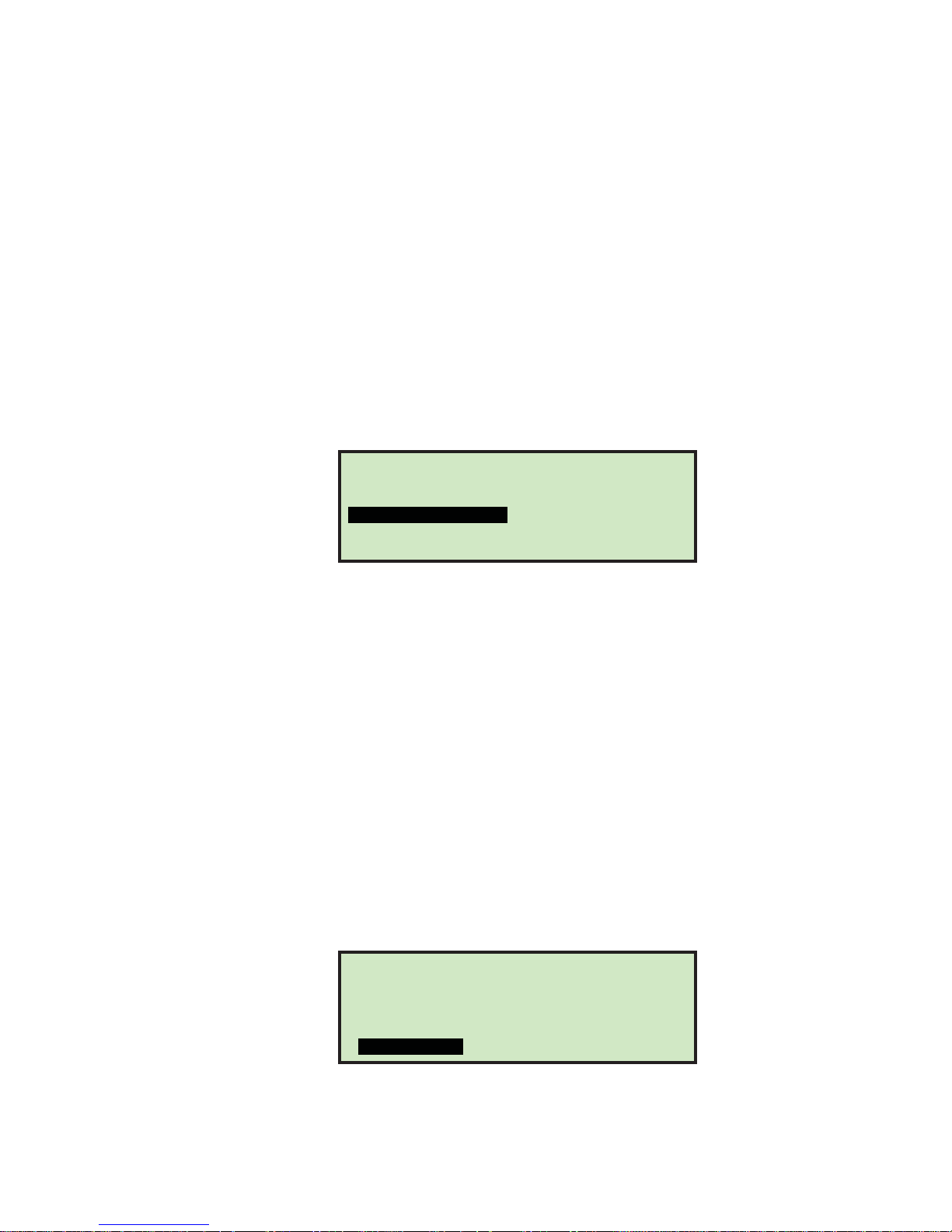
Statistics
Statistics
Operator Statistics
The operator and supervisor have the ability to view statistics.
The operator has the ability to display and optionally print their statistics on the
optional stats reports printer. The operator can only view runs that were saved in
their name.
More details of statistics can be found in “Supervisor Statistics” on page-45.
To view and/or print statistics
1 On the Run screen, use the Up/Down arrow buttons to select and highlight
STATISTICS, then press Enter. The DISPLA Y STATISTICS screen appears as shown below.
DISPLAY STATISTICS
Time Range: All times
VIEW DETAILS
PRINT DETAILS
PAPER FEED
FIGURE 70: Display Statistics screen
VIEW SUMMARY
PRINT SUMMARY
SET TIME RANGE
The choices are:
- VIEW DETAILS - Pulls together all jobs run by this operator in the specified time
range each in an individual view (in other words, if the operator ran 4 jobs, the
data will be pulled together into 4 views).
- VIEW SUMMARY - Pulls together all jobs run by this operator in the specified time
range in one view.
- PRINT DETAILS - provides a printout of the details described above. Requires the
optional stats report printer.
- PRINT SUMMARY - provides a printout of the summary described above.
- PAPER FEED - allows you to advance paper in the reports printer (by pressing
Enter), or exit out of paper feed mode (by pressing Cancel).
- SET TIME RANGE - allows operator to set specified date and time for pulling the
above information together. More details in supervisor section.
2 On the DISPLAY STATISTICS screen, use the arrow buttons to select and highlight SET
TIME RANGE, and press Enter. The SELECT TIME RANGE screen appears (see Figure 71).
FIGURE 71: Select Time Range screen
44 Model 306 User Manual - OPEX Corporation
SELECT TIME RANGE
PAST 8 HRS
TODAY
YESTERDAY
ALL TIMES
PAST 16 HRS
THIS WEEK
LAST WEEK
PAST 24 HRS
THIS MONTH
LAST MONTH
Page 47
Statistics
3 On the SELECT TIME RANGE screen, use the arrow buttons to select and highlight the
desired time range, and press Enter.
4 Using the navigation buttons, select and highlight the desired view or print
function and press Enter.
DISPLAY STATISTICS
Time Range: All times
FIGURE 72: Display Statistics screen
Based on the selection made, the information is either displayed or printed. The
following graphic shows an example of the VIEW DETAILS selection.
FIGURE 73: Statistics detail example
Supervisor Statistics
The Supervisor has the ability to view all operator statistics.
1 Log in as supervisor. The Supervisor Main Menu appears as shown below.
VIEW DETAILS
PRINT DETAILS
PAPER FEED
OPERATOR: CHRIS JOB: AMEX001
FROM: June 28, 2011 8:30 A.M.
TO: July 14, 2011 4:30 P.M.
COUNT: 00068 TIME: 00:02 RATE: 2006/HR
EXCEPTIONS: 00000
SIDE COUNT: 00000 BATCHES: 000
LOWER COUNT: 00000 BATCHES: 000
VIEW SUMMARY
PRINT SUMMARY
SET TIME RANGE
Monday, July 20, 2011 9:11 A.M.
SUPERVISOR
JOB MENU
OPERATOR MENU
AUDIT TRAIL MENU
FIGURE 74: Supervisor Main Menu screen
2 Use the arrow buttons to highlight STATISTICS MENU, and press Enter. The Statistics
menu appears as shown below.
STATISTICS MENU
SYSTEM CONFIGURATION
PASSWORD OPTIONS
STATISTICS
DISPLAY DATA
RESET DATA
FIGURE 75: Supervisor level - Statistics menu
PRINT DATA
RESET CLOCK
45Model 306 User Manual - OPEX Corporation
Page 48
Statistics
The Supervisor Statistics menu offers the supervisor the ability to view and edit
additional information.
Display Data
This screen allows you to view statistical data for all or specific operators.
1 In the Supervisor level - Statistics Menu (Figure 75), select DISPLAY DATA and press
Enter.
The DISPLAY STATISTICS screen appears as shown below.
DISPLAY STATISTICS
Time Range: All times
DETAILS REPORT
JOB REPORT
INDIVIDUAL RUN
FIGURE 76: Supervisor level - Display Statistics menu
SUMMARY REPORT
OPERATOR REPORT
SET TIME RANGE
Display Statistics offers the following:
- DETAILS REPORT - displays statistics sorted by both job and operator.
- SUMMARY REPORT - displays statistics for all jobs.
- JOB REPORT - displays statistics for each job.
- OPERATOR REPORT - displays statistics for each operator.
- INDIVIDUAL RUN - displays individual statistics for each job run.
- SET TIME RANGE - You can also specify the time range of the statistics you
want to view
Use the left/right arrow buttons to view each available report.
Print Data
In the Supervisor level - Statistics Menu (Figure 75), selecting PRINT DATA opens the
PRINT STATISTICS window where you can choose from the following options:
- DETAILS REPORT - prints a Detailed Statistics Report.
- SUMMARY REPORT - prints a Summary Statistics Report.
- JOB REPORT - prints a Job Statistics Report.
- OPERATOR REPORT - prints an Operator Statistics Report.
- PAPER FEED - advances paper through the printer.
- SET TIME RANGE - select a time range for your printed report.
46 Model 306 User Manual - OPEX Corporation
Page 49
Statistics
Reset Data
In the Supervisor level - Statistics Menu (Figure 75), selecting RESET DATA will clear all
statistics. When this is selected, you are first presented with a warning screen.
WARNING ALL STAT
DATA WILL BE LOST
PUSH UP KEY TO ERASE DATA
PUSH ANY OTHER KEY TO QUIT
FIGURE 77: Reset Data warning screen
1 Press the Up key to erase and reset all statistical data, or press any other key to
exit from this screen.
Set Clock
1 In the Supervisor level - Statistics Menu (Figure 75), selecting PRINT DATA opens
the PRINT STATISTICS window where you can set the day, date and time of the
system.
SET CLOCK
Monday, June 27, 2011 9:44 A.M.
DAY MONTH DATE YEAR HOUR MINUTE AM/PM
FIGURE 78: Set Clock screen
2 Use the left/right arrow buttons to select one of the clock’s settings (example:
Day, Month, Date, Year, etc.).
3 Use the up/down arrow buttons to set the clock.
4 When you are finished updating the clock, press Enter.
47Model 306 User Manual - OPEX Corporation
Page 50

Troubleshooting
Troubleshooting
When a machine stops for a reason other than the operator canceling out of a job,
the LCD will display an error message, as described below:
TABLE 5: Model 306 Error messages
Error Message Description
PLEASE CHECK MAIL
FEEDER
PLEASE CHECK FEED
EXIT
THICKNESS DETECT
OVER RANGE
THICKNESS DETECT
UNDER RANGE
PIECE TOO SHORT OR
MISSED TMD
REMOVE PIECE HEIGHT
SENSOR AREA
PLEASE CLEAR THE
CUTTER AREA
Once the Feed Empty sensor goes blocked, software starts a timer for
FEED EMPTY TIMEOUT (machine parameter) period of time. If this
timer times out and no mail was placed in the feed area, then this
message is displayed. At the same time another timer is started for
FEED NO ACTIVITY TIMEOUT (machine parameter) in seconds.
While waiting for this timer to time out, the software will continue to
look at the Feed Empty sensor to show mail was placed into the
feeder. If this second timer times out, then the machine will turn off
and the message is removed from the screen.
If the feeder clutch is engaged, the system is running in continuous
mode and the Feed Exit sensor is detected to be blocked longer than
the MAX SENSOR BLOCKED TIME (machine parameter) then this
jam will be called.
This jam is called during machine startup, when all sensors are
checked to be clear before the motor is turned on. If the Feed Exit
sensor is found to be blocked, then the motors are not started and
instead this jam is called.
Before motors are turned on to run mail, the thickness detect module
is checked for proper operation. If the TMD reading if above TMD
MAXIMUM NULL READING (machine parameter), then this jam will
be called.
Before motors are turned on to run mail, the thickness detect module
is checked for proper operation. If the TMD reading is below TMD
MINIMUM NULL READING (machine parameter), then this jam will
be called.
After the thickness data is captured using the TMD, software will run
some filtering algorithms on the collected data. If there is no data left
after filtering, then this jam will be called.
This jam is called during machine startup, when all sensors are
checked to be clear before the motor is turned on. If the Env Height
sensor is found to be blocked, then the motors are not started and
instead this jam is called. Additionally, this jam is called when the
machine is running and the height sensor is blocked when the Feed
Exit and Cutter Path sensors are unblocked for MAX SENSOR
BLOCKED TIME (machine parameter).
This jam is called during machine startup, when all sensors are
checked to be clear before the motor is turned on. If the Cutter Path
sensor is found to be blocked, then the motors are not started and
instead this jam is called.
This jam is called if the Cutter Path sensor is detected to be blocked
longer than the MAX SENSOR BLOCKED TIME (machine parameter)
when the machine is processing mail.
48 Model 306 User Manual - OPEX Corporation
Page 51

TABLE 5: Model 306 Error messages (Continued)
Error Message Description
This jam is called during machine startup, when all sensors are
checked to be clear before the motor is turned on. If the COUNTER
PLEASE CLEAR THE
COUNTER AREA
PLEASE CLEAR LENGTH
SENSOR AREA
UNEXPECTED ENVELOPE
AT COUNTER
PLEASE CLEAR THE SIDE
BIN PATH
AUDIT TRAIL PRINTER
NOT DETECTED
AUDIT TRAIL PRINTER
CARTRIDGE DOOR OPEN
AUDIT TRAIL PRINTER
CARTRIDGE FAULT
AUDIT TRAIL PRINTER
COMM FAULT
AUDIT TRAIL PRINTER
FAULT DETECTED
COULD NOT MAKE SORT
DECISION
PATH is found to be blocked, then the motors are not started and
instead this jam is called.
This jam is called if the COUNTER PATH is detected to be blocked
longer than MAX SENSOR BLOCKED TIME (machine parameter)
when the machine is processing mail.
This jam is called during machine startup, when all sensors are
checked to be clear before the motor is turned on. If the Length Path
sensor is found to be blocked, then the motors are not started and
instead this jam is called.
This jam is also called if the Length Path sensor is detected to be
blocked longer than the MAX SENSOR BLOCKED TIME (machine
parameter) when the machine is processing mail.
This jam is called if a lead edge is detected at the COUNTER PATH,
yet that lead edge was not seen at the Cutter Path sensor. This jam
will only be called when the currently running job is performing any
sorting activity (length, height and/or thickness).
This jam is called during machine startup, when all sensors are
checked to be clear before the motor is turned on. This jam is called if
the Side Bin Path sensor is detected to be blocked longer than the
MAX SENSOR BLOCKED TIME (machine parameter).
Prior to starting motors, the software will send a message over to the
printer. If the printer does not communicate back, then this jam will be
called.
Prior to starting motors, the software will check to see if the cartridge
door is open. If the interlock indicates the printer cartridge door is
open, then this jam will be called.
Prior to starting motors, the software will check to see if the cartridge
is present. If the IMTECH software indicates there is an issue with the
cartridge, then this jam will be called.
Prior to starting motors, the software will send a message over to the
printer. If the printer response indicates a problem, then this jam will
be called. During printing jobs, the printer also responds to print
messages with status. If a problem is detected at this time, then this
jam will be called.
Prior to starting motors, the software will send a message over to the
printer. If the printer attempts to communicate back and there is some
form of communication issue, then this jam will be called.
Called if piece arrives at the COUNTER PATH and there isn't enough
information collected to make a sort decision.
This jam is only called when a sort job or a print job is being run.
The calling of this jam will be depend on the setting of the
EXCEPTION THRESHOLD job parameter and the number of
exceptions.
Troubleshooting
49Model 306 User Manual - OPEX Corporation
Page 52

Routine Maintenance
!
Routine Maintenance
It is important that you keep your machine clean and in good working order. This
will prolong the overall life of the machine and result in longer periods of “up” time.
Failure to perform daily cleaning tasks may result in the voiding of your service
contract. Therefore, it is vitally important that you perform the following tasks at
least once per day:
Clean the Model 306
1 Use a vacuum cleaner with a crevice tool to vacuum dust and debris from all
exposed components of the machine.
2 Clean the exterior surfaces and panels with a multi-purpose type cleaner.
- Use denatured alcohol on areas with stains, if necessary.
- Any non-flammable commercially available cleaning solution may be used to
clean the machine. When cleaning the OPEX Model 306, DO NOT USE aerosol
cleaners or compressed air because of the flammable nature of many of these
products. There is a risk of equipment malfunction and/or injury associated
with the use of aerosol cleaners on OPEX equipment prior to the operation of
equipment.
- When cleaning glass and plastic surfaces, use detergent-based cleaners such
as Fantastic™ or Formula 409™. Detergent-based cleaners are recommended,
because they do not cause component degradation.
A cloth soaked with cleaning detergent or similar material should never be used
DANGER:
- Wipe dust and debris from the sensors. Debris build-up can cause jams. Accumulations of dirt and debris can cover sensors, preventing them from working
effectively. This will hinder machine performance.
3 Before carefully removing any chips or paper jammed in the cutter, unplug the
machine.
to clean an object such as a belt or roller when the belt or roller is being driven
by the system. Use of a cloth or similar material on moving mechanisms can
result in personal injury. If a belt, pulley or similar part needs to be cleaned, it
should be cleaned while stationary.
4 Empty the cutter trash bin. The mill cutter chips are collected in a trash bin
located in front of the operator’s feet. The bin should be checked and emptied on a
regular basis. Failure to empty the trash bin will result in chips “haystacking” up
toward the cutter mechanism, preventing additional chips from falling into the
trash. This may lead to the cutter itself being jammed.
If this happens, empty the trash bin. Then clear the cutter so that no chips
remain, using a pencil or similar tool to push down chips which have collected
between the cutter and surrounding frame.
50 Model 306 User Manual - OPEX Corporation
Page 53
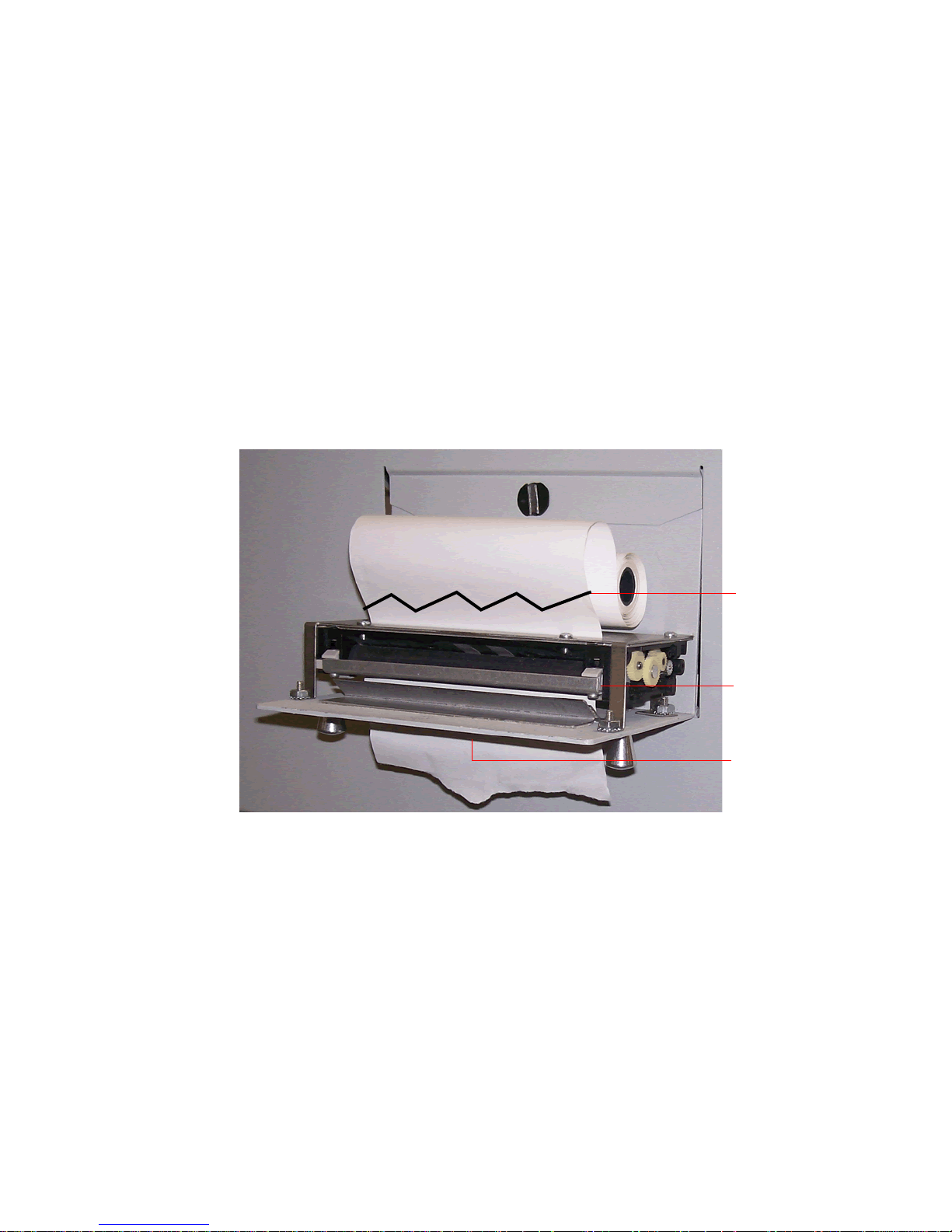
Replacing Report Printer Paper
Release lever
Feed slot
Tear paper here
The printer will automatically detect if it’s out of paper. A “No paper in printer”
message will be displayed. The steps below describe how to replace printer paper in
the Model 306. The printer is accessed from the side of the machine.
1 Open the printer door. The printer drawer is hinged on the bottom. The drawer
will open and swing down on its hinge.
2 Check to see if the entire old roll of paper has fed through the printhead.
- If all of the paper is out of the printhead, go to step 4.
- If there is any paper remaining in the printhead, go to step 3.
3 Remove the remaining paper:
a. Do not attempt to pull the paper out of the printhead or try to feed the paper
through the printer rollers manually.
b. Tear or cut the paper as shown below and lift the old roll out of the printer.
Routine Maintenance
FIGURE 79: Paper removal
c. Press the release lever down and pull the remaining paper out of the printer.
d. Once the paper has been removed from the printer, lift the release lever up
until it clicks in place.
4 Place a new roll of paper on the metal shaft and install the roll in the printer so
that the paper will feed from the top of the roll (see Figure 79). The paper will
automatically feed into the printer.
5 If you want to advance the paper further, access the SUPERVISOR > STATISTICS MENU >
PRINT DATA > PAPER FEED screen, and press and hold Enter until the report printer
has fed several inches of paper through the printhead.
6 Release the Enter button and close the printer door.
51Model 306 User Manual - OPEX Corporation
Page 54
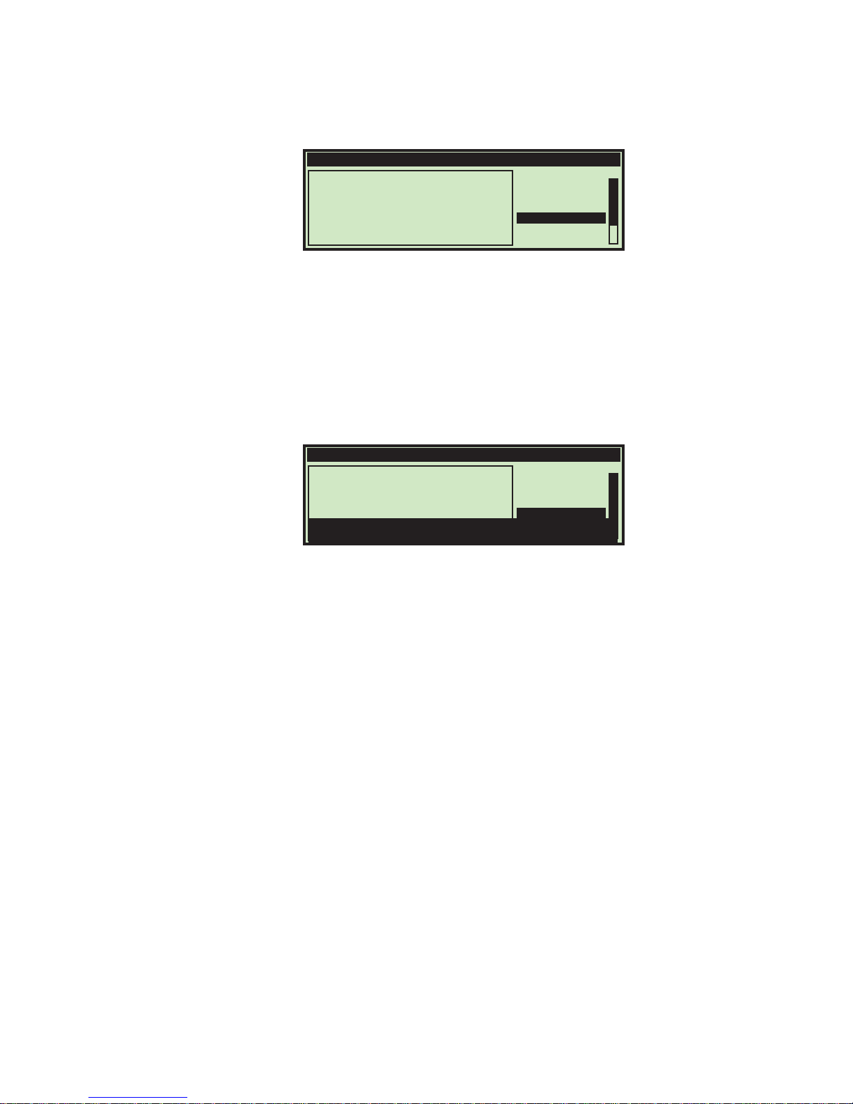
Routine Maintenance
Cleaning the Audit trail printer cartridge head
FIGURE 80: Run screen with PRINT = ON
In jobs that have printing enabled (as in Figure 80), the PRINT selection will provide
the operator with the ability to clean the print cartridge head. This is accomplished
by allowing the user to spit ink out of the cartridge, which will help to get the ink
flowing.
1 On the Run screen, use the Arrow buttons to select PRINT, and press Enter.
2 Press the Enter key a few times until “PRINT: SPIT” appears with instructions, as in
Figure 81.
OPERATOR:JOANNA JOB:TEST
00032
(S) SIDE 00000
(P) LOWER 00000
OPERATOR:JOANNA JOB:TEST
(E)00000
RUN
CHANGE JOB
CHANGE OPER
PRINT: SPIT
ZERO COUNT
STATISTICS
RUN
00032
(S) SIDE 00000
(P) LOWER 00000
Press the DOWN key to spit or the
ENTER key to advance.
FIGURE 81: Run screen with PRINT = SPIT
(E)00000
CHANGE JOB
CHANGE OPER
PRINT: SPIT
ZERO COUNT
STATISTICS
3 Insert a scrap piece of paper underneath the printer, and press the Down arrow
key. You may have to do this a few times if the printer is clogged.
4 When you are pleased with the results, press the Cancel button.
52 Model 306 User Manual - OPEX Corporation
Page 55

Specifications
Machine Dimensions
Power
BTU
Specifications
Length: 47.75” (121.285 cm)
Depth: 21” (53.34 cm)
Height: 58” (147.32 cm)
Weight: 245 lbs
115 VAC, 60Hz, 8.5 Amps (US)
230 VAC, 50Hz, 5.5 Amps (Euro)
3338 BTU/hour (115 VAC)
4317 BTU/hour (230 VAC)
Speed
Envelope Sizes
Thickness
Depth of Cut
Feeder Hopper Capacity
Stand & Waste bin
306 Options
306s Options
Power Source
Power Disconnect
Up to 40,000/hour
Lengths up to 13.5" (34.29 cm)
Up to 0.50” (1.27 cm)
Nine settings, from 0.01” (0.03 cm) from envelope edge up to 0.125”
(0.32 cm) in depth (settings 1-8), also no cut (setting 0)
Up to 400 envelopes
Included
Batch Counter (counts down to preset size and stops or pauses),
Hi-Speed Inkjet printer (Prints a variety of custom strings, date & time,
sequential numbering & ID Tag barcodes),
Stats Report Printer (Produces a variety of statistics reports for
monitoring machine performan c e )
Sorter (thickness, height, length) with Output Bin,
Sorter (thickness, height, length) with 90 Degree Powered Conveyor
The socket outlet must be installed near the equipment and must be
easily accessible at all times.
The electrical disconnect for this machine is the AC power cord at the
back of the machine. Unplug the cord to remove all electrical power.
53Model 306 User Manual - OPEX Corporation
Page 56

Specifications
54 Model 306 User Manual - OPEX Corporation
 Loading...