

Page 1

Electromagnetic Lock Installation Instruction
(Indoor Series)
In-swinging
Frameless
Glass Door
Out-swinging
Specifications
Holding Force Curve & Accessories
Optional Bracket
Regular Installation
With L-bracket for
narrow door frames
With U-bracket for frameless
glass door leaf
With LZ-bracket for
in-swinging door frames
All RightsReserved.
PublishPMUAMEM Ver.E :2007.01.24
4-1
Model
13700
500mA@12VDC
250mA@24VDC
L-300, EM-10001L bracket for narrow
door frames.
LZ-300, LZ-300N, EM-10001LZ bracket for
in-swinging doors.
600 lbs(272 Kg)
Please note that the actual accessory pack varies according to the
electromagnetic lock model.
Electromagnet
Mounting Plate
Armature
Plate
Sexnut Bolt
Guide Pins
Rubber Washer
Washer
Fixing screw
Brass Sleeves
Anti-tamper Cap
Armature screw
Door spacer
" L Z " Bracket
UBK Bracket
" L " Bracket
Out-swinging
Out-swinging
Identify the door swinging direction and inspect the door frame header to determine if bracket is required. AL- bracket, LZ-bracket or U-bracket(optional)
may be required for the electromagnet depending on the frame header and swinging direction.
Narrow frame
Holding force
Voltage (12 VDC)
Current Drew
Optional Bracket
Holding Force
The holding force of the electromagnetic lock depends on the voltage of
the power supply. The graph below illustrates the change of the holding
force under different voltage. The holding forces of the electromagnetic
lock were tested by "Colinear" force.
Page 2
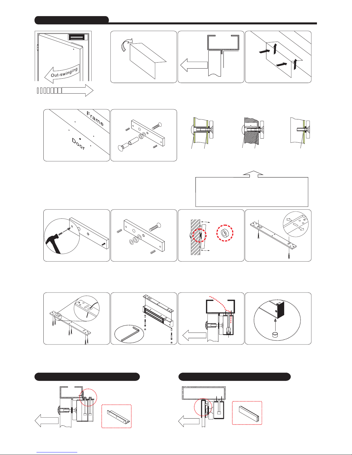
" L " Bracket
(Option)
Out-swinging
7
Put one rubber washer between
two washers, and place them over
the armature screw between the
armature plate and the door.
9
Screw the two self-tapping screws
in the slotted holes of the mounting
plate and adjust the position of the
mounting plate so that it and the
armature plate from a 90-degree
angle.
Template
1
Fold the mounting template along
the dotted line to a 90-degree
angle.
door
Out-swinging
Template
2
Close the door, find a mounting
location on the door frame near the
upper free-moving corner of the door,
as close to the corner of the door
frame as possible.
3
Place the template against the door
and frame. Drill two holes in the frame
and three holes in door as indicated
on the template.
8
This will allow the armature plate to
pivot slightly around the armature
screw in order to compensate for
door misalignment.
Rubber Washer
Regular Installation
4
Drill two holes in the frame and
three holes in the door as
indicated on the template.
6.8mm for M8-1.25 thread
16mm 8mm 12.7mm 8mm
Drill an8 mm holethrough
door, from sexnut bolt side
only, enlarge the8mm hole
to 16mm.
Micro EM-locks(300 LBS) maximumthickness of dooris 44 mm.
Mini EM-locks(600 LBS) maximumthickness of dooris 50 mm.
Midi EM-locks(800 LBS) maximumthickness of dooris 48 mm.
Standard EM-locks(1200 LBS) maximumthickness of dooris 46 mm.
Recommendation:
Drill an8 mm holethru
door fromsexnut bolt
side ofdoor, drill 12.7mm
hole, 36mmin depth.
Drill an6.8 mm dia.
Hole andtap for
M8x12.5 thread.
Hollow Metal Door
Solid Door Reinforced Door
36mm
5
Mounting the armature plate to
the door . Actual installation
varies according to door style.
Armature Plate
10
Once the position is correct, use
the screws to permanently mount
the mounting plate, And drill the
cable access hole.
Cable
12
Connect the power lead, and test
the unit.
Holding Force
Power
11
Use the Allen wrench to screw the
Fixing screws and Brass Sleeves
through the bottom of the
electromagnet into the mounting
plate.
Allen wrench
Finish
Insert the anti-tamper caps into the
mounting screw access holes. This
should be the last step, as once the
tamper caps are in place, they will
be difficult to remove.
With L bracket for narrow door frames
With U bracket for frameless glass doors
Universal glass door kits are
compatible with lock models,
except 1200 lbs serial.
Out-swinging
(Option)
UBK Bracket
UBK-008 for 8mm of glass door
UBK-010 for 10mm of glass door
UBK-012 for 12mm of glass door
UBK-014 for 14mm of glass door
4-2
6
Make sure the Guide Pins are in
the two guide pin holes.
Guide Pins
Installation Steps
All RightsReserved.
PublishPMUAMEM Ver.E :2007.01.24
L bracket is used as an extension
on narrow door frames to provide
adequate mounting surface.
Page 3
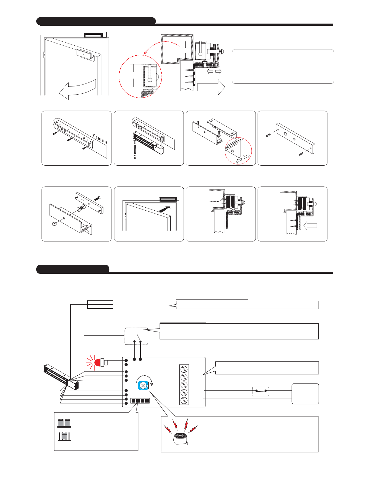
Installation Steps of LZ bracket for In-swinging doors
I
n
-
s
w
i
n
g
i
n
g
The "X" value is 48mm which is the
minimum requirement width of the
door frame for Model No.13700
600 lbs electromagnet locks.
X
In-swinging
X
21
6
Power
7 Finish
4
5
3
With LZ bracket for In-swinging doors
Connecting Diagram
+
+
-
-
N.O.
COM.
N.C.
Power
Input
Power
supply
Trigger
SPDT relay
3A@12VDC
Status LED:
GREEN: Unlocked
RED :Locked
Off: No power
Coil
Sensor input
Timer Adjust
Shorten
4-3
12Vdc
24Vdc
Voltage Selection jumpers
Check jumpersettings before
connecting thelock to 24VDC
input power. Damage to the
lock mayresult from incorrect
jumper settings.
The modelswith "magnet bondsensor
output"
Magnet bond
sensor output
Control DeviceN.C. contact or
Access Relay
Door HeldOpen Alarm
"Door Held Open Alarm
If the"Door Held OpenAlarm timer is set for 5 seconds, the following
will happen: If the door is opened , but remains open for more than 5
seconds, then an audible alarm will sound until the door is closed
correctly.
"
"
The time for the depends on the "VR timer
adjust" within90 seconds.
The electromagnetic lock will automatic unlock internally after the
triggers connect to each other. The time for the door to relock back
dependson the"VRtimer adjust" within 90 seconds.
Reedswitch rated0.25A@30VDC
Relocking timer
Door PositionSensor
Door SensorN.O.
Door SensorCom.
Door SensorN.C.
Orange:
White:
Brown:
All RightsReserved.
PublishPMUAMEM Ver.E :2007.01.24
For Lock status
monitoring models
For Door status monitoring models
For Time delay models
For Bond sensor monitoring models
For Options
Close the door. Measure the correct
position by bringing the armature
plate close to the contact surface of
the electromagnetic lock.
Turn on the power of EM-Lock,
and let the armature plate bond
to the EM-lock. Adjust the position
between the Z bracket and the
door frame.
Once the position is correct,
use the screws to permanently
mount the Z part of LZ bracket
on the door. This should be the
last step.
Put one rubber washer between
armature plate and the Z part of
LZ bracket, and place them over
the 8mm armature screw.
Fasten the electromagnetic lock
on the L bracket by using the
fixing screw.
Find a mounting location on the
door frame for the L bracket. Make
sure that the door is still closable.
Insert the guide pins into the
armature plate. The guide pins
will prevent the armature plate to
pivot around.
Assemble the Z bracket, and make
sure that the Z bracket is adjustable.
Page 4
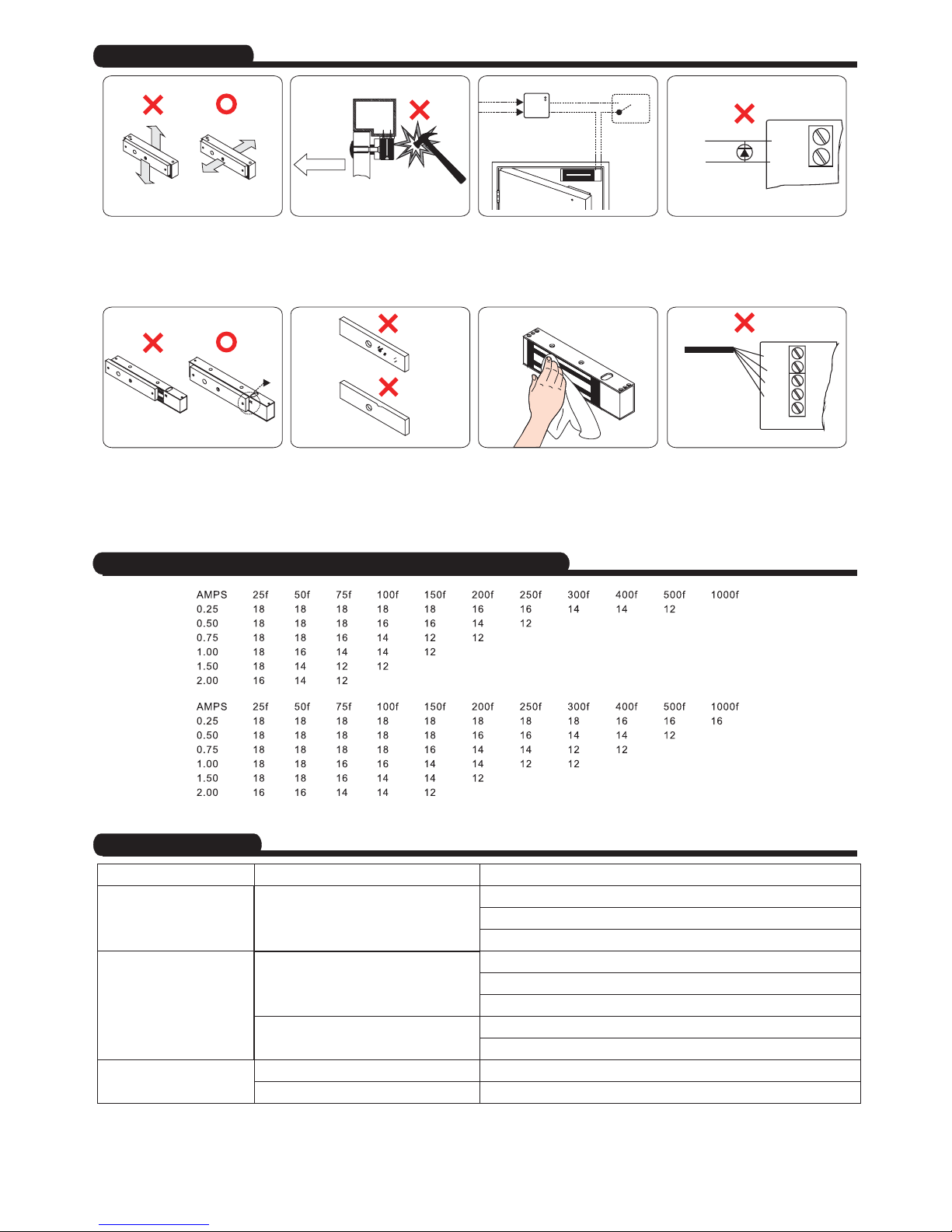
Problem Possible Cause Solution
Door doesnot lock
No power
Poor contactbetween electromagnet and
armature plate
Low voltageor incorrect voltagesetting
A secondary diode was installed across
the electromagnet
Misalignment betweenthe reed switch
and itsmagnet
Check tomake sure thewires are securelytightened to thecorrect terminal block
Check thatthe power supplyis connected andoperating properly
Make surethe lock switchis wired correctly
Make surethe lock switchis wired correctly.
Make surethe contact surfacesof the electromagnetand armature plateare clean
and freefrom dust
Check theinstallation of armaturewith supplied template.
Make surethe electromagnet andarmature plate areproperly aligned
Ensure theelectromagnetic lock isset for thecorrect voltage.
Check forproper voltage atthe electromagnetic locksinput. If low, determine if the
correct wiregauge is beingused to preventexcessive voltage drop.
Remove anydiode installed acrossthe magnet for"spike"
suppression. (Themagnet is fitted with a metal oxide varistor to prevent back EMF)
Reduced holdingforce
Sensor outputis not functioning
4-4
Distance in feet from power source to farthest locking device
Important Notes
Trouble Shooting
Minimum
Wire Gauge
for12VDC
Minimum
Wire Gauge
for24VDC
In-swinging
++
--
Power
+
-
N.O.
COM.
N.C.
Power
Input
SPDT relay
3A@12VDC
Reed
UPS
Control
Device
Power
Input
All RightsReserved.
PublishPMUAMEM Ver.E :2007.01.24
Be aware that it is better to install
the electromagnet lock inside the
house and hide the cable inside the
door frame in order to against the
unlawful entry.
The electromagnetic locks are failsafe and will require a power supply
equipped with battery back up when
power outages may interfere with
desired security.
Do not install a diode in parallel
with any magnetic lock. Adiode
will cause a delay when releasing
the door and residual magnet to occur.
During the installation procedure, it
is important to make sure that the
working direction of the armature
plate has to be facing toward the
contact surface of the electromagnetic
lock in order to have the maximum
holding force.
Do not run power wires and signal
wire in the same cable or conduit.
The contact surface of the
electromagnetic lock and the armature
plate has to be completely attached;
otherwise, the reed, which located in
side the electromagnetic lock, will not
be detected. It will result an incorrect
output message for the bond sensor.
Damage to the mating surfaces may
reduce the efficiency of the lock and
cause rust.
Apply a light coat of a silicon
lubricant to prevent rust. Wipe
away the excess.
 Loading...