

Page 1

DGW-100XR User Manual
Table of Contents
Table of Contents
1. Overview
What is DGW-100XR?
Sample Application
Product Appearance
Main Features
Physical Information
Software
2. System
Status
Call Status
Time
Login Settings
General
Language Settings
Scheduled Reboot
Tools and Information
Reboot Tools
Update Firmware
Upload and Backup Configuration
Restore Configuration
Information
3. T1/E1
General
ISDN-PRI
Advanced: Interface Type
ISDN: Signaling
SS7
Link Set Settings
Link Settings
SS7 Config. File Backup and Restore
MFC/R2
Advanced: Interface Type
MFC/R2: Signaling
4.VOIP
VOIP Endpoints
SIP Endpoints
Main Endpoint Settings
Advanced: Registration Options
Call Settings
Advanced Timer Settings
Advanced: Signaling Settings
IAX2 Endpoint
Advanced SIP Settings
Page 2

Networking
Advanced: NAT Settings
Advanced: RTP Settings
Parsing and Compatibility
Security
Media
Codec Settings
Advanced IAX2 Settings
Advanced Fax Settings
5. Routing
Call Routing Rule
Groups
6. Network
WAN/LAN Settings
DDNS Settings
Toolkit
7. Advanced
Asterisk API
Asterisk CLI
Asterisk File Editor
Auto Provisioning
Preparation
Configuring gateway
Configuring ACS
Provisioning example
SNMP
Parameters in SNMP setting
Activating SNMP
Verify SNMP
TR069
Network Capture
8. Logs
System log
Asterisk logs
Call Statistics
System Notice
1. Overview
What is DGW-100XR?
OpenVox T1/E1 Gateway is an open source asterisk-based VoIP Gateway solution for operators and call centers. It is a converged media
gateway product. This kind of gateway connects traditional telephone system to IP networks and integrates VoIP PBX with the PSTN seamlessly.
With friendly GUI, users may easily setup their customized Gateway. Also secondary development can be completed through AMI (Asterisk
Management Interface). The DGW-100XR could support two power supply and DGW-100X series gateway support one power supply.
It is developed with a wide selection of codecs and signaling protocol, including G.711A, G.711U, G.729, G.722, G.723 and GSM. It supports
PRI/SS7/R2 protocol. OpenVox T1/E1 Gateway has good processing ability and stability and we provides 1/2/4 T1/E1 interface for your
choice. The T1/E1 gateway will be 100% compatible with Asterisk, Elastix, trixbox, 3CX, FreeSWITCH SIP server and VOS VoIP operating
platform.
Sample Application
Page 3
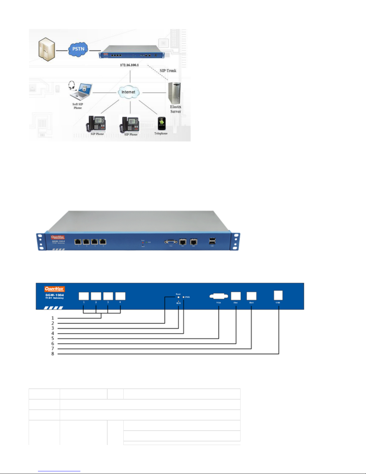
Figure 1-2-1Topological Graph
Product Appearance
The picture below is appearance of DGW-1004.
Figure 1-3-1 Product Appearance
Figure 1-3-2 Front Panel
Table 1-3-1 Description of Front Panel
Interface Function Color Work Status
1 Port 1-Port4 E1/T1 ports. The port numbers are different on different models, from 1 to 4.
2 Reset Reset button is used to restore the device.
3 RUN Register indicator Green Slow blinking(Green 2s and Flash 0.1s):Work normally
Fast blinking(Green 0.5s and Flash 0.5s): Work abnormally
Page 4

Fast blinking(Green 0.5s and Flash 0.5s): Work abnormally
No blinking: Dahdi Error
4 PWR Power Status indicator Green On: Power is on
Off: Power is off
5 VGA VGA monitor connector
6 Eth1 Network interface
7 Eth0 Network interface
8 USB USB interface
Figure 1-3-3 Backup Panel
The OpenVox DGW-100X series gateways provides one or two power supply, one power named DGW-100X ,the other is named DGW-100XR,
‘R’ stands for Reduntant.
Main Features
Based on Asterisk
®
Editable Asterisk configuration file
®
Wide selection of codecs and signaling protocol
Support 512 routing rules and flexible routing settings
Stable performance, flexible dialing, friendly GUI
Codecs support: G.711A, G.711U, G.729, G.723, G.722, GSM
Support ports group management
Support call status information
Support T.38/Pass-through fax
Support Auto Provision, SNMP V1/V2c/V3 and TR069
Echo Cancellation
Connect legacy PBX systems to low-cost VoIP services
Connect legacy PBX systems to remote sites over private VoIP links
Connect IP PBX systems to legacy TDM services
Physical Information
Table 1-5-1 Description of Physical Information
Weight 2842 g
Size 44cm*23cm*4.3cm
Temperature -40~85°C (Storage)
0~70°C (Operation)
Operation humidity 5%~95% non-condensing
Max power 20 W
Page 5
LAN port 1
WAN port 1
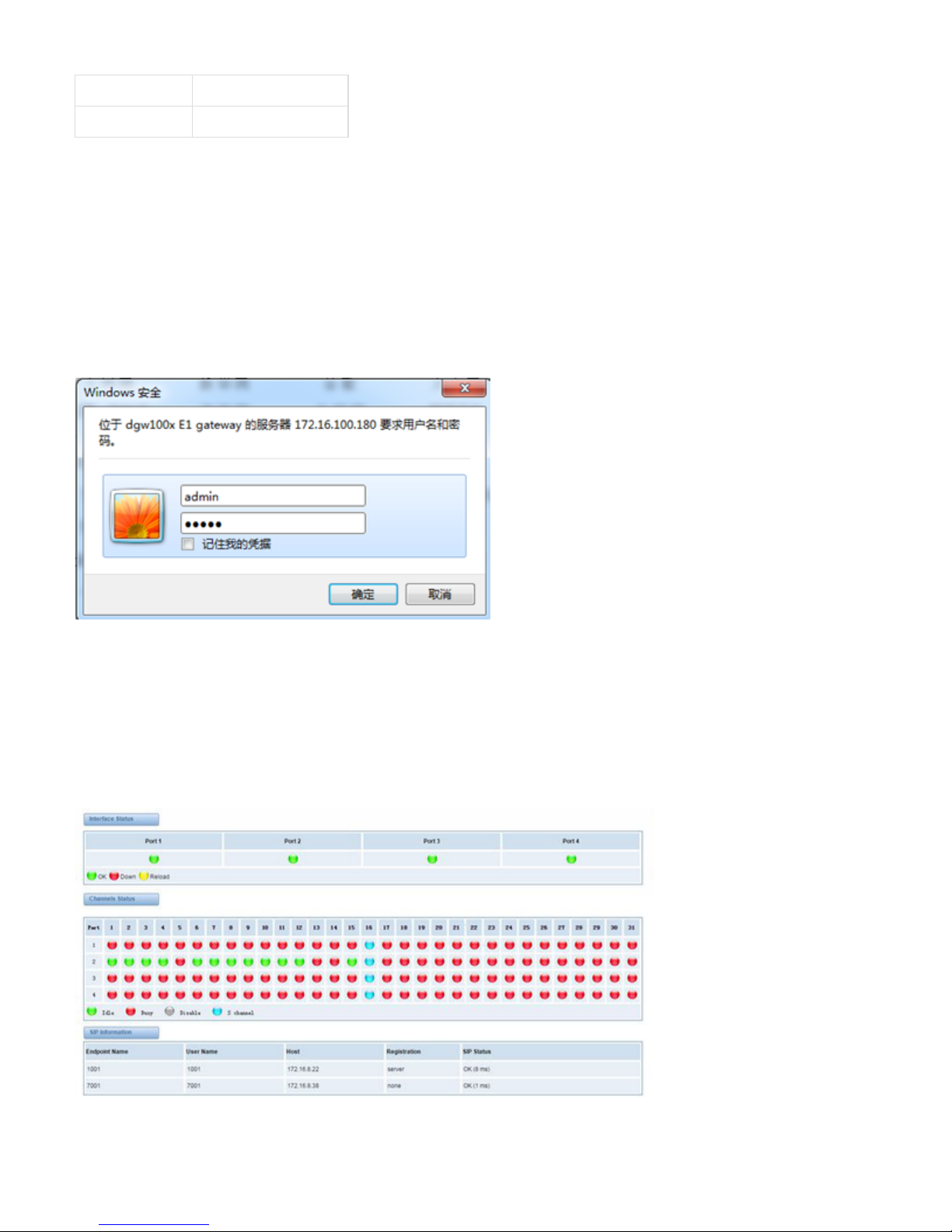
Software
Default IP: 172.16.100.1
Username: admin
Password: admin
Notice: Log in
Figure 1-6-1 LOG IN Interface
2. System
Status
On the “ ” page, you will find all Interface status, channels status, SIP, IAX2, Routing rules, and Network information.System Status
Page 6
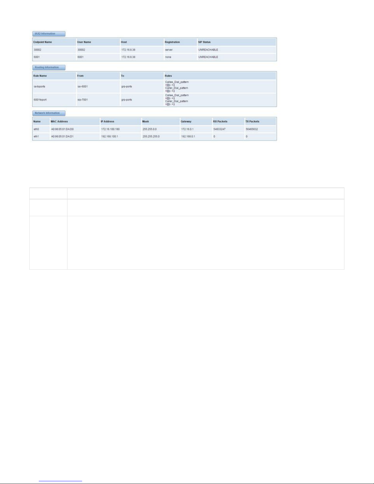
Figure 2-1-1 System Status
Table 2-1-1 Description of System Status
Options Definition
Interface
Status
Show the status of port, include "OK" and ”Down”. "Down" means no trunk line connected; "OK" means the trunk line of port
is available.
Channels Stat
us
Show the Channels status of port, include "Idle". "Busy". and “S channel”."Disable"
"Idle" means it is available;
"Busy" means the channel is busy;
"Disable" means it is unavailable;
“S channel” means signaling channel.
Call Status
The verbose of the system call status will be present on the “ ” page. You can select the specified T1/E1 port which you are care for.Call Status
Page 7
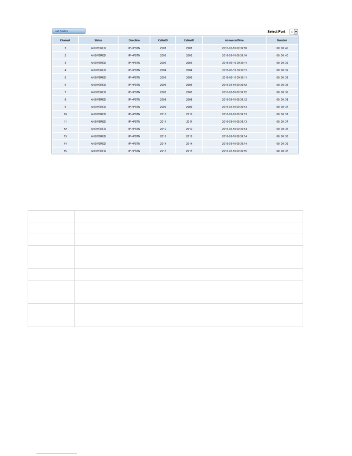
Figure 2-2-1 Verbose of call status
Time
Table 2-2-1Description of Time Settings
Options Definition
System Time Your gateway system time.
Time Zone The world time zone. Please select the one which is the same or the closest as your city.
POSIX TZ String Posix timezone strings.
NTP Server 1 Time server domain or hostname. For example, [ ].time.asia.apple.com
NTP Server 2 The first reserved NTP server. For example, [ ].time.windows.com
NTP Server 3 The second reserved NTP server. For example, [ ].time.nist.gov
Auto-Sync from NTP Whether enable automatically synchronize from NTP server or not. ON is enable, OFF is disable this function.
Sync from NTP Sync time from NTP server.
Sync from Client Sync time from local machine.
For example, you can configure like this:
Page 8

Figure 2-2-1 Time Settings
You can set your gateway time Sync from NTP or Sync from Client by pressing different buttons.
Login Settings
Your gateway doesn't have administration role. All you can do here is to reset what new username and password to manage your gateway. And it
has all privileges to operate your gateway. You can modify “Web Login Settings” and “SSH Login Settings”. If you have changed these settings,
you don’t need to log out, just rewriting your new user name and password will be OK. Also you can specify the web server port number.Usually
the web login default mode is “http and https”. For safety, you can switch to “only https” mode.
Table 2-3-1Description of Login Settings
Options Definition
User Name Your gateway does not have administration role.
All you can do here is defining the user name and password to manage your gateway.
And it has all privileges to operate your gateway .User Name: Allowed characters “-_+<>&0-9a-zA-Z”.Length:1-32
characters.
Password Allowed characters "-_+. <>&0-9a-zA-Z".
Length: 4-32 characters.
Confirm
Password
Please input the same password as 'Password' above.
Login Mode
Specify the web login mode: , . Default is http and https.http and https only https
Port Specify the web server port number. Do not use port 443 which is reserved for HTTPS.
Page 9

Figure 2-3-1 Login Settings
Notice: Whenever you do some changes, do not forget to save your configuration.
General
Language Settings
You can choose different languages for your system. If you want to change language, you can switch “Advanced” on, then “Download” your
current language package. After that, you can modify the package with the language you need. Then upload your modified packages, “Choose
File” and “Add”.
Figure 2-4-1 Language Settings
Scheduled Reboot
If switch it on, you can manage your gateway to reboot automatically as you like. There are four reboot types for you to choose, “By Day, By
Week, By Month and By Running Time”.
Figure 2-4-2 Reboot Types
Page 10

If use your system frequently, you can set this enable, it can helps system work more efficient.
Tools and Information
On the “Tools” pages, there are reboot Tools, update Firmware, upload Configuration, backup Configuration and Restore Configuration toolkits.
Reboot Tools
You can choose system reboot and Asterisk reboot separately.
Figure 2-5-1 Reboot Prompt
If you press “OK”, your system will reboot and all current calls will be dropped. Asterisk Reboot is the same.
Table 2-5-1 Instruction of reboots
Options Definition
System Reboot
This will turn off your gateway and then turn it back on. This will drop all current calls.
Asterisk Reboot This will restart Asterisk and drop all current calls.
Update Firmware
We offer 2 kinds of update types for you, you can choose System Update or System Online Update. System Online Update is an easier way to
update your system, if you choose that, you will see some information below.
Figure 2-5-2Prompt Information
Upload and Backup Configuration
If you want to update your system and remain your previous configuration, you can first backup configuration, then you can upload configuration
directly. That will be very convenient for you.
Page 11
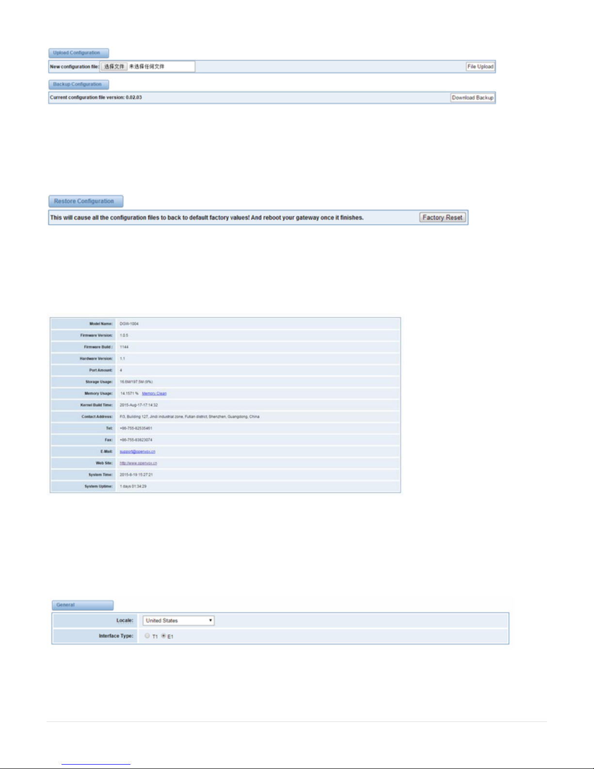
Figure 2-5-3 Upload and Backup
Restore Configuration
Sometimes there is something wrong with your gateway that you don’t know how to solve it, mostly you will select factory reset. Then you just
need to press a button, your gateway will be reset to the factory status.
Figure 2-5-4 Factory Reset
Information
On the “Information” page, there shows some basic information about the T1/E1 gateway. You can see software and hardware version, storage
usage, memory usage and some help information.
Figure 2-5-5 System Information
3. T1/E1
General
Figure 3-1-1 General Settings
Table 3-1-1 Definition of General Settings
Page 12

Local Your local. This will be used for the tone style. Used when in-call indications need to be generated such as ring back, busy,
congestion, and other call-oriented inband tone signals.
Interface
Type
It shows you the current type of port. It has two type:E1 and T1
Table 3-1-2 Definition of advanced interface type
Options Definition
Echo Cancellation Whether or not to enable echo cancellation
RX Gain
Gain for the RX (receive -into Asterisk)channel.Default:0.0
TX Gain
Gain for the TX (transmit -out of Asterisk Asterisk)channel.Default:0.0
Figure 3-1-2Port Details
Table 3-1-3 Definition of Port Details
Options Definition
Timing
Source
Timing Source indicate the ports as to which should be used to recover the clock.(0 for master mode, upper for client mode, small
number have higher priority )
Interface Choose a line type for this interface, all ports must be the same type.
Framing Framing method for this interface
Page 13

Coding Coding method for this interface
Line
Build-out
Line build-out represents the length of the cable form the port on this gateway to the next device.
CRC4 Enable cyclic redundancy checking for error checking on line. CRC-4 support is required for all network switches in Europe, but
many older switches and PBXs don’t support it.
Signaling It shows you what signaling the port uses.
Switch
Type
Only used for PRI
Description An optional description of this interface to be used for reference only.
ISDN-PRI
Advanced: Interface Type
Figure 3-2-1 Advanced: Interface Type
Table 3-2-1Definition of Interface Type
Options Definition
Echo Cancellation Whether or not to enable echo cancellation on this line
RX Gain Whole number
-24 to 24 and multiple of 3
Gain for the rx (receive -into Asterisk)channel.Default:0.0
TX Gain Whole number
-24 to 24 and multiple of 3
Gain for the tx(transmit -out of Asterisk Asterisk)channel.Default:0.0
ISDN: Signaling
Page 14

Figure 3-2-2 ISDN: Signaling
Table 3-2-2 Definition of Signaling
Options Definition
Q.SIG Channel
Mapping
Sets logical or physical channel mapping. In logical channel mapping, channels are mapped to 1-30.In physical channel
mapping, channels are mapped to 1-15,17-31,skipping the number used for the data channel, Default is physical.
Enable Caller ID Whether or not to use caller ID
PRI Dial Plan for
Dialed Number
PRI Dialplan: The ISDN-levei Type of Number (TON) or numbering plan, used for the dialed number. Leaving this as
‘unknown’ (the default) works for most cases. In some very unusual circumstances, you may need to set this to; ’dynamic’
or ‘redundant’
PRI Dial Plan for
Dialing Number
PRI Local Dialplan: Only RARELY used for PRI(sets the calling number’s numbering plan).In North America, the typical
use is sending the 10 digit; caller ID number and setting the prilocaldialplan to ‘national’ (the default).Only VERY rarely
will you need to change this.
Network Specific
Facility (NSF)
Messages
Some switches (AT&T especially) require network specific facility IE. Supported values are currently ‘none’,’sdn’,’
megacom’,’ tollfreemgacom’, ’ account’
Idle Bearer Reset Whether or not to reset unused B channels
Page 15

Idle Bearer Reset
Period
Sets the time in seconds between restart of unused B channels; defaults to ‘never’
Display Send Send/receive ISDN display IE options, the display options are a comma separated list of the following options:
Block:
Do not pass display text data.
Name_ initial:
Use display text in SETUP/CONNECT messages as the party name.
Name_ update:
Use display text in other messages (NOTIFY/FACILITY)for COLP name update.
Name:
Combined name_ initial and name_ update options.
Text:
Pas any unused display text data as an arbitrary display message during a call. Sent text goes out in default to ‘name’
Display Receive Send/receive ISDN display IE options. The display options are a comma separated list of the following options:
Block:
Do not pass display text data.
Name_ initial:
Use display text in SETUP/CONNECT messages as the party name.
Name_ update:
Use display text in other messages (NOTIFY/FACILITY) for COLP name update.
Name:
Combined name_ initial and name_ update options.
Text:
Pas any unused display text data as an arbitrary display message during a call. Sent text goes out in default to ‘name’
Overlap Dialing Enable overlap dialing mode--sending overlap digits.
Allow Progress
When Call
Released
Allow inband audio (progress) when a call is DISCONNECT Ted by the end of a PRI
Out-of-Band
Indications
PRI Out of band indications. Enable this to report Busy and congestion on a PRI using out_ of_ band notification. Inband
indication, as used by the gateway doesn’t seem to work with all telcos.
Facility-based
ISDN
Supplementary
Services
To enable transmission of facility-based ISDN supplementary services (such as caller name form CPE over facility),
enable this option. Cannot be changed on a reload.
Exclusive Channel
Selection
If you need to override the existing channels selection routine and force all PRI channels to be marked as exclusively
selected, set this to yes. priexclusive cannot be changed on a reload.
Ignore Remote
Hold Indications
If you wish to ignore remote hold indications (and use MOH that is supplied over the B channel) enable this option.
Block Outbound
Caller ID Name
Enable if you need to hide just the name and the number for legacy PBX use. Only applies to PRI channels.
Wait for Caller ID
Name
Support caller ID on call waiting
SS7
Page 16
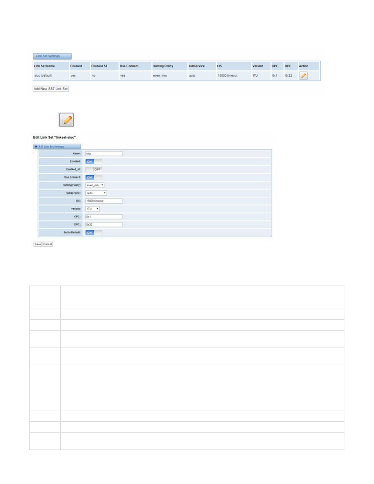
Link Set Settings
Figure 3-3-1 Link Set Settings
You can click button as shown below, when there are several link set, only one can be set to the default.
Figure 3-3-2 SS7 Link Set Settings
Table 3-3-1 Definition of SS7 Link Set Settings
options Definition
Name The linkset’s name
Enabled The linkset is enable or disable
Enabled_ st The end_of_pulsing (ST) is not used to determine when incoming address is complete
Use
Connect
Reply incoming call with CON rather than ACM and ANM
Hunting
Policy
The CIC hunting policy (even_mu, odd_lru, seq_lth, seq_htl) is even CIC numbers, most recently used
Subservice The subservice field: national (8), international l(0), auto or decimal/hex value; The auto means that the subservice is obtained
from first received SLTM.
t35 The value and action for t35. Value is in msec, action is either st or timeout; if you use overlapped dialing dial plan, you might
choose:t35=>4000,st
variant Running under SS7 standard
OPC The point code for this SS7 signaling point
DPC The destination point (peer) code
Set to
Default
Set the linkset as the default linke set
Page 17
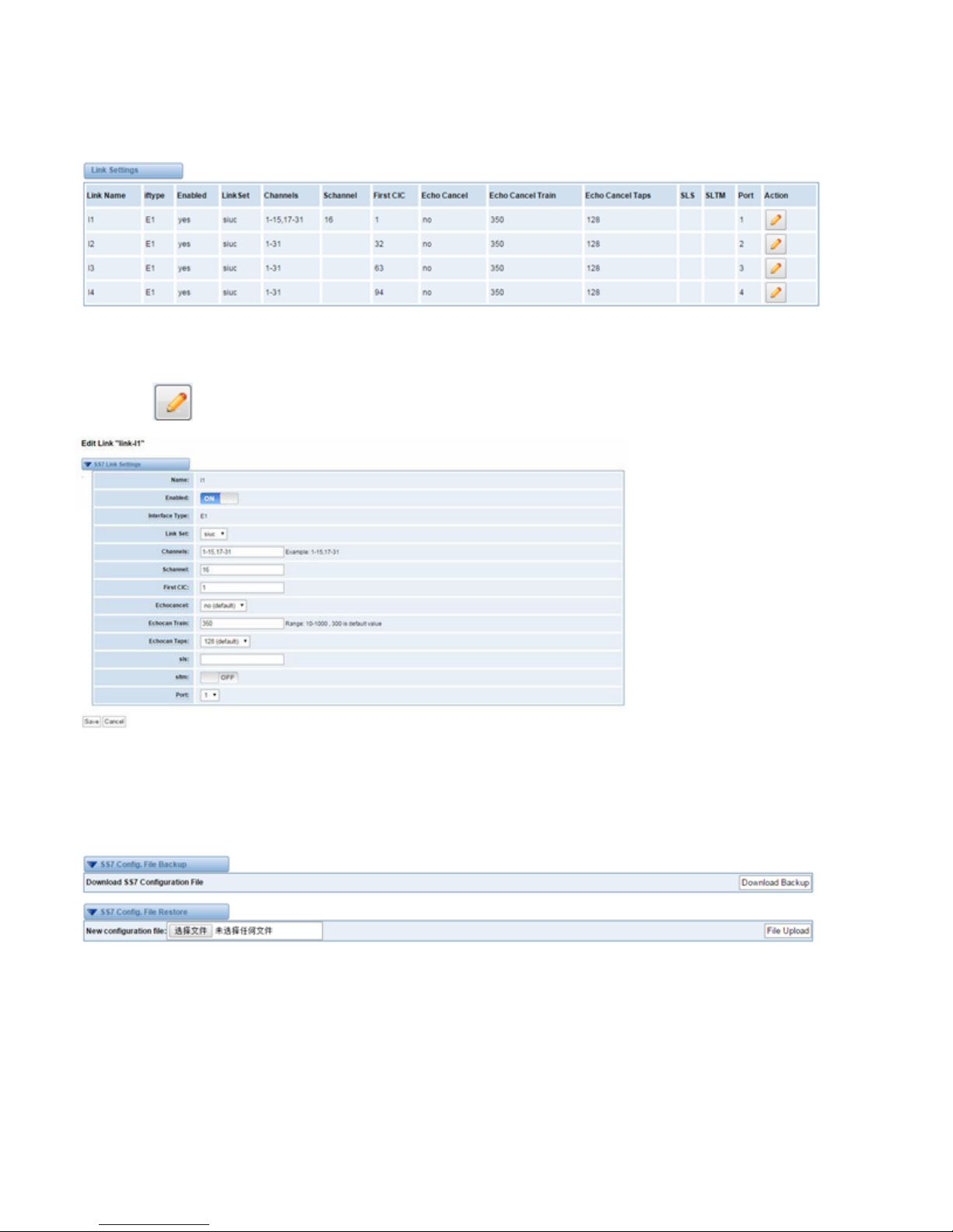
Link Settings
Figure 3-3-3 Link Settings
You can click button as shown below.
Figure 3-3-4 SS7 Link Settings
SS7 Config. File Backup and Restore
Figure 3-3-5 Config. File Backup and Restore
MFC/R2
Advanced: Interface Type
Page 18
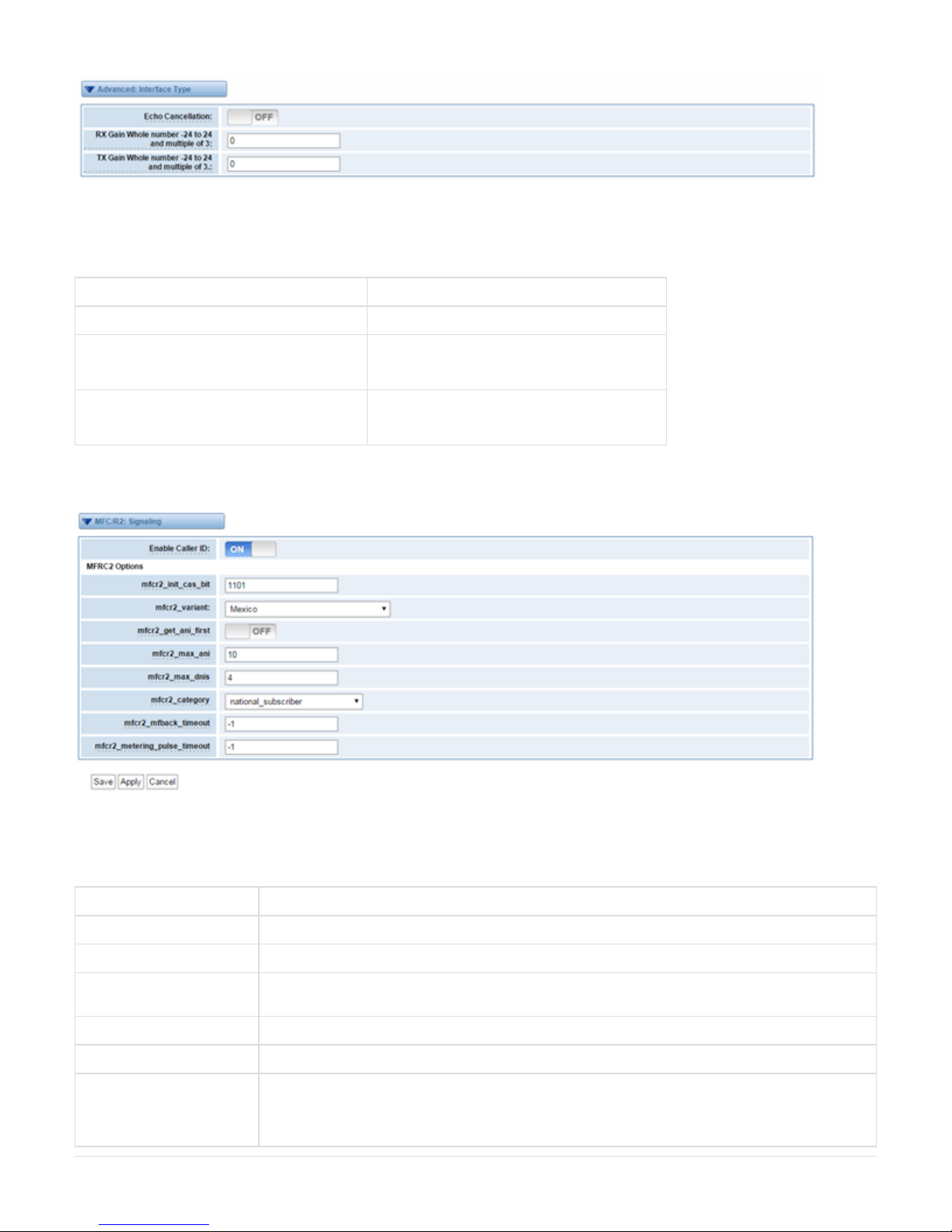
Figure 3-4-1 Advanced: Interface Type
Table 3-4-1 Definition of Interface Type
options Definition
Echo Cancellation Whether or not enable echo cancellation on this line
RX Gain Whole number -24 to 24 and multiple of 3 Gain for the rx (receive_ into Asterisk) channel.
Default:0.0
TX Gain Whole number -24 to 24 and multiple of 3 Gain for the tx (receive_ into Asterisk) channel.
Default:0.0
MFC/R2: Signaling
Figure 3-4-2 MFC/R2: Signaling
Table 3-4-2Definition of MFC/R2: Signaling
options Definition
Enable Caller ID Whether or not to use caller ID
mfcr2_init_cas_bit The initial position of the CAS bits (also known as ABCD bits)
mfcr2_get_ani_first Whether or not to get ANI before getting DINS; some telcos require ANI first some others do not care; if this
go wrong, change this value
mfcr2_max_ani Max amount of ANI to ask for
mfcr2_max_dnis Max amount of DNIS to ask for
mfcr2_category Usually national-subscriber works just fine; you can change this setting from the dialplan ; by setting the
variable MFCR2-CATEGORY;(remembering ti set-MFCR2-CATEGORY from originating
channels);MFCR2-CATEGORY will also be a variable in your context; on incoming calls set to the value
received from the far end;mfcr2-category=national-subscriber
Page 19
mfcr2_mfback_timeout MFC/R2 value in milliseconds for the MF timeout
mfcr2_metering_pulse_timeout MFC/R2 value in milliseconds for the metering pulse timeout
4.VOIP
VOIP Endpoints
SIP Endpoints
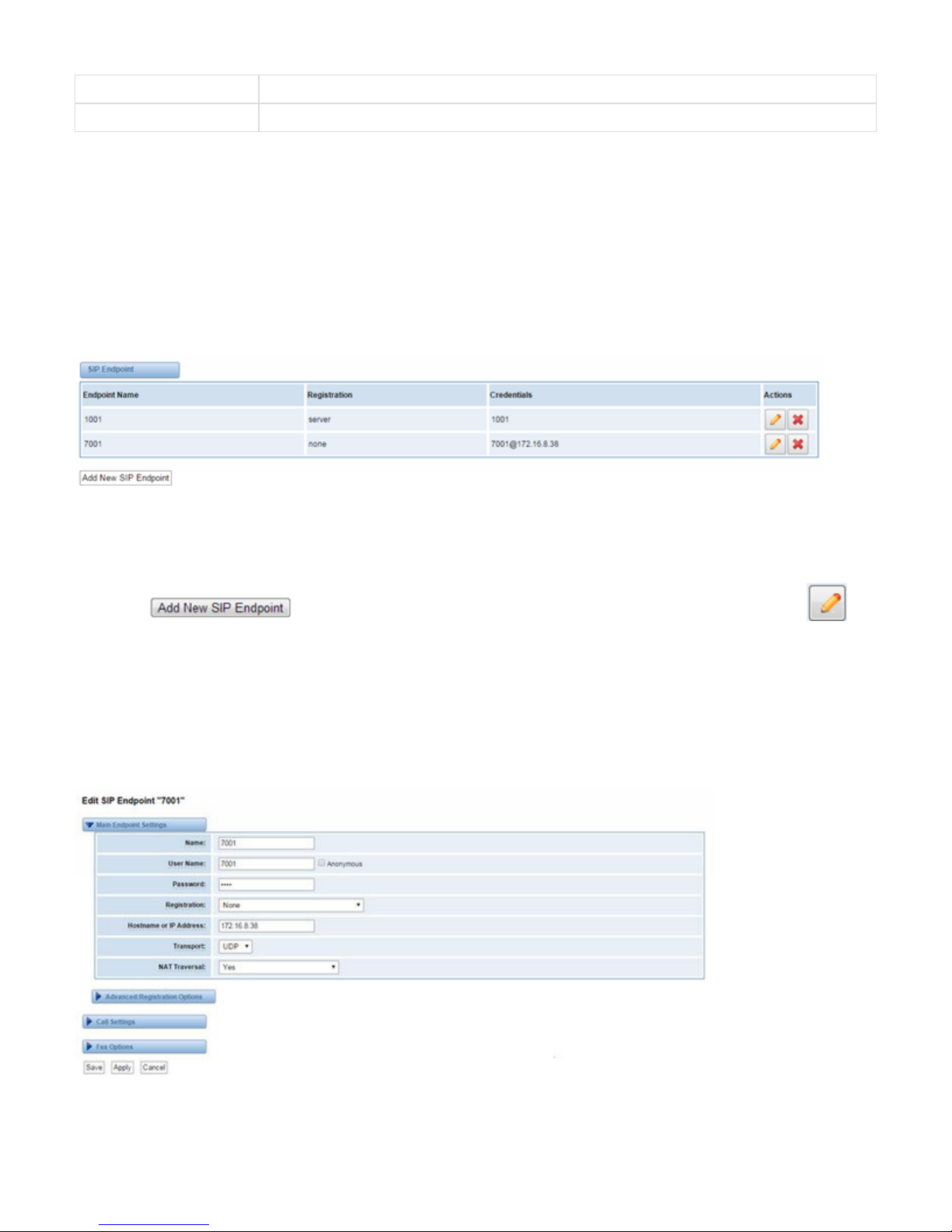
This page shows everything about your SIP, you can see status of each SIP.
Figure 4-1-1 SIP Status
Main Endpoint Settings
You can click button to add a new SIP endpoint, and if you want to modify existed endpoints, you can click butt
on.
There are 3 kinds of registration types for choose. You can choose Anonymous, Endpoint registers with this gateway or This gateway registers
with the endpoint.
You can configure as follows:
If you set up a SIP endpoint by registration “None” to a server, then you can’t register other SIP endpoints to this server. (If you add other SIP
endpoints, this will cause Out-band Routes and Trunks confused.)
Figure 4-1-2 None Registration
For convenience, we have designed a method that you can register your SIP endpoint to your gateway, thus your gateway just work as a server.
Page 20
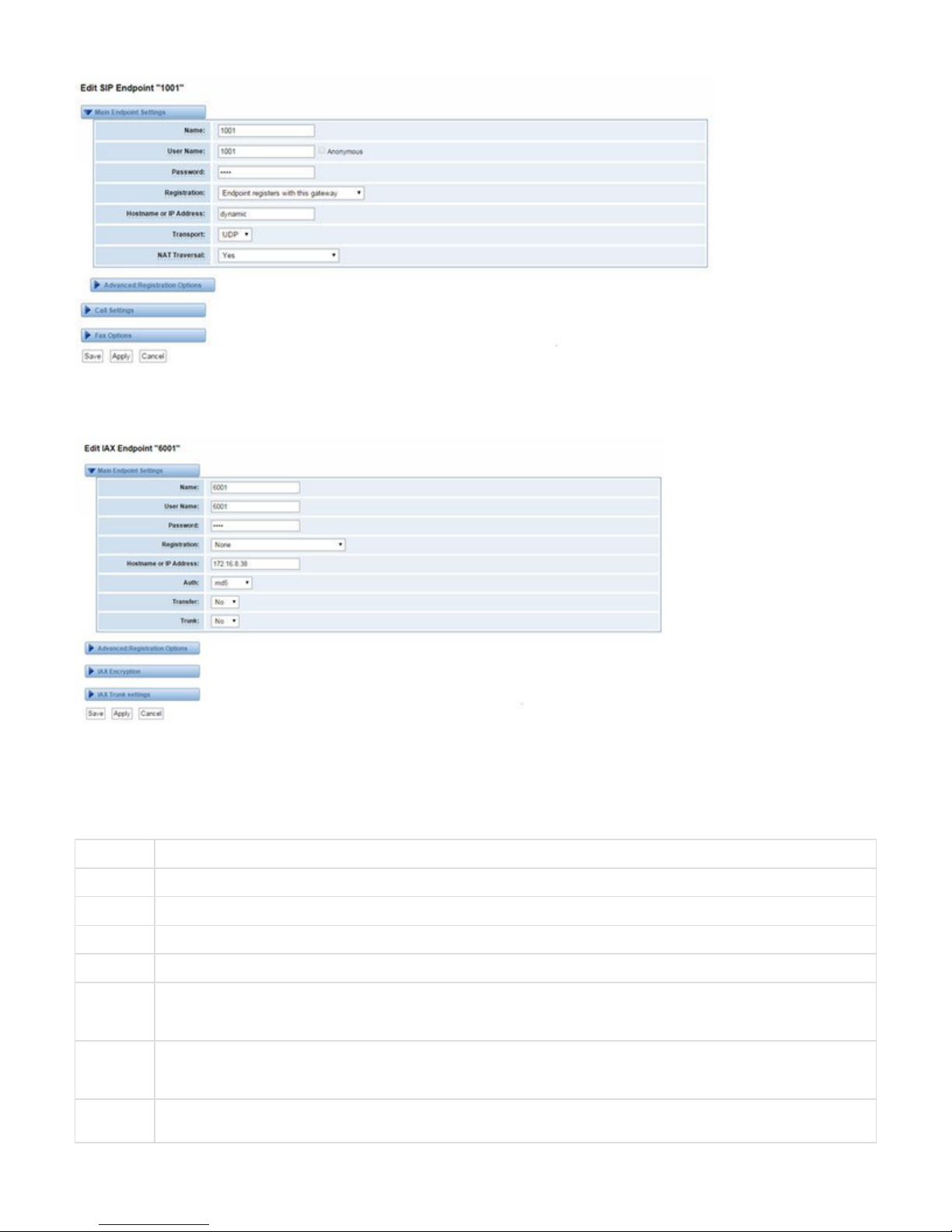
Figure 4-1-3 Endpoint Register with Gateway
Also you can choose registration by “This gateway registers with the endpoint”, it’s the same with “None”, except name and password.
Figure 4-1-4 This Gateway Register with the Endpoint
Table 4-1-1 Definition of SIP Options
Options Definition
Name A name which is able to read by human. And it’s only used for user’s reference.
Username User name the end point use to authenticate with the gateway
Password Password the endpoint will use to authenticate with the gateway. Allowed characters
Registration Whether this endpoint will registers with this gateway.
Hostname
or IP
Address
IP address or hostname of the endpoint or 'dynamic' if the endpoint has a dynamic IP address. This will require registration.
Notice: if the input here is hostname and your DNS has changed, you must reboot asterisk.
Transport This sets the possible transport types for outgoing. Order of usage, when the respective transport protocols are enabled, is UDP,
TCP, TLS. The first enabled transport type is only used for outbound messages until a Registration takes place. During the peer
Registration the transport type may change to another supported type if the peer requests so.
NAT
Traversal
Addresses NAT-related issues in incoming SIP or media sessions.
Page 21

Advanced: Registration Options
Table 4-1-2 Definition of Registration Options
Options Definition
Authentication User A username to use only for registration.
Register Extension When Gateway registers as a SIP user agent to a SIP proxy (provider), calls from this provider connect to this local
extension.
From User A username to identify the gateway to this endpoint.
From Domain A domain to identify the gateway to this endpoint.
Remote Secret A password which is only used if the gateway registers to the remote side.
Port The port number the gateway will connect to at this endpoint.
Qualify Whether or not to check the endpoint's connection status.
Qualify frequency
Frequency
How often, in seconds, to check the endpoint's connection status.
Outbound Proxy A proxy to which the gateway will send all outbound signaling instead of sending signaling directly to endpoints.
Call Settings
Table 4-1-3 Definition of Call Options
Options Definition
DTMF Mode Set default DTMF Mode for sending DTMF. Default: rfc2833.
Other options: 'info', SIP INFO message (application/ dtmf-relay);
'Inband', Inband audio (require 64kbit codec - alaw, ulaw).
Trust Remote-Party-ID Whether or not the Remote-Party-ID header should be trusted.
Send Remote-Party-ID Whether or not to send the Remote-Party-ID header.
Caller ID Presentation Whether or not to display Caller ID.
Advanced Timer Settings
Table 4-1-4 Definition of Timer Options
Options Definition
Default T1 Timer This timer is used primarily in INVITE transactions. The default for Timer T1 is 500ms or the measured run-trip time
between the gateway and the device if you have qualify=yes for the device.
Page 22

Call Setup Timer If a provisional response is not received in this amount of time, the call will auto-congest. Defaults to 64 times the default
T1 timer.
Session Timers Session-Timers feature operates in the following three modes: originate, Request and run session-timers always; accept,
run session-timers only when requested by other UA; refuse, do not run session timers in any case.
Minimum Session Minimum session refresh interval in seconds. Default is 90secs.
Maximum
Session Refresh
Interval
Maximum session refresh interval in seconds. Defaults to 1800s.
Session
Refresher
The session refresher, uac or uas. Defaults to uas.
Advanced: Signaling Settings
Table 4-1-5Definition of Signaling Options
Options Definition
Progress
Inband
If we should generate in-band ringing. Always use ‘never’ to never use in-band signalling,
Even in cases where some buggy devices might not render it. Valid values: yes, no, never. Default: never.
Append
user=phone
to URI
Whether or not to add;’ user=phone’ to URIs that contain a valid phone number.
Add Q.850
Reason
Headers
Whether or not to add Reason header and to use it if it is available.
Honor SDP
Version
By default, the gateway will honor the session version number in SDP packets and will only modify the SDP session if the
version number changes. Turn This option off to force the SDP session version number and treat all SDP data as new data.
This is require for devices that send non-standard SDP packets (observed with Microsoft OC S).By default
This option is on.
Allow
Transfers
Whether or not to globally enable transfers. Choosing ‘no’ will disable all transfers (unless enable in peers or users). Default is
enabled.
Allow
Promiscuous
Redirects
Whether or not to allow 302 or REDIR to non-local SIP address .Note that promiscredir when redirects are made to the local
system will cause loops since this gateway is incapable of performing a ‘hairpin’ call.
Max
Forwards
Setting for the SIP Max-Forwards header (loop prevention).
Send
TRYING on
REGISTER
Send 100 Trying when the endpoint registers.
Table 4-1-6 Definition of Fax Options
Options Definition
Mode Working mode T.38 and T.30
Enabled Enabled
Error
Correction
Error Correction
Page 23
Max
Datagram
In some cases,T.38 endpoints will provide a T38FaxMxDatagram value (during T.38 setup) that is based on an incorrect
interpretation of the T.38 recommendation, and result in failures because Asterisk does not believe it can send T.38 packets of a
reasonable size to that endpoint (Cisco media gateway are one example of this situation).In these cases, during a T.38 call you
will see warring messages on The console/in the logs from the Asterisk UDPTL stack complaining about lack of buffer space to
send T.38FaxMaxDatagram value specified by the other end[point, and use a configured value instead.
Fax
Detect
FAX detection will cause the SIP channel to jump to the ‘faX’ extension (if exists) based one or more events being detected. The
events that can be detected are an incoming CNG tone or an incoming T.38 re-INVITE request.
Fax
Activity
activate T38 fax gateway with ‘timeout’ seconds
Fax
Timeout
activate T38 fax gateway with ‘timeout’ seconds
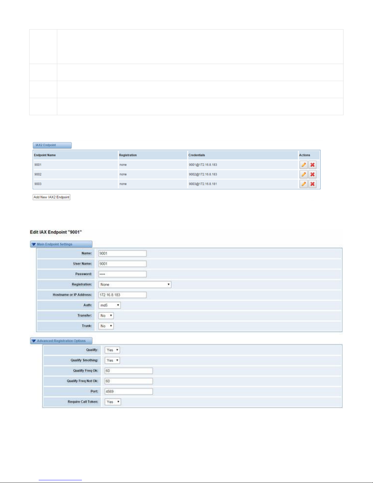
IAX2 Endpoint
Figure 4-1-5 IAX2 Endpoint
You can click button as shown below
Page 24
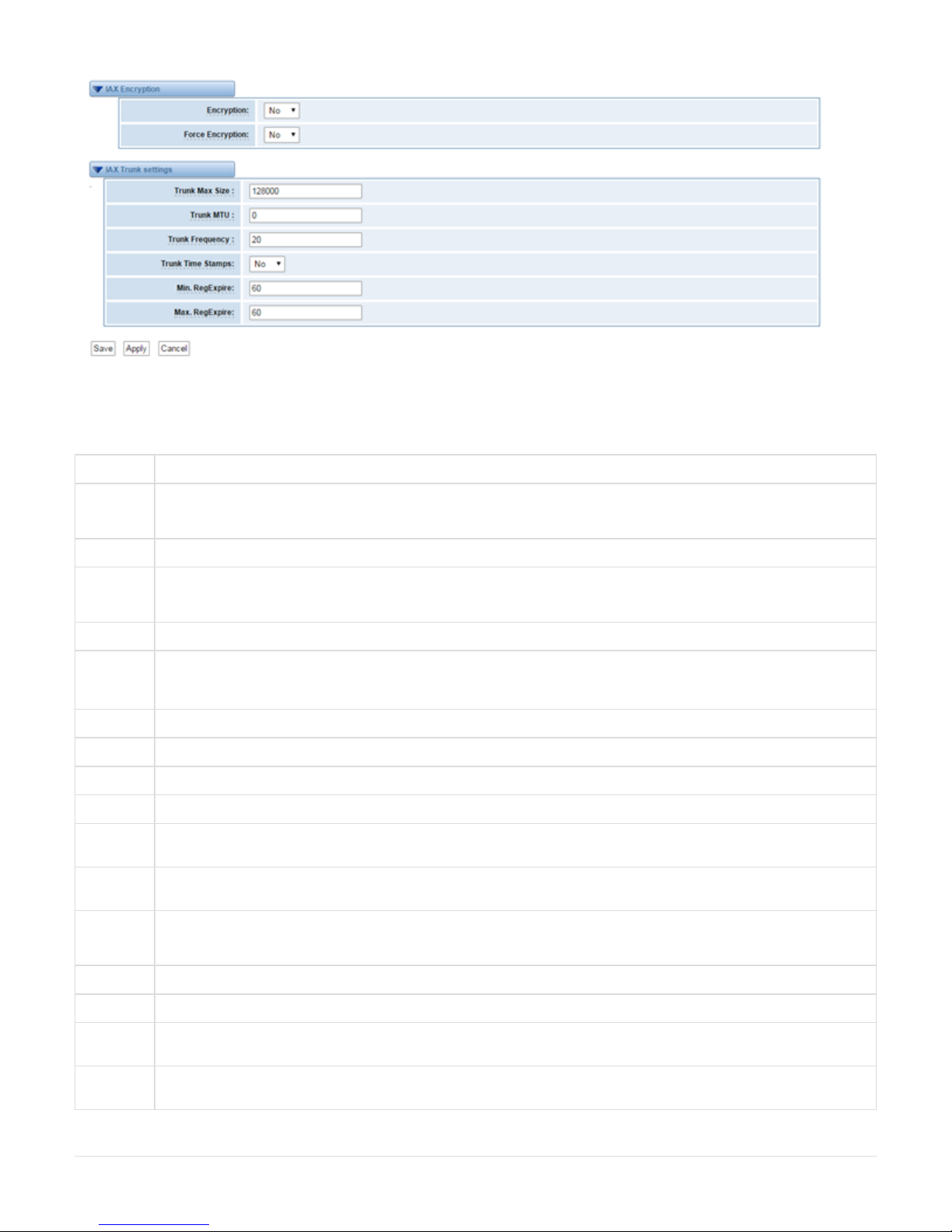
Figure 4-1-6 Edit IAX Endpoint "9001"
Table 4-1-6 Definition of IAX2 Endpoint
Options Definition
Name A name which is able to read by human.
And it’s only used for user’s reference.
User name User name the endpoint will use to authenticate with the gateway
Password Password the endpoint will use to authenticate with gateway.
Allowed characters
Registration Whether this endpoint will register to this gateway or this gateway to the endpoint.
Hostname
or IP
Address
IP address or hostname of the endpoint or ‘dynamic’ if the endpoint has a dynamic IP address. This will require registration.
Notice: If the input here is hostname and your DNS has changed, you must reboot asterisk.
Auth Authentication method for connections
Transfer Disable or not IAX2 native transfer
Trunk Use IAX2 trunking with this host
Qualify Whether or not to check the endpoint’s connection status.
Qualify
Smothing
Use an average of the last two PONG result to reduce falsely detected LAGGED host. The default is ‘no’.
Qualify
Freq Ok
How frequently to ping the peer when everything seems to be OK, in milliseconds.
Qualify
Freq not Ok
How frequently to ping the peer when it’s either;
LAGGED or UNAVAILABLE, in milliseconds.
Port The port number the gateway will connect to at this endpoint.
Encryption Enable IAX2 encryption. The default is no.
Force
Encryption
Force encryption insures no connection is established unless both sides support encryption. By turning this option on, encryption
is automatically; turned on as well. The default is no.
Trunk Max
Size
Defaults to 128000 bytes, which supports up to 800; calls of ulaw at 20ms a frame.
Page 25

Trunk MTU With a large amount of traffic on IAX2 trunk, there is a risk of bad voice quality when allowing the Linux system to handle
fragmentation of UDP packets.
Depending on the side of each payload, allowing the OS to handle fragmentation may not be very efficient. This setting sets the
maximum transmission unit for AIX2 UDP trunking. The default is 1240 bytes which means if a trunk’s payload is over 1240
bytes for every 20ms it will be broken into multiple 1240 bytes messages. Zero disables this functionality and let’s the OS handle
fragmentation.
Trunk
Frequency
How frequently to send trunk msgs (in ms). This is 20ms by default.
Trunk Time
Stamps
Should we send timestamps for the individual sub_frames within trunk frames? There is a small bandwith use for these (less
than 1kbps/call), but they ensure that frame timestamps get sent end-to-end properly. If both ends of all your trunks go directly to
TDM, _and_your trunkfreq equals the frame length for your codecs, you can probably suppress these. The receiver must also
need to have it enabled.
Min.
RegExpire
Minimum amounts of time that IAX2 peers can request as a registration interval (in seconds).
Max.
RegExpire
Maximum amounts of time that IAX2 peers can request as a registration expiration interval(in seconds).
Advanced SIP Settings
Networking
Table 4-2-1 Definition of Networking Options
Options Definition
UDP Bind
Port
Choose a port on which to listen for UDP traffic.
Enable TCP Enable server for incoming TCP connection (default is no).
TCP Bind
Port
Choose a port on which to listen for TCP traffic.
TCP
Authentication
Timeout
The maximum number of seconds a client has to authenticate. If the client does not authenticate before this timeout expires,
the client will be disconnected.(default value is: 30 seconds).
TCP
Authentication
Limit
The maximum number of unauthenticated sessions that will be
allowed to connect at any given time (default is: 50).
Enable
Hostname
Lookup
Enable DNS SRV lookups on outbound calls Note: the gateway only uses the first host in SRV records Disabling DNS SRV
lookups disables the ability to place SIP calls based on domain names to some other SIP users on the Internet specifying a
port in a SIP peer definition or when dialing outbound calls with suppress SRV lookups for that peer or call.
Enable
Internal SIP
Call
Whether enable the internal SIP calls or not when you select the registration option "Endpoint registers with this gateway".
Internal SIP
Call Prefix
Specify a prefix before routing the internal calls.
Advanced: NAT Settings
Table 4-2-2 Definition of NAT Settings Options
Page 26

Options Definition
Local Network Format:192.168.0.0/255.255.0.0 or 172.16.0.0./12. A list of IP address or IP ranges which are located inside a NATed
network. This gateway will replace the internal IP address in SIP and SDP messages with the external IP address when a
NAT exists between the gateway and other endpoints.
Local Network
List
Local IP address list that you added.
Subscribe
Network Change
Event
Through the use of the test_stun_monitor module, the gateway has the ability to detect when the perceived external network
address has changed. When the stun_ monitor is installed and configured, chan_sip will renew all outbound registrations
when the monitor detects any sort of network change has occurred. By default this option is enabled, but only takes effect
once res_stun_monitor is configured. If res_stun_monitor is enabled and you wish to not generate all outbound registrations
on a network change, use the option below to disable this feature.
Match External
Address Locally
Only substitute the exeternaddr or externhost setting if it matches
Dynamic
Exclude Static
Disallow all dynamic hosts from registering as any IP address used for staticly defined hosts .This helps avoid the
configuration error of allowing your users to register at the same address as a SIP provide.
Externally
Mapped TCP
Port
The externally mapped TCP port, when the gateway is behind a static NAT or PAI
External
Address
The external address (and optional TCP port) of the NAT. External address=hostname [:port] specifies a static
address[:port] to be used in SIP and SDP messages. Examples: External address=12.34.56.78 External
address=12.34.56.78.9900
External
Hostname
The external hostname (and optional TCP port) of the NAT.
External Hostname=hostname[:port] is similar to
“External address”. Examples:
External Hostname=foo.dyndns.net
Hostname
Refresh Interval
How often to perform a hostname lookup. This can be useful when your NAT device lets you choose the port mapping, but
the IP address is dynamic. Beware, you might suffer from service disruption when the name server resolution fails.
Advanced: RTP Settings
Table 4-2-3 Definition of RTP Settings Options
Options Definition
Start of RTP Port Range Start of range of port numbers to be used for RTP.
End of RTP port Range End of range of port numbers to be used for RTP.
Parsing and Compatibility
Table 4-2-4 Instruction of Parsing and Compatibility
Page 27

Options Definition
Strict RFC
Interpretation
Check header tags, character conversion in URIs, and multiline headers for strict SIP compatibility(default is yes)
Send
Compact
Headers
Send compact SIP headers
SDP Owner
Allows you to change the username filed in the SDP owner string.
This filed MUST NOT contain spaces.
Disallowed SIP
Methods
When a dialog is started with another SIP endpoint, the other endpoint should include an Allow header telling us what SIP
methods the endpoint implements. However, some endpoint either do not include an Allow header or lie about what
methods they implement. In the former case, the gateway makes the assumption that the endpoint support all known SIP
methods. If you know that your SIP endpoint does not provide support for a specific method, then you may provide a list of
methods that your endpoint does not implement in the disallowed_ methods option. Note that if your endpoint is truthful
with its Allow header, then there is need to set this option.
Shrink Caller ID The shrinkcallerid function removes '(', ' ', ')', non-trailing '.', and '-' not in square brackets. For example, the caller id value
555.5555 becomes 5555555 when this option is enabled. Disabling this option results in no modification of the caller id
value, which is necessary when the caller id represents something that must be preserved. By default this option is on.
Maximum
Registration
Expiry
Maximum allowed time of incoming registrations and subscriptions (seconds).
Minimum
Registration
Expiry
Minimum length of registrations/subscriptions (default 60).
Default
Registration
Expiry
Default length of incoming/outgoing registration.
Registration
Timeout
How often, in seconds, to retry registration calls. Default 20 seconds.
Number of
Registration
Number of registration attempts before we give up.0=continue forever, hammering the other server until it accepts the
registration. Default is 0 tries, continue forever.
Security
Table 4-2-5 Instruction of Security
Option Definition
Page 28

Match
Auth
Username
If available, match user entry using the 'username' field from the
authentication line instead of the 'from' field.
Realm
Realm for digest authentication. Realms MUST be globally unique according to RFC 3261. Set this to your host name or domain
name.
Use
Domain
as Realm
Use the domain from the SIP Domains setting as the realm. In this case, the realm will be based on the request 'to' or 'from'
header and should match one of the domain. Otherwise, the configured 'realm' value will be used.
Always
Auth
Reject
When an incoming INVITE or REGISTER is to be rejected, for any reason, always reject with an identical response equivalent
to valid username and invalid password/hash instead of letting the requester know whether there was a matching user or peer
for their request. This reduces the ability of an attacker to scan for valid SIP usernames. This option is set to 'yes' by default.
Authenticate
Options
Requests
Enabling this option will authenticate OPTIONS requests just like INVITE requests are. By default this option is disabled.
Allow Guest
Calling
Allow or reject guest calls (default is yes, to allow). If your gateway is connected to the Internet and you allow guest calls, you
want to check which services you offer everyone out there, by enabling them in the default context.
Media
Table 4-2-6 Instruction of Media
Options Definition
TOS for SIP Packets
Sets type of service for SIP packets
TOS for RTP Packets
Sets type of service for RTP packets
Codec Settings
Select codecs from the list below.
Page 29

Figure 4-2-1 Codec Settings
Advanced IAX2 Settings
Table 4-3-1 Instruction of General
Options Definition
Bind Port Bind port and bindaddr may be specified
Enable
IAXCompat
More than once to bind to multiple addresses, but the first will be the default.
Enable
Nochecksums
Set iaxcompat to yes if you plan to use layered switches or some other scenario which may cause some delay when doing a
lookup in the dialplan. It incurs a small performance hit to enable it. This option cause Asterisk to spawn a separate thread
when it receives an IAX DPREQ (Dialplan Request) instead of blocking while it waits for a response.
Enable Delay
Reject
Disable UDP checksums (if no checksums is set, then no checksums will be calculated/checked on system supporting the
feature)
ADSI ADSI (Analog Display Services Interface) can be enable if you have (or may have) ADSI compatible CPE equipment.
SRV Loopup Whether or not to perform an SRV lookup on outbound calls
AMA Flags You may specify a global default AMA flag for iaxtel calls. These flags are used in the generation of call detail records.
autokill If we don’t get ACK to our NEW within 2000ms,and autokill is set to yes, then we cancel the whole thing(that’s enough time for
one retransmission only ).This is used to keep things from stalling for a long time for a host that is not available for bad
connections.
Language You may specify a global default language for users. This can be specified also on a per-user basis. If omitted, will fallback to
English(en)
Account
Code
You may specify a default account for Call Detail Records (CDRs) in addition specifying on a per-user basis.
Table 4-3-2 Instruction of Music on Hold
Options Definition
Mohsuggest The ‘Mohsuggest’ option specifies which music on hold class to suggest to the peer channel when this channel place the peer
on hold. It may be specified globally or on a per-user or per-peer basis.
Mohinterpret You may specify a global default language for users. This can be specified also on a per-user basis. If omitted, will fallback to
English(en)
Table 4-3-3 Instruction of Codec Settings
Page 30

Options Definition
Band
Width
Specify bandwith of low, medium, or high to control which codes are used in general
Disallow Fine tune codes here using “allow” and “disallow” clause with specific codes
Allow Fine tune codes here using “allow” and “disallow” clause with specific codes
Codec
Priority
Codec priority controls the codec negotiation of an inbound IAX2 call. This option is inherited to all user entity separately which
will override the setting in general.
Table 4-3-4 Instruction of Jitter Buffer
Options Definition
Jitter Buffer Global default as to whether you want the jitter buffer at all
Force Jitter
Buffer
In the ideal world, when we bridge VoIP channels we don’t want to jitter buffering on the switch, since the endpoints can
each handle this. However, some endpoints may have poor jitter buffers themselves, so this option will force to always jitter
buffer, even in this case.
Max Jitter
Buffers
A maximum size for the jitter buffer
Resyncthreshold When the jitter buffer notice a significant change in delay that continue over a few frames, it will resync, assuming that the
change in delay was caused by a timestamping mix-up. The threshold for noticing a change in delay is measured as twice
the measured jitter plus this resync threshold.
Max Jitter
Interps
The maximum number of interpolation frames the jitter buffer should return in a row. Since some clients do not send
CNG/DTX frames to indicate silence, the jitter buffer will assume silence has begun after returning this many interpolations.
This prevents interpolating throughout a long silence.
Jitter Target
Extra
Number of milliseconds by which the new jitter buffer will pad its size. The default is 40, so without modification, the new
jitter buffer will set its size to the jitter value may help if your network normally has low jitter, but occasionally has spikes.
Table 4-3-5 Instruction of Misc Settings
Options Definition
IAX Thread Count Establishes the number of iax helper thread to handle I/O
IAX Max Thread Count Establishes the number of extra dynamic threads that may by spawned to handle I/O
Max Call Number The ‘maxcallnumbers’ option limits the amount of call numbers allowed for each individual remote IP
address. Once an IP address reaches its call number limit, no more new connections are allowed until the
previous ones close. This option can be used in a peer definition as well, but only takes effect for the IP of a
dynamic peer after it completes registration.
MaxCallNumbers_Nonvalidated The ‘maxcallnumbers-nonvalidated’ is used to set the combined number of call numbers that can be
allocated for connections where call token validation has been disabled. Unlike the ‘maxcallnumbers’ option,
this limit is not separate for each individual IP address. Any connection resulting in a non-call token validated
call number being allocated contributes to this limit. For use cases, see the call should be sufficient in most
cases.
Table 4-3-6 Instruction of Quality of Service
Options Definition
Tos Type of service
Cos Class of service
Advanced Fax Settings
Table 4-4-1 Instruction of Quality of Fax Settings
Page 31

Options Definition
Udptl Start DPTL start configure addresses
Udptl End DPTL end configure addresses
Udptl Checksums Whether to enable or disable UDP checksums on UDPTL traffic
Udptl Fec Entries The number of error correction entries in a UDPTL packet
Udptl Fec Span The span over which parity is calculated for FEC in a UDPTL packet
Use Even Ports Some VoIP providers will only accept an offer with an even-numbered UDPTL port. Set this option so that Asterisk
will only attempt to use even-numbered ports when negotiating T.38. Default is no.
Maximum
Transmission Rate
Maximum Transmission Rate
Minimum Transmission
Rate
Minimum Transmission Rate
Send Progress/Status
events to manager
session
Manager events with ‘call’ class permissions will receive events indicating the steps to initiate a fax session. Fax
completion events are always sent to manager sessions with ‘call’ class permissions, regardless of the value of this
option.
Modem Capabilities Set this value to modify the default modem options. Defasult:v17,v27,v29
ECM Enable/disable T.30 ECM(error correction mode) by default
5. Routing
The gateway embraces the flexible and friendly routing settings for user. It supports up to 512 routing rules and about 100 pairs of
calleeID/callerID manipulations can be set in a rule. It support DID function (The usage of DID function: How to use DID function with OpenVox
T1/E1 Gateway). The gateway support trunk group and trunk priority management.
Figure 5-1-1 Routing Rules
You are allowed to set up new routing rule by , and after setting routing rules, move rules’ order by pulling up and
down, click button to edit the routing and to delete it. Finally click the button to save what you set. sho
ws current routing rules. Otherwise you can set up unlimited routing rules.
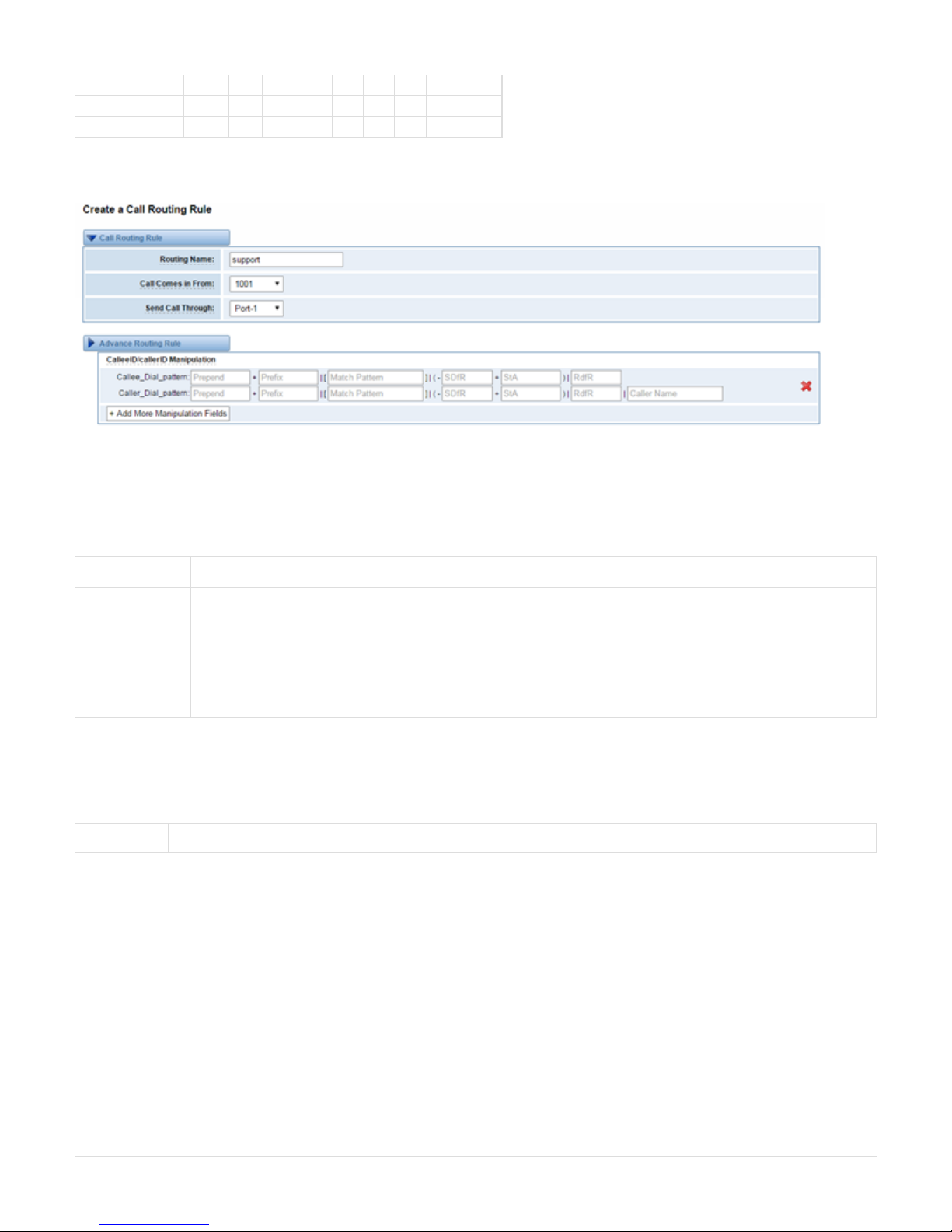
Call Routing Rule
There is an example for Routing rules number conversion, it transform calling, called number at the same time. Suppose you want eleven
numbers start at 159 to call the eleven numbers of start at 136. Calling transform delete the three numbers from left, then writing number 086 as
prefix, delete the last four numbers, and then add number 0755 at the end, it will show caller name is . Called transform adds 086China Telecom
as prefix , and Change the last two number to 88.
Page 32
processing rules prepend prefix Match pattern SdfR StA RdfR Caller Name
Calling Transformation 086 159 ЧЧЧЧЧЧЧЧ 4 0755 China Telecom
Called transformation 086 136 ЧЧЧЧЧЧЧЧ 2 88 N/A
Figure 5-1-2
You can click button to set up your routings.
Figure 5-1-3 Example of Set Up Routing Rule
The figure above realizes that calls from “support” SIP endpoint switch you have registered will be transferred to Port-1. When “Call Comes in
From” is 1001, “prepend”, “prefix” and “match pattern” in “Advanced Routing Rule” are ineffective, and just “CallerID” option is available.
Table 5-1-1 Definition of Routing Options
Options Definition
Routing Name The name of this route. Should be used to describe what types of calls this route matches (for example, 'SIP2Ports' or
'Ports2SIP').
Call Comes in
From
The launching point of incoming calls.
Send call Through The destination to receive the incoming calls.
Table 5-1-2 Description of Advanced Routing Rule
Options Definition
Page 33
Dial Patterns
that will use
this Route
A Dial Pattern is a unique set of digits that will select this route and send the call to the designated trunks. If a dialed pattern
matches this route, no subsequent routes will be tried. If Time Groups are enabled, subsequent routes will be checked for
matches outside of the designated time(s).
Rules:
matches any digit from 0-9X
matches any digit from 1-9Z
matches any digit from 2-9N
[1237-9] matches any digit in the brackets (example: 1,2,3,7,8,9)
: matches one or more dialed digits.wildcard
: Digits to prepend to a successful match. prepend
If the dialed number matches the patterns specified by the subsequent columns, then this will be prepended before sending to
the trunks.
prefix: Prefix to remove on a successful match.
The dialed number is compared to this and the subsequent columns for a match.
Upon a match, this prefix is removed from the dialed number before sending it to the trunks.
match pattern: The dialed number will be compared against the prefix + this match pattern.
Upon a match, the match pattern portion of the dialed number will be sent to the trunks
SDfR(Stripped Digits from Right): The amount of digits to be deleted from the right end of the number. If the value of this item
exceeds the length of the current number, the whole number will be deleted.
RDfR( Reserved Digits from Right) :Designated information to be added to the right end of the current number.
StA(Suffix to Add):Designated information to be added to the right end of the current number.
Caller Name: What caller name would you like to set before sending this call to the endpoint. Native language charset is
allowable, e.g. Chinese charset, Latin charset.
Forward
Number
What destination number will you dial?
This is very useful when you have a transfer call.
Failover Call
Through
Number
The gateway will attempt to send the call out each of these in the order you specify.
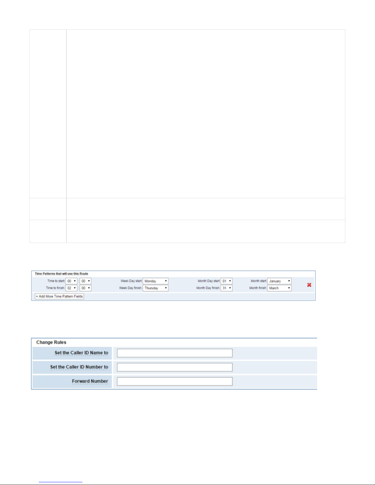
You can create various time routes and use these time conditions to limit some specific calls.
Figure 5-1-4Time Patterns that will use this Route
If you configure like this, then from January to March, from the first day to the last day of these months, from Monday to Thursday, from 00:00 to
02:00, during this time (meet all above time conditions), all calls will follow this route. And the time will synchronize with your Sever time.
Figure 5-1-5Change Rules
You can set your caller ID name and caller number as you like before sending the call to the endpoint. You can also configure forward number
when you have a transfer call.
Page 34

Figure 5-1-6 Failover Call Through Number
You can add one or more “Failover Call Through Numbers”.
Groups
Sometimes you want to make a call through one port, but you don’t know if it is available, so you have to check which port is free. That would be
troublesome. But with our product, you don’t need to worry about it. You can combine many Ports or SIP to groups. Then if you want to make a
call, it will find available port automatically.
Figure 5-2-1 Establish Group
6. Network
On “Network” page, there are three sub-pages, “WAN Settings”, “DDNS Settings”, and “Toolkit”.
WAN/LAN Settings
There are two types of WAN port IP, Static and DHCP. Static is the default type, and it is 172.16.100.1. The LAN port is a fixed IP and it is
192.168.100.1.
Page 35
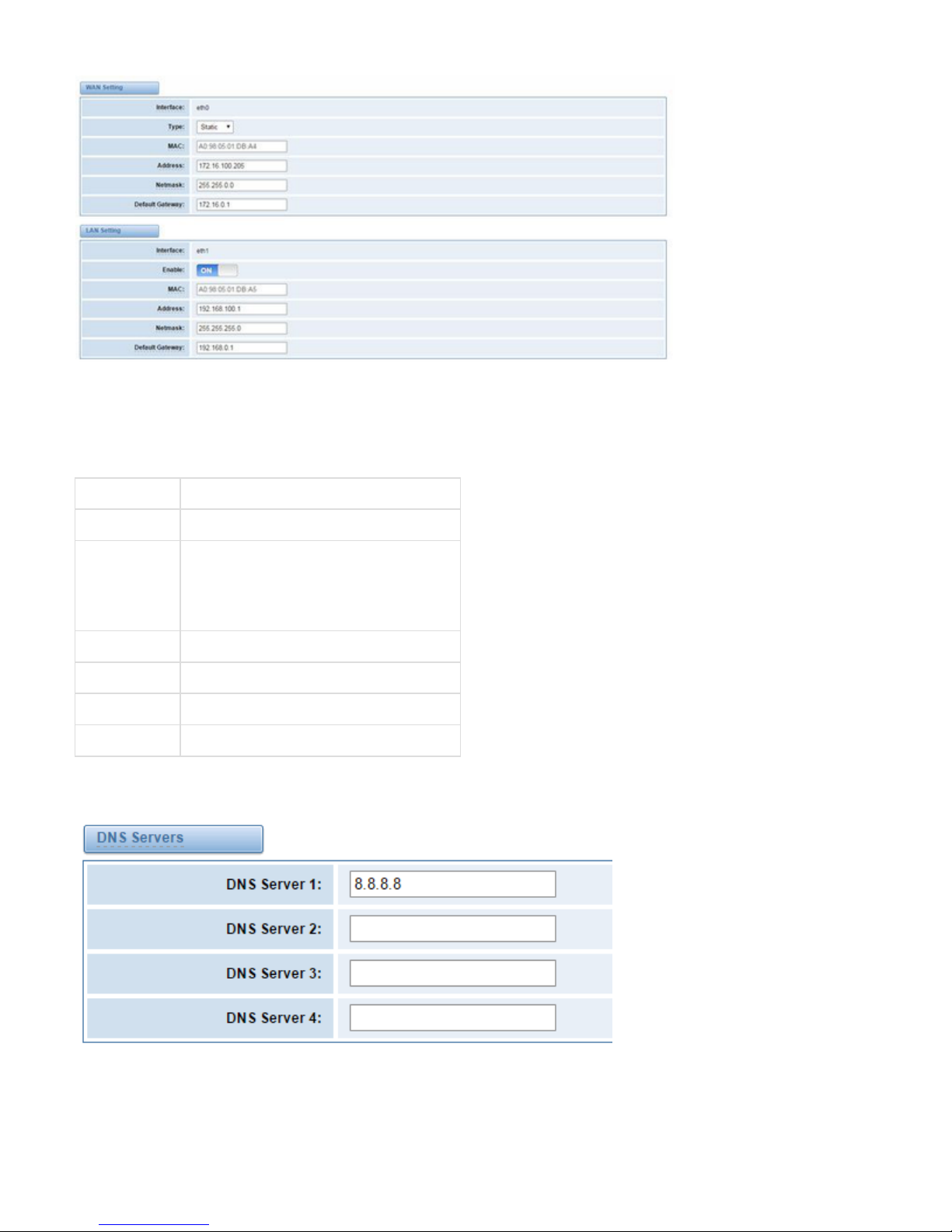
Figure 6-1-1 WAN/LAN Settings Interface
Table 6-1-1Definition of WAN/LAN Settings
Options Definition
Interface The name of network interface.
Type The method to get IP.
Static: manually set up your gateway IP.
DHCP: automatically get IP from your local LAN.
MAC Physical address of your network interface.
Address The IP address of your gateway.
Network The subnet mask of your gateway.
Default Gateway Default getaway IP address.
Basically this info is from your local network service provider, and you can fill in four DNS servers.
Figure 6-1-2 DNS Interface
DNS Servers: A list of DNS IP address. Basically this info is from your local network service provider.
Page 36

DDNS Settings
You can enable or disable DDNS (dynamic domain name server).
Figure 6-2-1 DDNS Interface
Table 6-2-1 Definition of DDNS Settings
Options Definition
DDNS Enable/Disable DDNS(dynamic domain name server)
Type Set the type of DDNS server.
Username Your DDNS account’s login name.
Password Your DDNS account’s password.
Your domain The domain to which your web server will belong.
Toolkit
It is used to check network connectivity. Support Ping command on web GUI.
Page 37
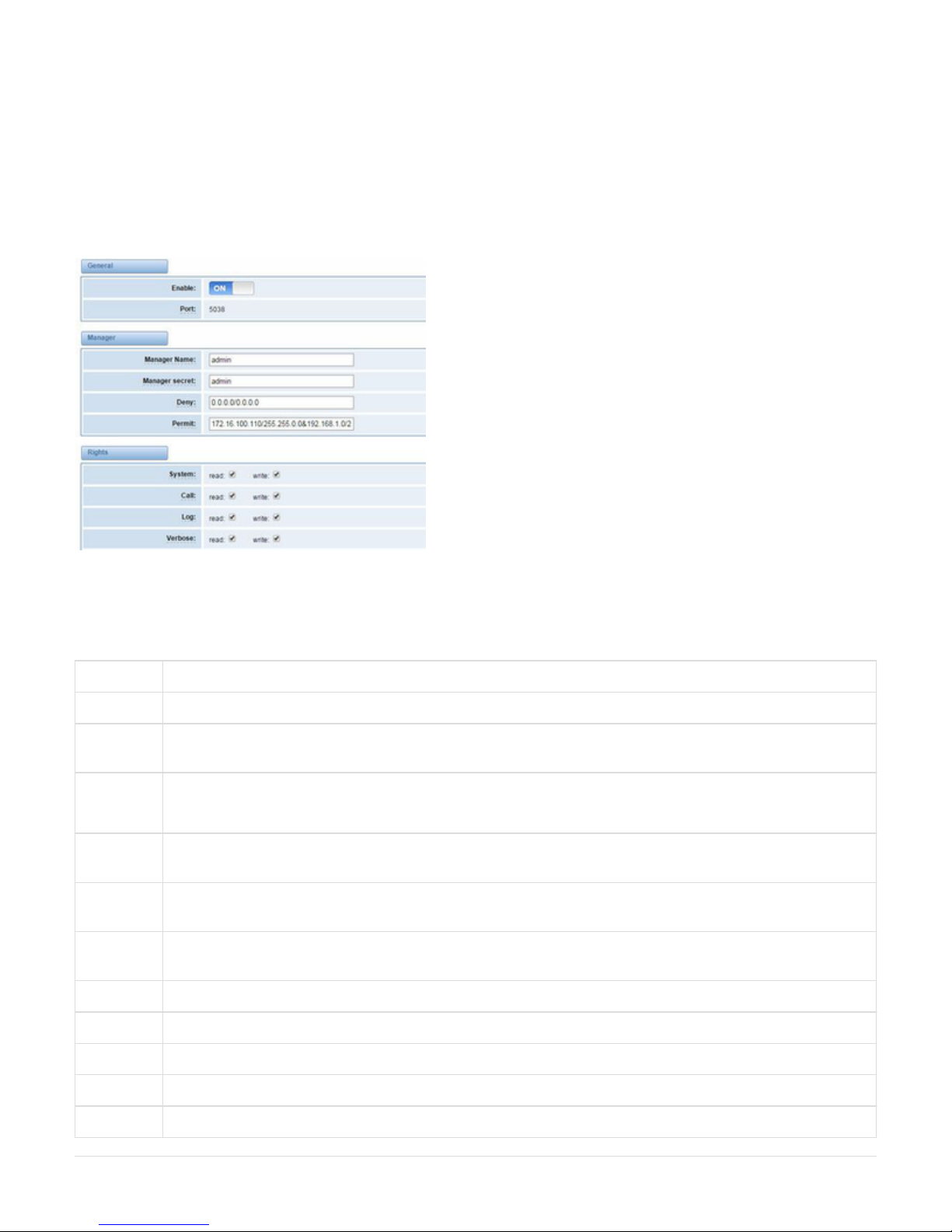
Figure 6-3-1 Network Connectivity Checking
7. Advanced
Asterisk API
When you make “Enable” switch to “ON”, this page is available.
Figure 7-1-1 API Interface
Table 7-1-1 Definition of Asterisk API
Options Definition
Port Network port number
Manager
Name
Name of the manager without space
Manager
secret
Password for the manager.
Characters: Allowed characters “-_+.<>&0-9a-zA-Z”. Length:4-32 characters.
Deny If you want to deny many hosts or networks, use char & as separator. Example: 0.0.0.0/0.0.0.0 or
192.168.1.0/255.255.255.0&10.0.0.0/255.0.0.0
Permit If you want to permit many hosts or network, use char & as separator. Example: 0.0.0.0/0.0.0.0 or
192.168.1.0/255.255.255.0&10.0.0.0/255.0.0.0
System General information about the system and ability to run system management commands, such as Shutdown, Restart, and
Reload.
Call Information about channels and ability to set information in a running channel.
Log Logging information. Read-only. (Defined but not yet used.)
Verbose Verbose information. Read-only. (Defined but not yet used.)
Command Permission to run CLI commands. Write-only.
Agent Information about queues and agents and ability to add queue members to a queue.
Page 38
User Permission to send and receive UserEvent.
Config Ability to read and write configuration files.
DTMF Receive DTMF events. Read-only.
Reporting Ability to get information about the system.
Dialplan Receive NewExten and Var Set events. Read-only.
Originate Permission to originate new calls. Write-only.
All Select all or deselect all.
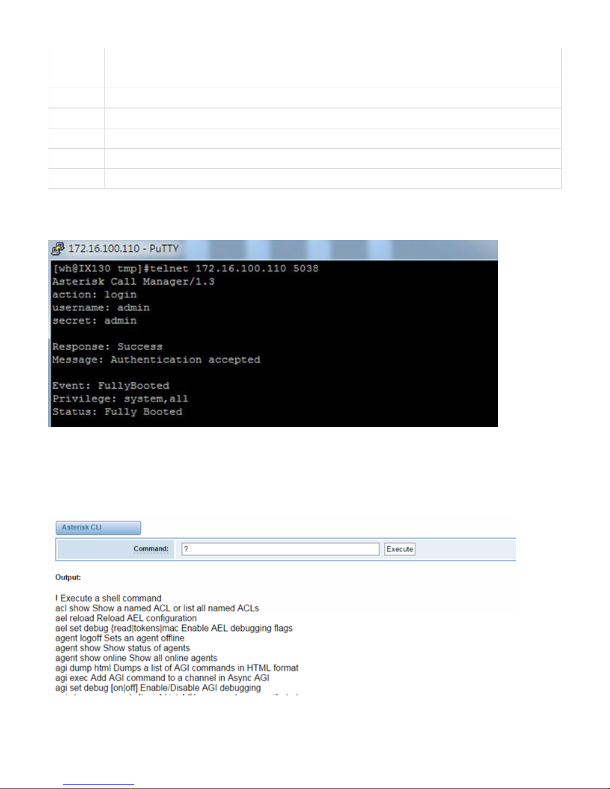
Once you set like the above figure, the host 172.16.100.110/255.255.0.0 is allowed to access the gateway API. Please refer to the following figure
to access the gateway API by putty. 172.16.100.110 is the gateway’s IP, and 5038 is its API port.
Figure 7-1-2 Putty Access
Asterisk CLI
In this page, you are allowed to run Asterisk commands.
Figure 7-2-1 Asterisk Command Interface
Page 39

Table 7-2-1 Definition of Asterisk CLI
Options Definition
Command Type your Asterisk CLI commands here to check or debug your gateway.
If you type “help” or “?” and execute it, the page will show you the executable commands.
Asterisk File Editor
On this page, you are allowed to edit and create configuration files.
Click the file to edit.
Figure 7-3-1 Configuration Files List
Click “New Configuration File” to create a new configuration file. After editing or creating, please reload Asterisk.
Auto Provisioning
Auto provisioning or auto-configuration is an easy, flexible and time-saving way to upgrade firmware and configurations for E1 gateways in mass
deployment. With auto provisioning, all user information can be entered via the central ACS (Auto Configuration Server). ACS can be DHCP
server or TFTP, HTTP and FTP server. It will not take effects immediately but in the next time system is power on. It could be postponed the
execution of restart system also.
Note that system will not be upgrade the firmware and update configurations if the connection between ACS and gateway is disconnect.
Preparation
The following should be prepared before anto provisioning being applied.
Page 40

l Enable the auto provisioning in gateway
l The ACS has been prepared
l The network between gateway and ACS is connected
Configuring gateway
Usually, the feature is disabled before being on sale. To activate the auto provisioning function, please follow the procedures as below.
Step 1 On the -> ADVANCED Auto Provision interface
Step 2 Enable the ‘Enabled’ option and select ACS. DHCP option 66 can be enabled if ACS has been work as DHCP server, otherwise please
select protocol of provisioning and fill the value of ‘ ’. Username and password may need to be filled in FTP/HTTP for theAuto Config Server URL
purpose of system safety. Do not forget to select Firmware upgrade, upgrade mode and fill the value of timeout, and click ‘ .Save’
Step 3 Set interval of checking in -> then enable it, and click ‘ .LOGS System notice Save’
Table 7-4-1 Definition of Auto Provision
Options Definition
Enabled Whether to enable or disable Auto Provision
DHCP Option 66 Get ACS server address from Option 66 via DHCP
Protocol Set protocol of connection
Auto Config Server
URL
The config server domain or IP address
User Name The account of downloading from ACS
Password The password of downloading from ACS
Timeout The max limit time for downloading firmware
Firmware Upgrade Enable/disable the mode of downloading firmware
Upgrade Mode Select upgrade time.
Power: start upgrade configuration when Power on. Power + Period: Set the frequency of checking the latest
configuration when gateway running
Table 7-4-2 Definition of system notice
Options Definition
Enable Whether to enable or disable system notice
Check Interval When Upgrade Mode is set, this parameter specifies the interval of Checking.
Page 41
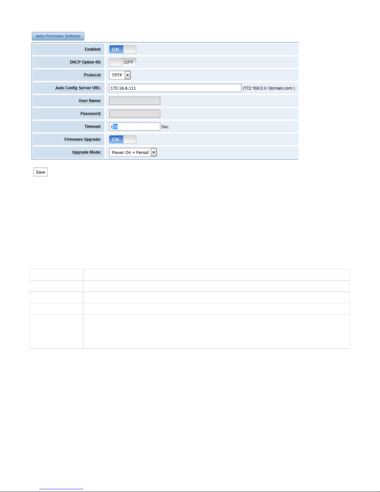
Figure 7-4-1 Auto Provision interface
Configuring ACS
The Auto Configuration Server can be the one of TFTP, FTP and HTTP server. The ACS is used to store the firmware release and configurations
files of the devices under management.
List the primary files in ACS download directory as table 7-4-3:
Table 7-4-3 Definition of ACS files
Options Definition
DGW100x-current.bin The firmware image
common.conf The wildcard configuration file for the whole gateway
defconfig.tar.gz The default(factory) configuration file
EPC-{mac}.conf The private configuration file for the specified gateway.
Naming rules: “EPC-“ + “mac” +”.conf”. The naming prefix of “EPC-” stands for the private configuration file, “mac” is
the physical address of network interface card but removed semicolon and “.conf” is the suffix. For example, the
EPC-a0980501dbca.conf, ‘a0980501dbca’ is the MAC address (A0:98:05:01:DB:CA).
The format of common.conf , EPC-{mac}.conf and defconfig.tar.gz:
(1). Common.conf
[firmware]
FW_NAME=DGW100x-current.bin //Firmware image name
FW_MD5=b3603f3c3b5e7eb6326498640f151c79 //The md5 of firmware image
FW_VERSION=1.1.2 //Firmware version
[configs]
CONFIG_NAME=defconfig.tar.gz // default configuration file(compressed)
Page 42

CONFIG_MD5KEY=2cd2dfbe52482405350816e3698cb530 // the md5 of default configuration file
(2).EPC-{mac}.conf
[dns]
DNS_SERVER1=8.8.8.8
DNS_SERVER2=8.8.4.4
DNS_SERVER3=
DNS_SERVER4=
[ntp]
NTP_SERVER1= 0.cn.pool.ntp.org
NTP_SERVER2= time.nist.gov
NTP_SERVER3= time.windows.com
[eth0]
ENABLE=yes
TYPE=static
DHCP=no
IPADDRESS=172.16.100.223
NETMASK=255.255.0.0
GATEWAY=172.16.0.1
[eth1]
ENABLE=yes
TYPE=static
DHCP=no
IPADDRESS=192.168.100.223
NETMASK=255.255.0.0
GATEWAY=192.168.0.1
[web_login]
username=admin
password=admin
(3). Defconfig.tar.gz
Figure 7-4-2 the overview of defconfig.tar.gz
Page 43

1.
1.
1.
Provisioning example
After auto provisioning is enabled, the gateway will visit the Auto Configuration Server and download the updated files periodically based on the
timer ( -> ). By default, the timer is set as every hour. System will receive a message from ACS, like figure Check Interval LOGS System notice
7-4-3, and the message will be display in the system notice ( -> ).LOGS System Notice
Auto provisioning will not take effects immediately but in the next time system is power on. It could be postponed the execution of restart system
also.
Now, an example of using Auto Provisioning will be given in the following.
Activate the auto provision (TFTP) in -> like figure 7-4-4.ADVANCED Auto Provision
Figure 7-4-4 Auto provision settings
Enable the check interval in -> -> like figure 7-4-5.LOGS Log settings System Notice
Figure 7-4-5 Check interval setting
Configuring the ACS(Generate the md5 of firmware and defconfig.tar.gz)
l Copy the firmware, defconfig.tar.gz, common.conf and EPC-{mac}.conf to the working directory of TFTP server.
Page 44

Figure 7-4-6 The working directory of TFTP server
Notice:
The demo of E1 gateway mac address is A0:98:05:01:DB:CA (eth0), therefore the private configuration file is EPC-a0980501dbca.conf.
l Generate the md5 of firmware and defconfig.tar.gz. Then fill in common.conf and EPC-{mac}.config.
Figure 7-4-7 Generate the md5 of firmware and configuration
Figure 7-4-8 Common.conf
Page 45

Figure 7-4-7 EPC- a0980501dbca.conf
l Start TFTP service. Tftpd32.exe is a useful TFTP tools in windows7, then make sure TFTP server is select.
Page 46

1.
Figure 7-4-8 Demo TFTP server
The system will receive an auto provision message in web GUI.
Figure 7-4-9 System notice logs
Figure 7-4-10 Auto provision upgrade notification
2.Restart the system. It will take about 3 minutes almost to download, upgrade Firmware and update configurations.
Figure 7-4-11Downloading the firmware and configs
Figure 7-4-12Applying the firmware and configs
SNMP
Simple Network Management Protocol (SNMP) is an application–layer protocol, which is used to manage and monitor network elements and
exchange management information between network devices. By default SNMP uses port 161 for communication.
Since the inception SNMP, it embraces three versions: v1, v2c and v3. V1 and v2c are the most implemented version of SNMP; v3 is target at the
high security when compare to its older versions. The gateway support private SNMP MIBs (private enterprise number) to access.
Parameters in SNMP setting
Page 47

Table 7-5-1Definition of SNMP setting
Options Definition
SNMP Enable Whether to enable SNMP
System Contact System contact information(optional)
System Location The locale of system contact(optional)
Private Enterprise
Number
The number is used for defining private SNMP MIBs which is assigned by Internet Assigned Numbers Authority (IANA).
For more information, please access:
http://pen.iana.org/pen/PenApplication.page
SNMP Version Select version of SNMP
Community
Configuration
Define a community name to security name
Group
Configuration
Define the security name to a group
View Configuration Set a view to let the group have rights to do
Access
Configuration
Grant the group can access to the view(read/write/notify)
User Configuration Only exist in v3. Add a v3 account to SNMP. Notice that the length of auth password and privacy password are more
than 8.
Activating SNMP
Usually, the feature is disabled by default. To activate the SNMP feature, please follow the Figure 7-5-1.
The Interface is in the -> . System contact, location and private enterprise number are optional. Figure 7-5-1 is the SNMPADVANCED SNMP
setting interface.
Page 48

Figure 7-5-1 Activating the SNMP
Note: Do not forget to click ‘ ’ to take effect. After configuration, The SNMP feature is activated immediately.Save
Verify SNMP
A powerful, indispensable and easy-to-use MIB browser is convenient for engineer/manager to manage SNMP enabled network devices and
applications. In this session, Manage Engine MIB browser is selected. It allows user to issue SNMP requests to retrieve agent's data, or make
changes to the agent. It is free tool for Windows, Mac and Linux.
(1). Get SNMP parameters via SNMP MIB browser. It’s supposed that Manage Engine MIB browser is installed perfectly. Figure 7-5-2 is the main
interface of Manage Engine MIB browser.
Figure 7-5-2 Manage Engine MIB browser
And the field of , and are filled with , and respectively. Object ID is the node of SNMP MIBs,Host Port Community 172.16.100.223 161 public
e.g. “.1.3.6.1.2.1.1.6.0” is system location and “.1.3.6.1.2.1.1.1.0” is system description.
Page 49

Figure 7-5-3 Get system location
After the rest field has been filled, then verify it. Click -> to get the value of system location and it returns the value which weOperations GET
just set.
(2). Set SNMP parameters via SNMP MIB browser. For example, set the system name. system name is “dgw100x” by default, then set it as “VoIP
gateway”. See figure 7-5-4.
Click -> to attain the current system name.Operations GET
Fill the field of with “VoIP gateway”.Set Value
Click -> to set the system name.Operations SET
Click -> to attain the modified system name.Operations GET
Page 50
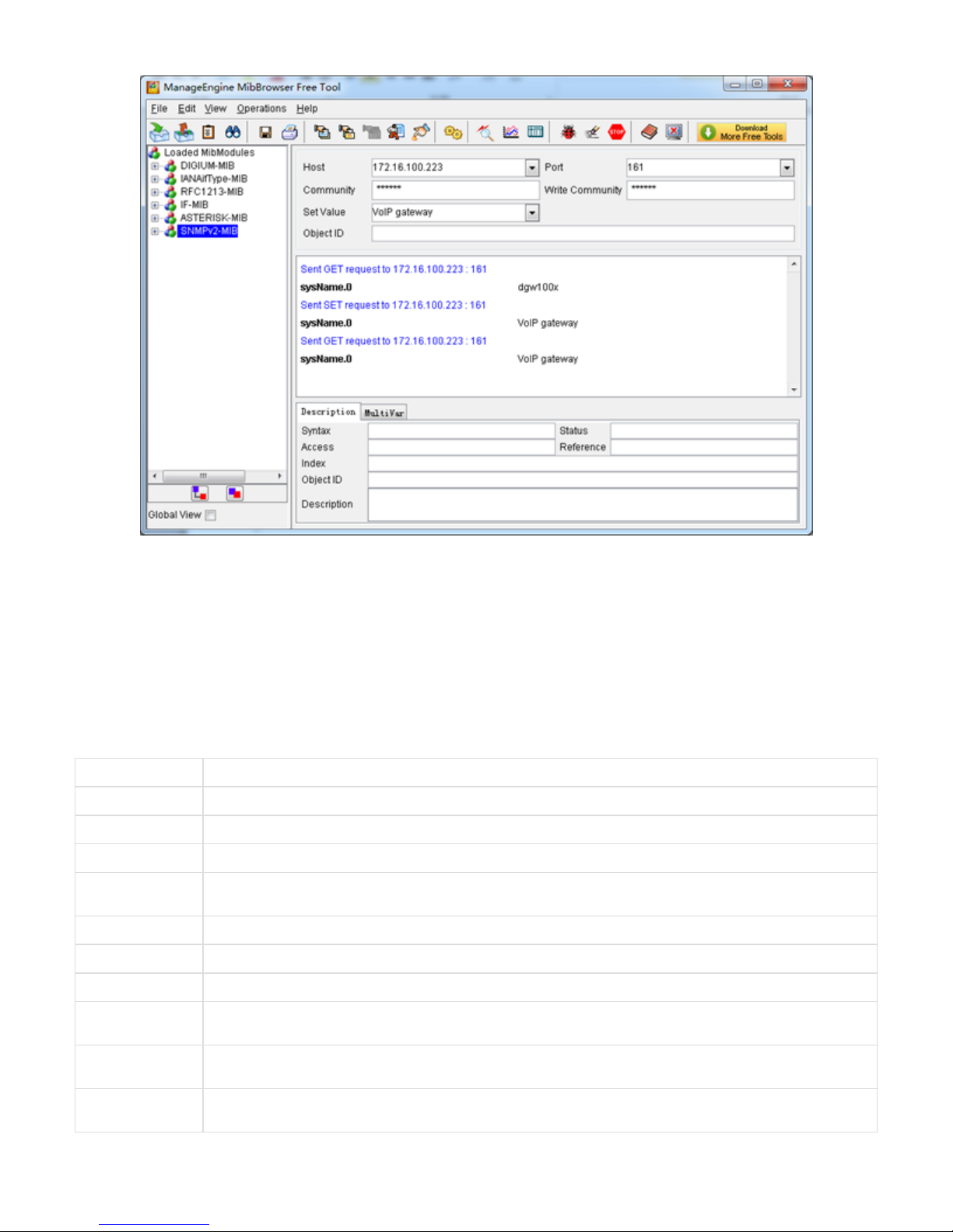
Figure 7-5-4 Set system name
TR069
TR069 is a remote management solution which offers a single interface to manage the ACS and automate the deployment and support of data,
voice and video services, thereby reducing operation and support costs, while enhancing customer satisfaction. Its user-friendly interface covers
the entire service lifecycle, from centralized remote provisioning of services, to inventory management, group updates, monitoring, event
triggering, and support automation. Figure 7-6-1 is TR-069 configuration interface and table 7-6-1 is its definition.
Table 7-6-1 Definition of TR069 configuration interface
Options Definition
Acs Url Specify the URL of the ACS
Acs Username Specify the user name to be used by the device to authenticate with the ACS.
Acs Password Specify the password to be used by the device to authenticate with the file server
Provisioning Code Information of the device vendor, which may be used to indicate the primary service provider and other provisioning
information to the ACS. It can be numbers or English letters.
Model Name A brief description of the interface type or name. It is a string of characters.
Periodic Enable Used to specify whether to periodically report to the ACS.
Periodic Interval The interval for reporting to the ACS.
Connection Request
Url
The address used for the ACS to connect back to the device.
Connection Request
Username
The account used for the ACS to connect back to the device, for example, admin.
Connection Request
Password
The password used for the network management server to connect back to the device.
Page 51
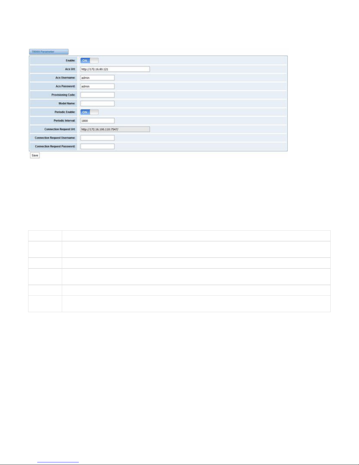
Figure 7-6-1 TR069 configuration interface
Network Capture
The gateway have been supplied a network packets capture in the web for ease of user to analysis, capture and monitor the gateway’s network
status, RTP flows, protocol analysis and so on.
Table 7-7-1 Definition of Network capture
Options Definition
Network
Interface
Specify which interface to be capture packets from. ‘All’ means capture packets from all interfaces
Source host Specify which source host IP address to listen for
Destination
host
Specify which destination host IP address to listen for
Port To specify a port that is either source or destination direction
Protocol To specify which protocol to be captured, ‘All’ stands for capture multi-protocols, the SIP default port is 5060, If you are using a
different port, please amend it.
The interface is in -> .ADVANCED Network Capture
Page 52
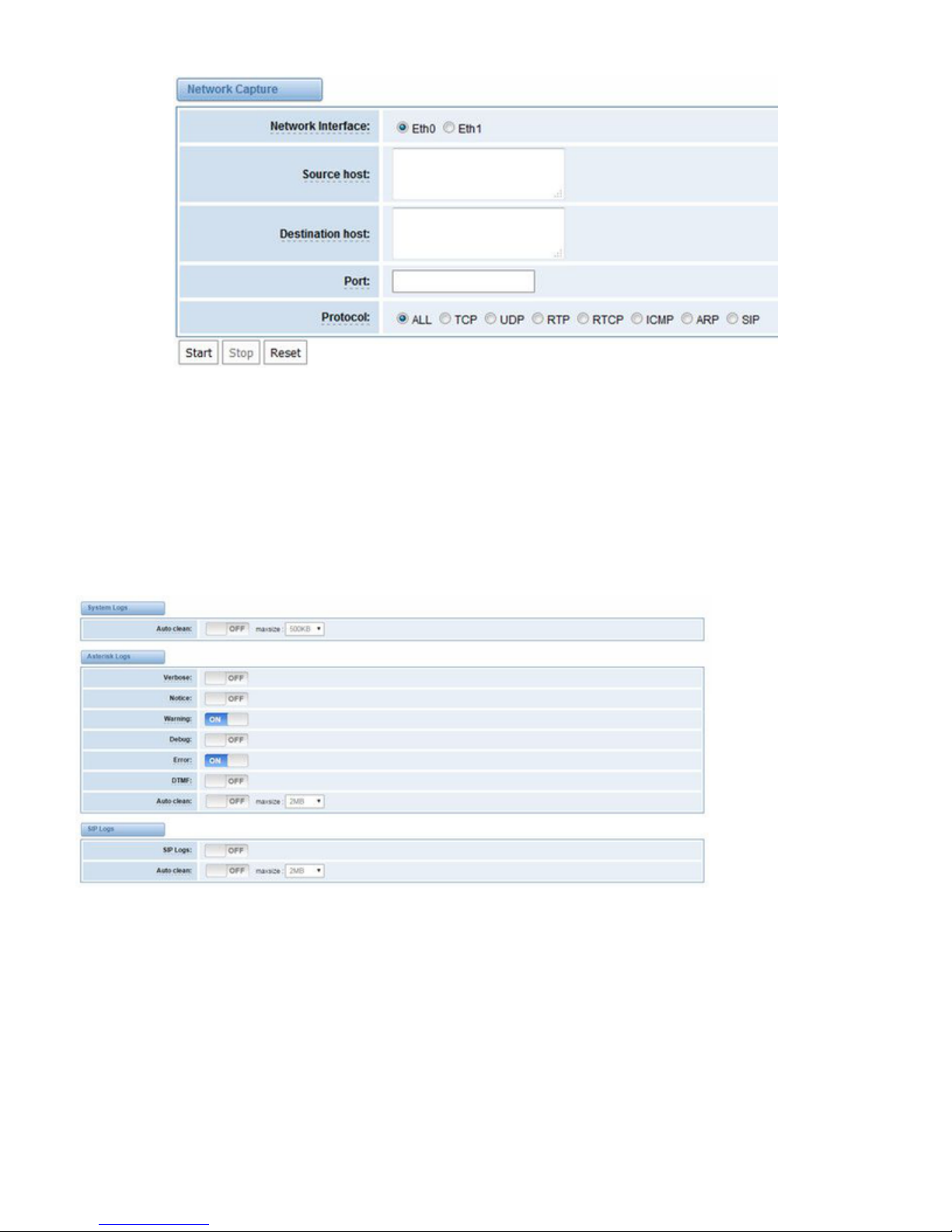
Figure 7-7-1 Network capture interface
8. Logs
On the “ ” page, you should set the related logs on to scan the responding logs page. For example, set “ ” on like theLog Settings SIP Logs
following, then you can turn to “ ” page for sip logs, otherwise, sip logs is unavailable. And the same with other log pages.SIP
Log Settings
Page 53

Figure 8-1-1 Logs Settings
Figure 8-1-2 System Logs Output
Table 8-1-1 Definition of Logs
Options Definition
Auto
clean:
(System
Logs)
switch on : when the size of log file reaches the max size,
the system will cut a half of the file. New logs will be retained.
switch off : logs will remain, and the file size will increase gradually.
default on, default size=1MB
Verbose: Asterisk console verbose message switch.
Notice: Asterisk console notice message switch.
Warning: Asterisk console warning message switch.
Debug: Asterisk console debug message switch.
Error: Asterisk console error message switch.
DTMF: Asterisk console DTMF info switch.
Page 54

Auto
clean:
(asterisk
logs)
switch on : when the size of log file reaches the max size,
the system will cut a half of the file. New logs will be retained.
Switch off: logs will remain, and the file size will increase gradually.
default on, default size=2MB
SIP Logs: Whether enable or disable SIP log.
Auto
clean:
(SIP logs)
switch on : when the size of log file reaches the max size,
the system will cut a half of the file. New logs will be retained.
Switch off: logs will remain, and the file size will increase gradually.
default on, default size=2MB
IAX2 Logs Whether enable or disable IAX log
Auto
clean
switch on : when the size of log file reaches the max size,
the system will cut a half of the file. New logs will be retained.
Switch off: logs will remain, and the file size will increase gradually.
default on, default size=2MB
MFC/ R2
Logs
Whether enable or disable MFC/ R2 Logs log.
Auto
clean
switch on : when the size of log file reaches the max size,
the system will cut a half of the file. New logs will be retained.
Switch off: logs will remain, and the file size will increase gradually.
default on, default size=2MB
PRI Logs PRI port logs. You can choose one or more ports. If you choose "All", the "PRI" page will show you the logs about all the ports.
Auto
clean (PRI
logs)
switch on : when the size of log file reaches the max size,
the system will cut a half of the file. New logs will be retained.
Switch off: logs will remain, and the file size will increase gradually.
default on,default size= On the “ ” page, you should set the related logs on to scan the responding logs page. ForLog Settings
example, set “ ” on like the following, then you can turn to “ ” page for sip logs, otherwise, sip logs is unavailable. AndSIP Logs SIP
the same with other log pages.
.SS7 Logs Whether enable or disable SS7 log
Auto
clean
switch on : when the size of log file reaches the max size,
the system will cut a half of the file. New logs will be retained.
Switch off: logs will remain, and the file size will increase gradually.
default on, default size= B2M
Call
Statistics
Whether enable or disable Call Statistics.
Page 55
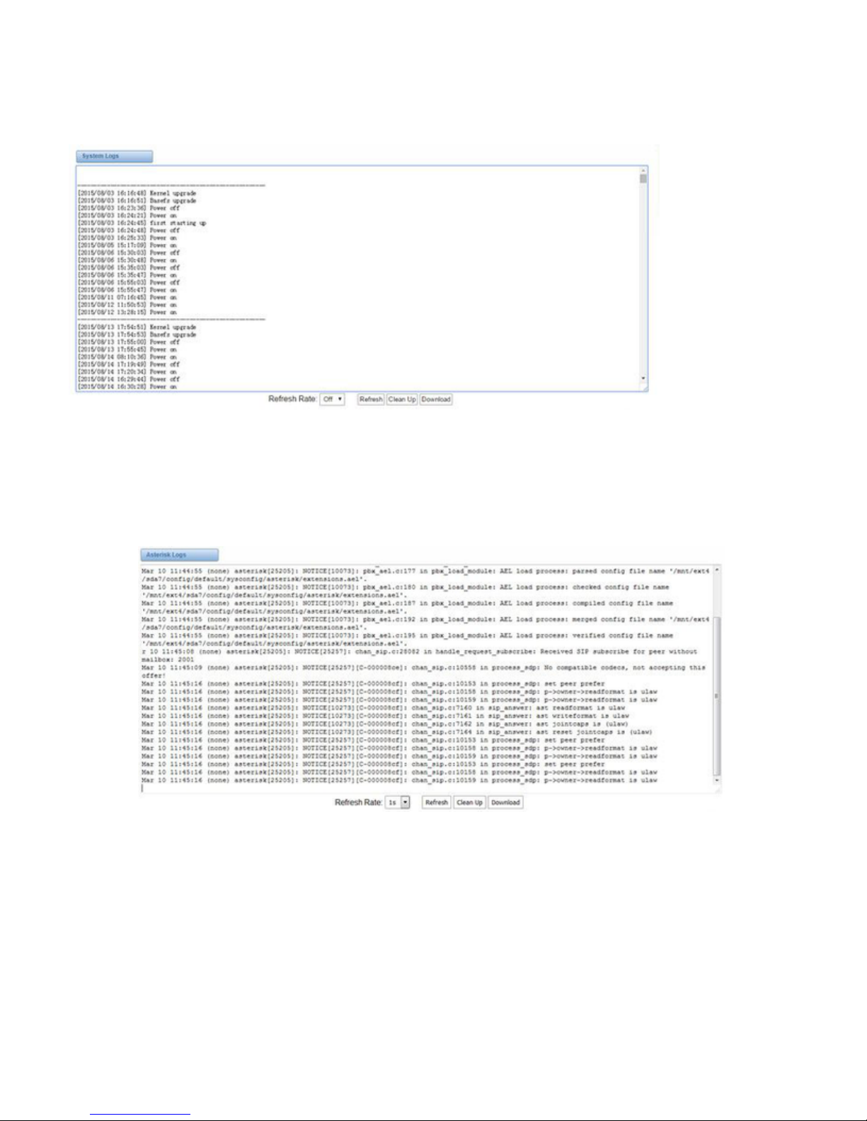
System log
System log record every time power on, power off and firmware upgrade information.
Figure 8-2-1 System Log
Asterisk logs
On the pages of “ ”, “ ”, “ ”, “ ”, “ ” and “ ”, there owns the some functions—Displays the log by port, refresh regularlyAsterisk SIP IAX2 SS7 PRI MFC/R2
and log download.
Figure 8-3-1 Asterisk Log
Call Statistics
The figure of call statistics, you’ll find “ ”, “ ”, “ ”, “ ”, “ ”, “ ”, “ ”, “Answered congestion Call busy Call failed No answer Current calls accumulated calls
” and “ ”. “ ” stands for Answer Seizure Ratio. “ ” will count the whole calls in the gateway. The call statisticsCalls duration ASR ASR Calls duration
will be saved before power off. It will be loaded after power on. It can be refreshed by itself. You can reset the statistics manually.
Page 56

Figure 8-4-1 Call Statistics
Note: Do not forget to enable call statistics in “ ” if you want to statistics the calls.Log Setting
System Notice
The system notice could be generated by system to inform the network manager of what is going on if it has been enabled. Firmware upgrade
messages from official website and auto provisioning messages from ACS are main notice right now. And at first, enable the system notice
function like figure 8-5-1.
Figure 8-5-1 enable system notice function
After about an hour, a system message is received in the web like 8-5-2.
Figure 8-5-2 enable system notice function
Note: Do not forget to enable system notice and check interval in “ ” if you want to receive system messages.Log Setting
 Loading...