

Opentech ODT 4200PVR User Manual
User’s
Manual
Personal Video Recorder
Free To Air Digital Terrestrial Receiver
ODT 4200PVR
OPENTECH INC.
6F, Dongwon Bldg., 275 Yangjae-Dong,
Seocho-Gu, Seoul, Korea 137-130
Tel : +82 2 589 4776
Fax : +82 2 589 4798
E-mail : sjyeo@opentech.co.kr
OPENTECH MIDDLE EAST
RA 08 ZE07, Jebel Ali FZ,
P.O BOX 18033, Dubai, UAE
Tel : +971 4 8838375
Fax : +971 4 8838376
E-mail : opentech@emirates.net.ae
OPENTECH Multimedia GmbH
Industriestr. 1 a
65760 Eschborn, Germany
Tel : + 49 (0) 6196 90 200
Fax : + 49 (0) 6196 90 2019 / 2029
E-mail : simon@open-tech.net
Open The Next Digital
Digital Terrestrial Receiver
120 / REV. 002

1. SAFETY PRECAUTIONS
2. GENERAL FEATURES
3. HOW TO CONNECT YOUR RECEIVER
4. HARDWARE DESCRIPTION
5. MENU OPERATION
6. HOW TO DO RECORD & PLAYBACK
7. HOW TO DO RESERVATION RECORD
8. TROUBLE SHOOTING
9. TECHNICAL SPECIFICATIONS
10. DIGITAL CHANNEL INFO
3
4
5
7
11
24
27
29
30
32
Table of Contents
Highest Tuning Speed!
Quick Channel Change!
Easy Installation & Operation
Table of Contents

GENERAL FEATURES
4
SAFETY PRECAUTIONS
3
This receiver has been manufactured to satisfy the international
safety standards.
Please read the following recommended safety precautions carefully
MAINS SUPPLY : 95�240V AC 50/60Hz
LOCATION : Locate the receiver indoor.
Locate receiver away from potential hazards such as houseplants, lighting, raining and direct sunlight.
OVERLOADING : Do not overload wall outlets, extension cords or adapters as this
can result in fire or electrical shock.
LIQUIDS : Keep liquids away from the receiver.
CLEANING : Before cleaning, disconnect the receiver from the wall socket.
Use a cloth lightly dampened with water (no solvents) to clean the exterior.
VENTILATION : Do not block the receiver ventilation holes. Ensure that free airflow is
maintained around the receiver.
Never set the receiver on soft furnishings or carpets. Do not use or store the receiver
where it is exposed to direct sunlight, or near heater.
Never stack other electronic equipment on top of the receiver.
Place the receiver at least 30mm from the wall.
ATTACHMENTS : Do not use any attachment that is not recommended by the manufacturer,
as it may cause a hazard or damage the equipment.
SERVICING : Do not attempt to service this product yourself. Any attempt to do so will
make the warranty invalid.Refer all servicing to a qualified service agent.
LIGHTNING : If the receiver is installed in an area subject to intense lighting activity,
protection devices for the receiver mains connector and modem telephone line are essential.
The individual manufacturer’s instruction for safeguarding other equipment, such as TV set,
Hi-Fi, etc., connected to the receiver, must also be followed during lighting storms.
- Fully MPEG-2 & DVB-T Compliant
- Input Frequency 174 ~ 862 MHz
- 2 Input Tuner with Loop Through IF Signal
- Supports DVB-T modulation schemes : QPSK, 16-QAM and 64-QAM
- Implements non-hierarchical and hierarchical 2K and 8K system operation
- Fast Booting & Auto Scan
- Quick Channel Changing Speed Less than 2Sec
- Max. 2000 Channels (TV & Radio) Programmable
- User Friendly 256 Colors OSD & Easy GUI
- A lot of OSD Language supported
- Supports EPG, PIG
- Radio Channel Background Display
- Favorite Channel List Programmable
- Master PIN Code Function & Parental Lock Function
- 20 Steps Volume Control
- Automatic NTSC / PAL Detection and Simple Video Converter (NTSC
PAL)
- Window based S/W Download Program Supported by RS232 Serial Port
- Set to Set Download (Main Program, Channel Data)
- 4:3, 16:9 Letter Box & Teletext using OSD
- 7 Segment-4 Digit Display
- 5 Buttons on the Front Panel (Power On/Off, Channel Up/Down, Volume Up/Down)
- 2 SCART Output for TV & VCR
- 3 RCA Output for Video, Audio L/R
- Wide PLL RF Modulator (PAL B/G, I, D/K)
- S/PDIF Digital Audio
- Recording Capacity
- 40hours for 3.5Mbps Stream with 80GB HDD
- Time Shift Function With a Live Channel
- Fast Forward / Revers in Replaying
- 2Tuners : One Channel Watching + One Channel Recording
- Book Marking Function
- Delayed Recording in EPG
1. SAFETY PRECAUTIONS 2. GENERAL FEATURES
HOW TO CONNECT YOUR RECEIVER
6
HOW TO CONNECT YOUR RECEIVER
5
1) LOCATION OF THE RECEIVER
Your receiver should be placed under proper ventilation.
Don't put in completely enclosed cabinet that will restrict the flow of air, Resulting overheating.
The location should be safeguarded from direct sunlight, excess moisture, rough handling or
household pets
Avoid stacking other electronic components on the top of the receiver.
The location should be safely accessible by the cable from your antenna system.
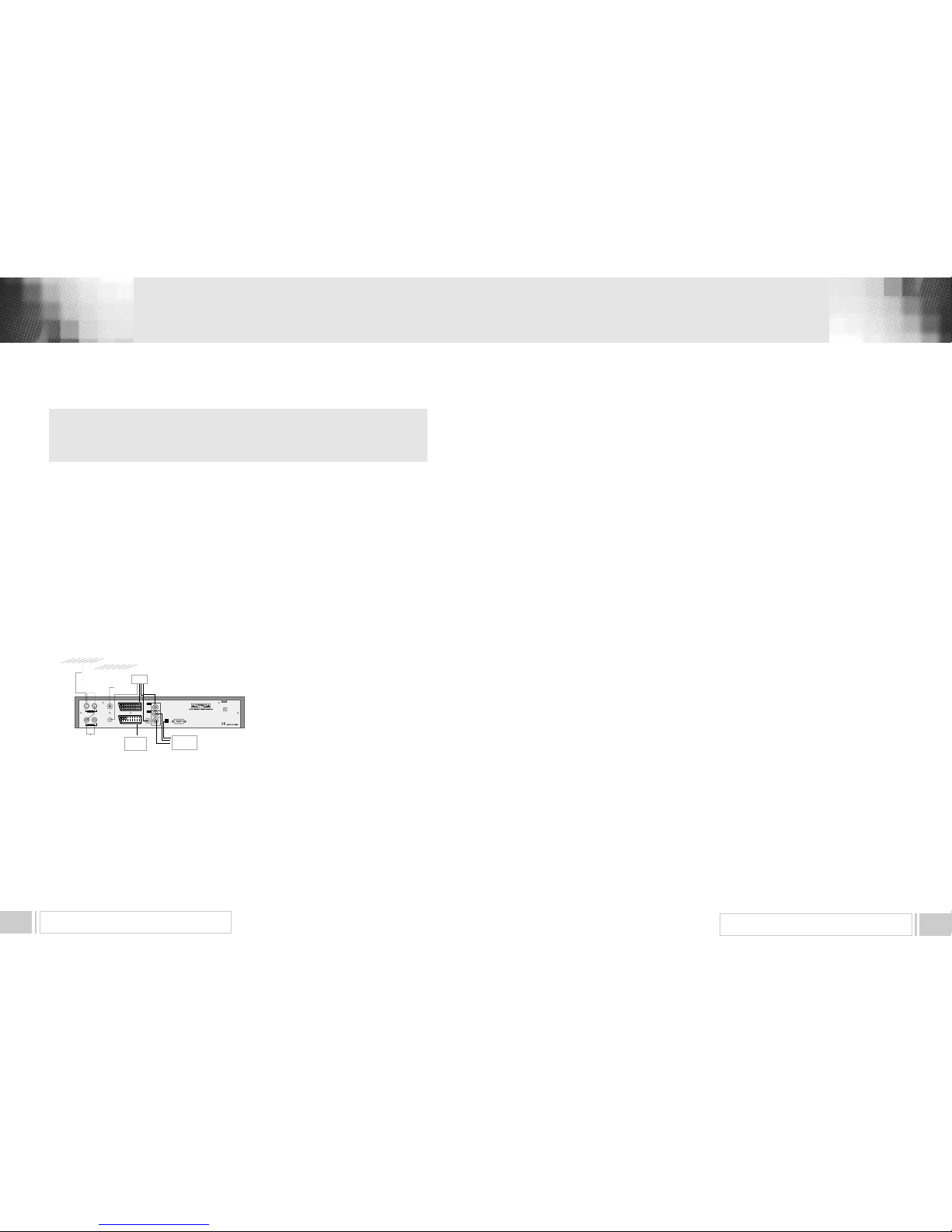
2) CONNECTING THE RECEIVER WITH ANTENNA
Connect the coaxial cable to "ANTENNA.(A/B)" terminal marked at the rear of the receiver. All cable
connectors should be finger tightened, do not use any kind of wrench on the cable over connectors.
The cable should be 75‰ impedance coaxial twisted at the end with a ‘IEC’ type connector.
< Loop through >
In Automatic Channel Search Menu please set
connection type into Loop through if a link from
tuner A to B is made with a coaxial cable. This
mode will use all settings for tuner A also for
tuner B. Tuner A will be used for watching and
tuner B for recording onlySeparated.In
Automatic Channel Search Menu please set
connection type into Loop through if a link from
tuner A to B is made with a coaxial cable. This
mode will use all settings for tuner A also for tuner B. Tuner A will be used for watching and tuner B
for recording only
3. HOW TO CONNECT YOUR RECEIVER
Please DO NOT plug in the main power supply cord until you have
finished all the connections.
3) CONNECTING THE RECEIVER TO TV
To connect the receiver with your television, you can follow three methods :
through RF cable, and through SCART cable, S-Video Cable.
Connect the RF cable to the terminal marked "TV OUT" at the rear panel of the receiver and its other
end to the TV RF input socket.
In the case of connecting your TV through SCART cable, connect the SCART connector marked TV
to respective SCART port in the TV.
Connect the S-Video cable to the terminal marked ‘S-VIDEO’ at the rear panel of the receiver and its
other end to the TV or VCR S-VIDEO input socket.
4) CONNECTING YOUR VCR
To connect a VCR, the receiver has been provided with SCART at the rear marked ‘VCR'. Using a
SCART
connector, the VCR can be connected to the receiver.
5) CONNECTING EXTERNAL AUDIO HI-FI SYSTEM
To connect any external Audio Hi-Fi system, the receiver has been provided with two RCA
connectors at the back of the receiver, marked with Audio L and R respectively to connect the left and
Right Audio.
6) CONNECTING YOUR ANALOG RECEIVER
To facilitate the user using analog receiver to view analog channels, the receiver has been provided
with a loop through terminal marked as "IF OUT".
Connect the coaxial cable from this terminal to the IF input terminal of your analog receiver. Now by
keeping the receiver in standby, you will be able to tune and view analog channels
from your analog receiver.
ANT IN
TV
VCR
S/PDIFS-VIDEO SERIAL PORT
R
L
TV OUT
ANTENNA
ANTENNA
(A/B)
ANTENNA
(A/B)
TV
ANTENNATVANTENNA
Loop Out
(A/B)
Loop Out
(A/B)
LOOP OUT
AC 100V-240V~
50Hz/60Hz
MAX.35W
VIDEO
AUDIO
TV
VCR
Hi-Fi
Stereo Audio
HARDWARE DESCRIPTION 8
HARDWARE DESCRIPTION7
4.A. FRONT PANEL
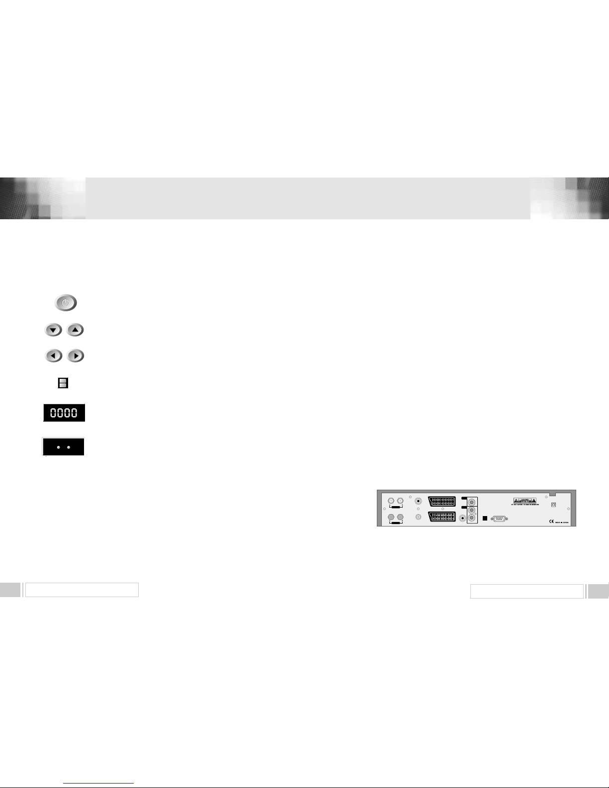
1) ANTENNA (A/B)
: This port is to connect the coaxial cable. The IF input is provided through this port and
the input frequency range is 174 ~ 862Mhz.
2) LOOP OUT (A/B): This is used to connect your digital receiver to your TV set so that you can
still Watch analogue programs. (2,7,9,10 & SBS)
3) SERIAL PORT: This port is used for software upgrades when connected to your computer
through a serial cable.(Not Supplied)
4) TV SCART : This i s u s e d t o c o n n e c t y o u r TV via Scart leads.
5) VCR SCART : This is used to connect your VCR via Scart leads.
(When you connect external sets to above two SCART sockets, always use fully featured SCART
cables)
6) S/PDIF DIGITAL OUTPUT : This is for connecting digital optical audio to devices such as
surround sound amplifiers.
7) VIDEO, AUDIO R/L : These RCA connectors are used to connect the digital receiver to any
external device with RCA inputs. (TV set, Video, Projetor etc)
8) ANT IN : To be looped from TV OUT when connecting the digital receiver via RF to your TV.
9) TV OUT : Used to connect the digital receiver via RF to your TV.
10) POWER INPUT : This cable is to be Plugged into the AC mains power outlet.
The input AC volts range is 90V to 240V, 50Hz/60Hz supply.
11)S-VIDEO : Used to connect the receiver via S-VIDEO to Input such as TV Sets.
4.B. REAR PANEL
4. HARDWARE DESCRIPTION
ANT IN
TV
VCR
S/PDIFS-VIDEO SERIAL PORT
R
L
TV OUT
ANTENNA
LOOP OUT
AC 100V-240V~
50Hz/60Hz
MAX.35W
VIDEO
AUDIO
1) POWER : This key is used to turn the receiver on and off (stand by).
2) CH : These keys are used to change the channels.
3) VOL : These keys are used to increase and decrease the volume
level manually.
4) INFRARED SENSOR : This is to receive the IR commands from the
RCU. Do not block the view of the sensor.
5) 7 SEGMENT DISPLAY : This SEGMENT display will show the current
channel number.While the receiver is in stand by mode, the display will show
the current time.
POWER
C H
VOL
INFRARED SENSOR
7 SEGMENT DISPLAY
6) LED DISPLAY: This LED display will show the current power mode status.
If receiver is in stand by mode,stand by mode LED will be on. and when
receiver is in on mode, on mode LED will be on.
(Option for LED display model only)
LED DISPLAY
STANDBY ON

HARDWARE DESCRIPTION 10
HARDWARE DESCRIPTION9
POWER : This is used to switch the receiver to ON/STANDBY mode.
MUTE : This key is used to toggle between normal and muted audio
0-9 NUMERIC KEYS : These keys are used to enter numeric values and to
select the channel directly by entering its number.
CH
▲▲CH▼▼
: These keys are used to change channels and to browse the
menu.
VOL▶▶VOL◀◀: These keys are used to vary the volume level and to change
the cursor options in the menu.
MENU : This key is used to open up the menu.
EXIT : This key is used to exit from any menus.
OK : This key is used to enter and confirm any data to the receiver in the
menu systems. The Channel list can be accessed directly by pressing this
Key in the normal view mode.
Page Up : This key is used to page up the menu.
Page Down : This key is used to page down the menu.
GUIDE : This key is used to open up the Electronic Program Guide.
i : This key is used to view the channel information.
: This key is used to toggle between the TV channel and the radio channel.
LAST : This key is used to return to the previous channel.
AUDIO : This key is used to select the soundtrack list for the
current service and also used to select audio mode.
WIDE : This is used to change the screen mode , Auto, 16:9, 4:3, Letter Box
L/R : This is used to change the sound mode , LEFT , RIGHT ,STEREO
FAV : This key is used to switch between favorite lists.
TEXT : This key is for Teletext.
SLEEP : Sleep time.
Play : This is for Normal Speed play back.
Fast Forward : This is for Fast motion playback.
Fast Rewind : This is for Fast rewind motion playback.
Repeat : You can watch a certain defined section repeatedly.
Slow : This is for Slow motion playback.
Pause : This is for Pause the screen
Stop : This is for Stop recording or playback.
Jump Forward : You can move to 3 second forwarded pictures.
Jump Backward : You can move to 3 second backwarded picture.
Record : Start recording.
Recorded List & Function Key : Display recorded service list.
Time Shifting & Function Key : Start time shifting if time shifting is enabled.
Book Mark & Function Key : Add or delete bookmark.
Book Mark & Function Key : Go to the previous bookmark or switch
between favorite lists.
4.C REMOTE CONTROL UNIT
0 ~9
MENU
EXIT
OK
GUIDE
i
WIDE
L/R
FAV
 Loading...