

Opentech ODS 3500FL, ODS 3500CI, ODS 3500F User Manual
User’s
Manual
ODS 3500FL / 3500F/ 3500CI
Free To Air / Common Interface Digital Satellite Receiver
109 / Rev. 002
Open The Next Digital
Digital Satellite Receiver
OPENTECH INC.
6F, Dongwon Bldg., 275 Yangjae-Dong,
Seocho-Gu, Seoul, Korea 137-130
Tel : +82 2 589 4776
Fax : +82 2 589 4798
E-mail : sjyeo@opentech.co.kr
OPENTECH MIDDLE EAST
RA 08 ZE07, Jebel Ali FZ,
P.O BOX 18033, Dubai, UAE
Tel : +971 4 8838375
Fax : +971 4 8838376
E-mail : opentech@emirates.net.ae
OPENTECH Multimedia GmbH
Industriestr. 1 a
65760 Eschborn, Germany
Tel : + 49 (0) 6196 90 200
Fax : + 49 (0) 6196 90 2019 / 2029
E-mail : simon@open-tech.net
1. SAFETY PRECAUTIONS
2. GENERAL FEATURES
3. HOW TO CONNECT YOUR RECEIVER
4. HARDWARE DESCRIPTION
5. SYSTEM SET-UP
6. MENU OPERATION
7. UPGRADE BY SATELLITE
8. TROUBLE SHOOTING
9. TECHNICAL SPECIFICATIONS
10. WARRANTY CARD
2
3
4
6
10
12
23
26
27
29
Table of Contents
Highest Tuning Speed!
Quick Channel Shift!
Easy Installation & Operation
Table of Contents

Free To Air / Common Interface Digital Satellite Receiver
GENERAL FEATURES 3
Free To Air / Common Interface Digital Satellite Receiver
SAFETY PRECAUTIONS 2
This receiver has been manufactured to satisfy the international
safety standards.
Please read the following recommended safety precautions carefully
MAINS SUPPLY : 90240V AC 50/60Hz
LOCATION : Locate the receiver indoor.
Locate receiver away from potential hazards such as houseplants, lighting, raining and direct sunlight.
OVERLOADING : Do not overload wall outlets, extension cords or adapters as this
can result in fire or electrical shock.
LIQUIDS : Keep liquids away from the receiver.
CLEANING : Before cleaning, disconnect the receiver from the wall socket.
Use a cloth lightly dampened with water (no solvents) to clean the exterior.
VENTILATION : Do not block the receiver ventilation holes. Ensure that free airflow is
maintained around the receiver.
Never set the receiver on soft furnishings or carpets. Do not use or store the receiver
where it is exposed to direct sunlight, or near heater.
Never stack other electronic equipment on top of the receiver.
Place the receiver at least 30mm from the wall.
ATTACHMENTS : Do not use any attachment that is not recommended by the manufacturer,
as it may cause a hazard or damage the equipment.
CONNECTION TO THE SATELLITE DISH LNB : The LNB connector cable has a
voltage in its center core. It is therefore recommended that the receiver is disconnected from
the mains power before connecting or disconnecting this cable.
FAILURE TO DO SO COULD DAMAGE THE LNB.
SERVICING : Do not attempt to service this product yourself. Any attempt to do so will
make the warranty invalid.Refer all servicing to a qualified service agent.
LIGHTNING : If the receiver is installed in an area subject to intense lighting activity,
protection devices for the receiver mains connector and modem telephone line are essential.
The individual manufacturers instruction for safeguarding other equipment, such as TV set,
Hi-Fi, etc., connected to the receiver, must also be followed during lighting storms.
GROUNDING : The ground of the LNB cable must be directly connected to the system
ground for the satellite dish. The grounding system must comply with local regulations.
1. SAFETY PRECAUTIONS
- Fully MPEG-2 & DVB Compliant
- 2 Slots of Common Interface for Viaccess, Conax, Cryptoworks,
Nagravision, Irdeto, SECA
- Input Frequency 9502150MHz
- Supports SCPC & MCPC from C / Ku-band
- 1 LNB Input Tuner with Loop Through IF Signal
- Tuner Symbol Rate : 145MS/s
- Fast Booting & Auto Scan
- Quick Channel Changing
- Max. 4000 Channels(TV & Radio) Programmable
- User Friendly 256 Colors OSD & Easy GUI
- A lot of OSD Language supported
- Supports EPG, PIG
- Radio Channel Background Display
- Favorite Channel List Programmable
- Master PIN Code Function & Parental Lock Function
- 40 Steps Volume Control
- Automatic Detection of Forward Error Correction
- Automatic NTSC / PAL Detection and Simple Video Converter (NTSC <-> PAL)
- Window based S/W Download Program Supported by RS232 Serial Port
- Set to Set Download (Main Program, Channel Data)
- 4:3, 16:9 Letter Box & Teletext using OSD
- 7 Segment-4 Digit Display
- 5 Keys on the Front Panel (Power On/Off, Channel Up/Down, Volume Up/Down)
- Various LNB Polarity Control
�DiSEqc 1.0 & 1.2 with 500mA Max. LNB Power
�22KHz Switching Control
- 2 SCART Output for TV & VCR
- 3 RCA Output for Video, Audio L/R
- Wide PLL RF Modulator (PAL B/G, I, D/K)
2. GENERAL FEATURES

Free To Air / Common Interface Digital Satellite Receiver
HOW TO CONNECT YOUR RECEIVER
5
Free To Air / Common Interface Digital Satellite Receiver
HOW TO CONNECT YOUR RECEIVER
4
Please DO NOT plug in the main power supply cord until
you have finished all the connections.
1) LOCATION OF THE RECEIVER
Your receiver should be placed under proper ventilation.
Dont put in completely enclosed cabinet that will restrict the flow of air, Resulting overheating.
The location should be safeguarded from direct sunlight, excess moisture,
rough handling or household pets.
Avoid stacking other electronic components on the top of the receiver.
The location should be safely accessible by the cable from your antenna system.
2) CONNECTING THE RECEIVER WITH DISH SYSTEM
After installing your dish system, connect the coaxial cable from LNB of your dish antenna to
LNB INterminal marked at the rear of the receiver.
All cable connectors should be finger tightened ; do not use any kind of wrench
on the cable over connectors.
The cable should be 75Ϊ impedence coaxial twisted at the end with a Ftype connector.
3) CONNECTING THE RECEIVER TO TV
To connect the receiver with your television, you can follow two methods ;
through RF cable, and through SCART cable.
Connect the RF cable to the terminal marked TV OUTat the rear panel of the
receiver and its other end to the TV RF input socket.
In the case of connecting your TV through SCART cable, connect the SCART connector
marked TV to respective SCART port in the TV.
4) CONNECTING YOUR VCR
To connect a VCR, the receiver has been provided with SCART at the rear
marked VCR. Using a SCART connector, the VCR can be connected to the receiver
3. HOW TO CONNECT YOUR RECEIVER
Analog
SVR
LNB IN
IF OUT
SERIAL PORT
VCR
TV
R
VIDEO
AUDIO L
SPDIF
TV OUT
ANT IN
Hi-Fi
Stereo Audio
TV
Antenna
Satellite
Antenna
TV
VCR
5) CONNECTING EXTERNAL AUDIO HI-FI SYSTEM
To connect any external Audio Hi-Fi system, the receiver has been provided with two
RCA connectors at the back of the receiver, marked with Audio L and R respectively to
connect the left and right Audio.
6) CONNECTING YOUR ANALOG RECEIVER
To facilitate the user using analog receiver to view analog channels,
the receiver has been provided with a loop through terminal marked asIF OUT.
Connect the coaxial cable from this terminal to the
IF input terminal of your analog receiver.
Now by keeping the receiver in standby,
you will be able to tune and view analog channels from your analog receiver.
Free To Air / Common Interface Digital Satellite Receiver
HARDWARE DESCRIPTION 7
Free To Air / Common Interface Digital Satellite Receiver
HARDWARE DESCRIPTION6
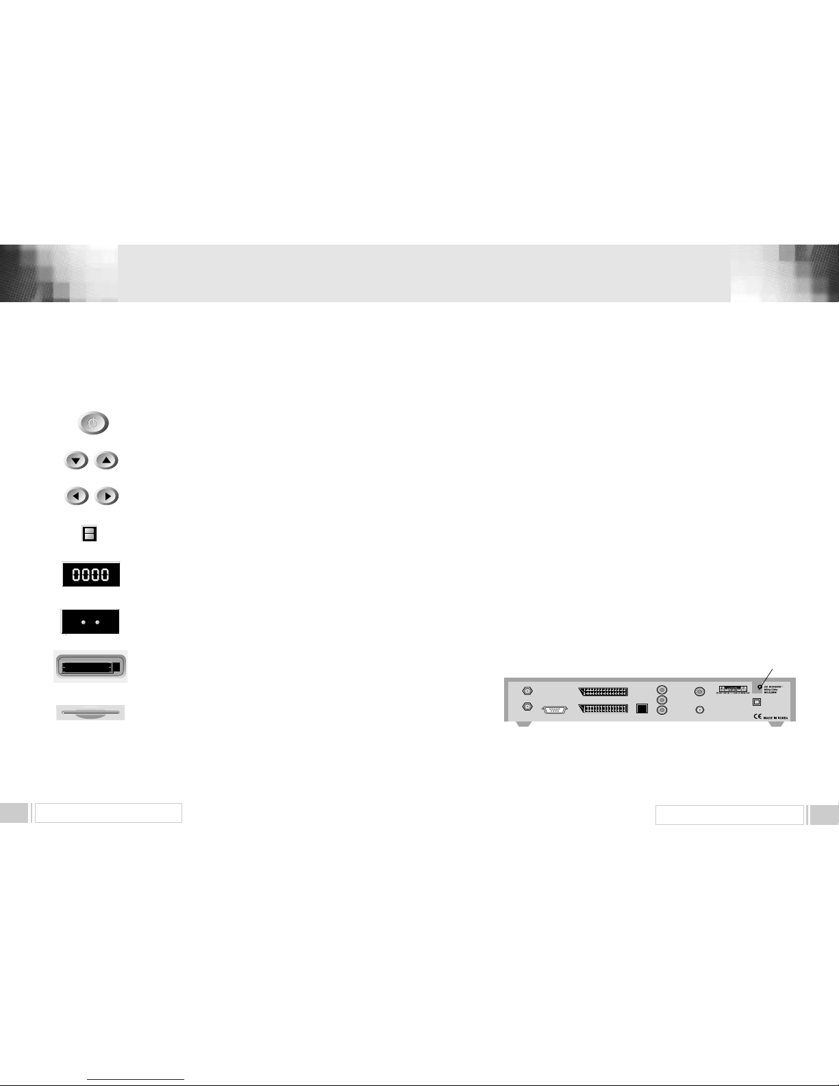
1) POWER : This key is used to turn the receiver on and off (stand by).
2) CH : These keys are used to change the channels.
3) VOL : These keys are used to increase and decrease the volume
level manually.
4) INFRARED SENSOR : This is to receive the IR commands from the
RCU. Do not block the view of the sensor.
5) 7 SEGMENT DISPLAY : This SEGMENT display will show the current
channel number.While the receiver is in stand by mode, the display will show
the current time.
7) CI CAMSLOTS : 2 Slots for Common Interface CAM (VIACCESS,
IRDETO, NAGRAVISION, CRYPTOWORKS, CONAX, SECA) with smart
card.(Option for CI model only)
POWER
C H
VOL
INFRARED SENSOR
7 SEGMENT DISPLAY
CI CAM SLOTS
6) LED DISPLAY: This LED display will show the current power mode status.
If receiver is in stand by mode,stand by mode LED will be on. and when
receiver is in on mode, on mode LED will be on.
(Option for LED display model only)
LED DISPLAY
STANDBY ON
8) SMART CARD INTERFACESLOTS : To watch scrambled
channels you should insert a smart card into Smart Card Interface issued the
service provider whom you subscribes to. Therefore you can watch only a
specific range of channels with entitlements in smart card. The smart card
includes information to decipher parameters necessary for descrambling the
program. Please note that the gold chip on the smart card should face
download and inward when you insert when you insert it into Smart Card
Interface. (Option for CAS model only)
SMART CARD
INTERFACESLOTS
4. A. FRONT PANEL
4. HARDWARE DESCRIPTION
③
②
⑦
⑥
⑧
⑩
⑨
⑤
④
①
LNB IN
IF OUT
SERIAL PORT
VCR
SPDIF
R
TV
VIDEO
AUDIO L
TV OUT
ANT IN
1) LNB IN : This port is to connect the coaxial cable from LNB of your Dish. The IF input is provided through
this port and the input frequency range is 9502150MHz. Also the voltage switching 13V and 18V is
passed through this port.
2) IF OUT : To enable the connection of an analog receiver, The receiver is provided with this port. Connect
this port to LNB IN port of the other receiver via RF Cable.
3) SERIAL PORT : This is used to connect your receiver with computer through a serial cable.
This port can be used for upgrading software.
4) TV SCART : This is used to connect your TV through SCART.
5) VCR SCART : This is used to connect your VCR.
(When you connect external sets to above two SCART sockets, always use fully featured SCART cables)
6) S/PDIF DIGITAL OUTPUT : This port is for the connection to the exterual Hifi system which has a optical
S/PDIF input interface. (Option)
7) VIDEO, AUDIO R/L : These RCA connectors are used to connect any external video and audio.
8) ANT IN : This is used to connect your local RF channels to your TV through Loop.(Option)
9) TV OUT : This is used to connect your TV through RF cable.(Option)
10) POWER INPUT : This is to plug in the AC mains power cord.
The input AC volts range is 90V to 240V, 50Hz/60Hz supply.
4. B. REAR PANEL
 Loading...