

Page 1
K7 Hardware User Manual
Version of 1.0
Release: 2010-09-27
Page 2
Revision history
Rev
Date
Description
1.0
2010-09-27
Initial version
Page 3

Contents
Chapter 1: Overview ................................................................................................... 1
1 System Overview ................................................................................................... 1
1.1 Introduction ...................................................................................................... 1
1.2 Architecture Diagram ....................................................................................... 1
Chapter 2: Hardware System .................................................................................... 3
2 Hardware Overview ............................................................................................... 3
2.1 Hardware Resource ........................................................................................ 3
2.3 Mechanical Parameters .................................................................................. 3
2.4 Schematic ........................................................................................................ 3
3 Hardware Specification .......................................................................................... 4
3.1 Power Input ..................................................................................................... 4
3.2 USB_DEVICE.................................................................................................. 4
3.3 USB_HOST ..................................................................................................... 4
3.4 AUDIO_OUT.................................................................................................... 4
3.5 TV_OUT .......................................................................................................... 5
3.6 Micro_SD ......................................................................................................... 5
3.7 SIM_CARD ...................................................................................................... 6
3.8 Mini PCI_E ...................................................................................................... 6
3.9 KEY_PAD ........................................................................................................ 8
3.10 UART ............................................................................................................. 8
3.11 TFT_LCD ....................................................................................................... 9
3.12 CAMERA ..................................................................................................... 10
Maintenance Service ................................................................................................ 11
Page 4

1
Chapter 1: Overview
1 System Overview
1.1 Introduction
K7 is an MID (Mobile Internet Devices) developed by OpenSourceMID.org community
members. It is based on TI OMAP 3530, a high performance processor. This product is
flexible, it has a nice shape and powerful functions. It supports camera video input,
3G/Wi-Fi wireless network, Bluetooth data transmission, GPS Navigation and G-sensor. It
has a touch screen with high definition and high hardness. Windows Embedded CE 6.0
will be pre-installed when it leaves the factory.
Figure 1 Product photo
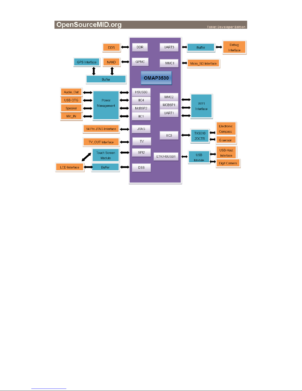
1.2 Architecture Diagram
Figure 2 is the architecture map for K7 and peripheral equipment of this board is also
shown.
Page 5
2
Figure 2 Architecture diagram
Page 6

3
Chapter 2: Hardware System
2 Hardware Overview
2.1 Hardware Resource
Processor:
OMAP3530 processor
600-MHz ARM Cortex™-A8 Core
430-MHz TMS320C64x+™ DSP Core
Intergrated L1 memory for ARM CPU (16kB I-Cache, 16kB D-Cache, 256kB L2)
and On-Chip memory (64kB SRAM, 112kB ROM)
Memory:
256MB DDR SDRAM, 32bit
256MB NAND Flash, 16bit
Interfaces:
2 x USB 2.0 HOST, High-Speed, 480Mbps
1 x USB 2.0 Device, High-Speed, 480Mbps
1 x TV-out interface
1 x Audio output interface
1 x mini PCI-E interface
1 x Micro SD interface
1 x SIM card interface
1 x UART debug interface
2.3 Mechanical Parameters
Mainboard dimension: 207mm x 113mm
Input Voltage: +5V
Power Consumption: 1.4A @ 5V
Temperature Range: 5℃ ~ 40℃
Humidity Range: 20% ~ 90%
2.4 Schematic
Please refer to the hardware section in the Micro SD card.
Page 7

4
3 Hardware Specification
3.1 Power Input
Function: to provide 5V voltage and 2A current for K7
Description of interface: please see table 3-1.
Pin
Signal
Function
1
+5V
Power supply (+5V) 2A (Type)
2
GND
GND
Table 3-1 Power Input interface
3.2 USB_DEVICE
Function: K7 上的 USB_DEVICE interface
Description of interface: please see table 3-2
Pin
Signal
Function
1
VBUS
+5V
2
DN
USB Data-
3
DP
USB Data+
4
ID
DEVICE_ID
5
GND
GND
Table 3-2 USB_DEVICE interface
3.3 USB_HOST
Function: USB_HOST interface on K7
Description of interface: please see table 3-3
Pin
Signal
Function
1
VBUS
+5V
2
DN
USB Data-
3
DP
USB Data+
4
GND
GND
Table 3-3 USB_HOST interface
3.4 AUDIO_OUT
Function: A standard Audio_Out interface
Page 8

5
Description of interface: please see table 3-4
Table 3-4 Audio_Out interface
3.5 TV_OUT
Function: A standard TV_Out interface.
Description of interface: please see table 3-5
Pin
Signal
Function
1
GND
GND
2
TV_OUT
TV analog output Composite
Table 3-5 TV_OUT interface
3.6 Micro_SD
Function: A standard Micro_SD interface
Description of interface: please see table 3-6
Pin
Signal
Function
1
DATA2
MMC1 card data2
2
DATA3
MMC1 card data3
3
CMD
MMC1 card command
4
VDD
3.0V Power
5
CLK
MMC1 card clock
6
VSS
GND
7
DATA0
MMC1 card data0
8
DATA1
MMC1 card data1
9
SW2
SDCD
10
PGND1
GND
Table 3-6 MICRO_SD interface
Pin
Signal
Function
1
GND
GND
2
NC
NC
3
Right
Right output
4
NC
NC 5 Left
Left output
Page 9

6
3.7 SIM_CARD
Function: A standard Sim_Card interface
Description of interface: please see table 3-7
Pin
Signal
Function
1
VCC
UIM power
2
GND
GND
3
RST
UIM reset
4
VPP
UIM Vpp
5
CLK
UIM clock
6
I/O
UIM data intput/output
7
DATA0
NC
8
MCMD
NC 9 CD_DT
NC
10
GND1
GND
Table 3-7 SIM_CARD interface
3.8 Mini PCI_E
Function: A standard mini PCI_E interface
Description of interface: please see table 3-8
Pin
Signal
Function
1
WAKE
3G wake
2
3.3V_1
3.3V power
3
RESERVED1
NC
4
GND1
GND
5
RESERVED2
VREG_MSMP
6
1.5V_1
NC
7
CLKREQ
NC
8
UIM_PWR
UIM card power
9
GND2
GND
10
UIM_DAT
UIM card data
11
REFCLK-
NC
12
UIM_CLK
UIM card clock
13
REFCLK+
NC
Page 10
7
14
UIM_RESET
UIM card reset
15
GND3
GND
16
UIM_VPP
UIM card vpp
17
RESERVED3
NC
18
GND4
GND
19
RESERVED4
NC
20
RESERVED5
KPDPWR_N
21
GND5
GND
22
PERST#
3G reset
23
RERN0
NC
24
3.3VAUX
Auxiliary 3.3V support
25
PERP0
NC
26
GND6
GND
27
GND7
GND
28
1.5V_2
NC
29
GND8
GND
30
SMB_CLK
NC
31
PETN0
NC
32
SMB_DATA
NC
33
PETP0
NC
34
GND9
GND
35
GND10
GND
36
USB_D-
Usb data-
37
RESERVED6
NC
38
USB_D+
Usb data+
39
RESERVED7
3.3V power
40
GND11
GND
41
RESERVED8
3.3V power
42
LED_WWAN#
3.3V power
43
RESERVED9
NC
44
LED_WLAN#
NC
45
RESERVED10
NC
46
LED_WPAN#
NC
Page 11

8
47
RESERVED11
NC
48
1.5V_3
NC
49
RESERVED12
NC
50
GND12
NC
51
RESERVED13
NC
52
3.3V_2
3.3V power
Table3-8 mini PCI_E
3.9 KEY_PAD
Function: A standard Key_Pad interface
Description of interface: please see table 3-9
Pin
Signal
Function
1
VDD33
3.3V power
2
SATA1
SATA1
3
VDD18
1.8V power
4
KPD_C0
Keypad atrix column 0 output
5
KPD_R0
Keypad matrix row 0 intput
6
GND
GND
7
HALL_RIGHT
Right
8
HALL_LEFT
Left
9
HALL_UP
Up
10
HALL_DOWN
Down
11
VABAT_DUAL
Vbat input
12
POWERON
Power on
Table 3-9 KEY_PAD interface
3.10 UART
Function: UARTdebug interface
Description of interface: please see table 3-10
Pin
Signal
Function
1
VDD33
3.3V power
2
TXD
Transit data
3
RXD
Receive data
4
GND
GND
Page 12
9
Table3-10 UART debug interface
3.11 TFT_LCD
Function: TFT_LCD interface
Description of interface: please see table 3-11
Pin
Signal
Function
1
UD
Select up or down scanning direction
2
LR
Select left or right scanning direction
3
GND7
GND
4
DCLK
Sample clock
5
GND6
GND
6
R0
Red data input(LSB)
7
R1
Red data intput
8
R2
Red data input
9
GND5
GND
10
R3
Red data input
11
R4
Red data input
12
R5
Red data input(MSB)
13
GND4
GND
14
G0
Green data input(LSB)
15
G1
Green data input
16
G2
Green data input
17
GND3
GND
18
G3
Green data input
19
G4
Green data input
20
G5
Green data input(MSB)
21
GND2
GND
22
B0
Blue data input(LSB)
23
B1
Blue data input
24
B2
Blue data input
25
GND1
GND
26
B3
Blue data input
27
B4
Blue data input
Page 13
10
28
B5
Blue data input(MSB)
29
GND0
GND
30
HS
Horizontal Sync Signal intput
31
VS
Vertical Sync Signal intput
32
DE
Data Enable
33
MODE
DE or HV mode control
34
VCC2
3.3V Power voltage for digital circuit
35
VCC1
3.3V Power voltage for digital circuit
36
GNDLED2
Ground for LED circuit
37
GNDLED1
Ground for LED circuit
38
ADJ
Adjust the led brightness with PWM Pulse
39
VLED2
5.0V Power for LED backlight
40
VLED1
5.0V Power for LED backlight
Table3-11 TFT_LCD interface
3.12 CAMERA
Function: Camera interface
Description of interface: please see table 3-12
Pin
Signal
Function
1
VDD50
5.0V Power
2
DM2
D-
3
DP2
D+ 4 GND
GND
Table3-12 Camera interface
Page 14

11
Maintenance Service
Maintenance service clause:
The period of warranty for K7 MID (except LCD) is 90 days effective from sale. The
warranty is invalid if you did not purchase through an authorized distributor and can't
provide the original bill as proof of purchase, you had opened the MID case and the
warranty label has been removed or damaged or altered.
We do not offer maintenance service to LCDs. We suggest the customers first check
the LCD after getting the goods. In case the LCD can not run or no display, customer
should inform us within 7 business days from the moment get the goods.
During the warranty period, the delievery fee which delivery to us should be coverd
by user, we will pay for the return delivery fee to users when the product is repaired.
Please first download the Maintenance application form: RMARequestform and fill in
it, then send this form to the mailbox: support@opensourcemid.org.
Page 15

12
Welcome you to join OpenSourceMID Cmmunity. We expect to have more great
ideas with you.
 Loading...