

Page 1

Free To Air / Multi CAS Embedded Digital Satellite Receiver
DigiTECH 5000F
User Manual
Page 2

1. SAFETY INFORMATION
2. FEATURES
3. CONNECTING YOUR RECEIVER
4. CONTROLS AND FUNCTIONS
4.1 REMOTE CONTROL UNIT
4.2 FRONT PANEL
4.2 REAR PANEL
5. MENU GUIDE
5.1 INSTALLATION
5.2 SYSTEM CONFIGURATION
5.3 CHANNEL ORGANIZATION
5.4 PARENTAL LOCK
5.5 RECEIVER INFORMATION
5.6 OTHER FUNCTION
5.7 COMMON INTERFACE
6. TROUBLE SHOOTING
7. TECHNICAL SPECIFICATIONS
2
3
4
6
6
8
9
10
10
12
13
15
15
16
16
17
19
Contents
Page 3
3
2
Be sure to read this User’s Manual before starting the operation of the receiver.
Do not open the cover. It is dangerous to touch the inside of the receiver due to
possible electric hazard.
MAINS SUPPLY : 95�240V AC 50/60Hz
LOCATION : Locate the receiver indoor.
Locate receiver away from potential hazards such as houseplants, lighting, raining and direct sunlight.
OVERLOADING : Do not overload wall outlets, extension cords or adapters as this
can result in fire or electrical shock.
LIQUIDS : Keep liquids away from the receiver.
CLEANING : Before cleaning, disconnect the receiver from the wall socket.
Use a cloth lightly dampened with water (no solvents) to clean the exterior.
VENTILATION : Do not block the receiver ventilation holes. Ensure that free airflow is
maintained around the receiver.
Never set the receiver on soft furnishings or carpets. Do not use or store the receiver
where it is exposed to direct sunlight, or near heater.
Never stack other electronic equipment on top of the receiver.
Place the receiver at least 30mm from the wall.
ATTACHMENTS : Do not use any attachment that is not recommended by the manufacturer,
as it may cause a hazard or damage the equipment.
CONNECTION TO THE SATELLITE DISH LNB : The LNB connector cable has a
voltage in its center core. It is therefore recommended that the receiver is disconnected from
the mains power before connecting or disconnecting this cable.
FAILURE TO DO SO COULD DAMAGE THE LNB.
SERVICING : Do not attempt to service this product yourself. Any attempt to do so will
make the warranty invalid.Refer all servicing to a qualified service agent.
LIGHTNING : If the receiver is installed in an area subject to intense lighting activity,
protection devices for the receiver mains connector and modem telephone line are essential.
The individual manufacturer’s instruction for safeguarding other equipment, such as TV set,
Hi-Fi, etc., connected to the receiver, must also be followed during lighting storms.
GROUNDING : The ground of the LNB cable must be directly connected to the system
ground for the satellite dish. The grounding system must comply with local regulations.
1. SAFETY INFORMATION 2. FEATURES
MPEG-2 & Fully DVB Compliant
MPEG-2 Video (MP@ML), MPEG-1 Audio Layer1,Layer2
PLL RF-Modulator UHF 21~69 with PAL B/G,I, D/K
LNB Controlling Logic (0/22KHz Tone, 13/18V)
SCPC/ MCPC Receivable from C/Ku-Band Satellite
Digital Tuner with Loop-through
Wide Symbol Rate 1~45Mbps & Frequency Input 950~2150MHz
DiSEqC1.2 Supported
2 SCART for TV, VCR
User friendly OSD Menu with Full Function
256 Colors Graphic User Interface
Multi-language Menu
4-digit 7-segment LED Display
Variable Aspect Ratio (4:3, 16:9) with Pan Vector or Letter Box
EPG(Electronic Program Guide) On-screen Channel Information
Small Screen Picture on EPG
Teletext and Subtitle Supported (VBI&OSD)
Installation by Easy Setup Guide
Fast Booting & Auto Scan
Quick Channel Changing
Max. 4000 Channels(TV & Radio) Programmable
Radio Channel Background Display
Favorite Channel List Programmable
Master PIN Code Function & Parental Lock Function
Automatic Detection of Forward Error Correction
Automatic NTSC / PAL Detection and Simple Video Converter
S/W Download Program Supported by RS232 Serial Port
Set to Set Download
3 RCA Output for Video, Audio L/R
Games (SOKOBAN & SLOT machine)
Digital Audio Output : S/PDIF(Option)
Page 4
5
4
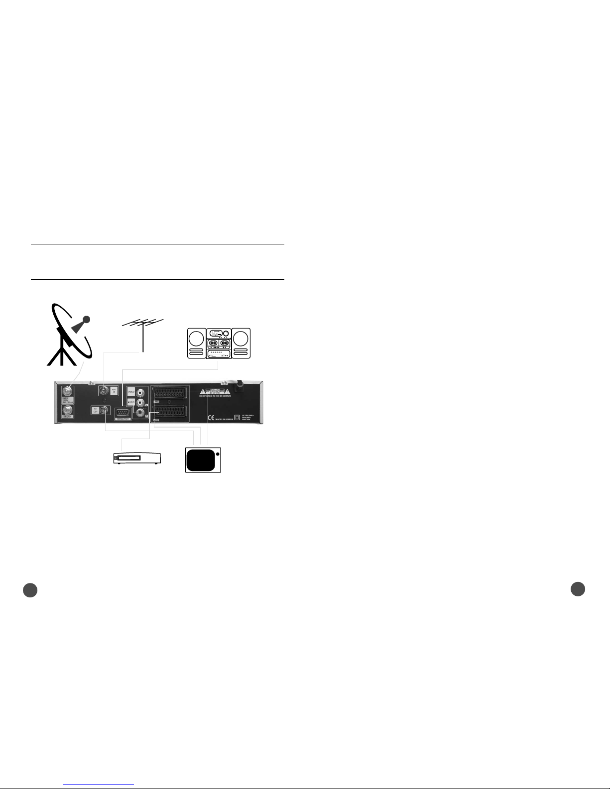
2) CONNECTING THE RECEIVER WITH DISH SYSTEM
After installing your dish system, connect the coaxial cable from LNB of your dish antenna to
“LNB IN”terminal marked at the rear of the receiver.
All cable connectors should be finger tightened ; do not use any kind of wrench
on the cable over connectors.
The cable should be 75Ϊ impedence coaxial twisted at the end with a “F”type connector.
3) CONNECT RECEIVER TO A TV SAT
Connect your receiver to a TV sat with SCART, if your TV set is equipped for it.
Alternatively you can use A/V or TV out(UHF).
4) CONNECT RECEIVER TO A VCR
Connect the SCART jack from the VCR to the back of your receiver.
Alternatively you can use A/V or TV out(UHF).
5) CONNECT RECEIVER TO A Hi-Fi SYSTEM
Connect a RCA stereo cable from the AUDIO L/R jacks, S/PDIF on your receiver to the LINE,
AUX, SPARE or EXTRA input jacks on your Hi-Fi System.
6) CONNECT RECEIVER TO A DIGITAL AUDIO SYSTEM
If you have DAC with S/PDIF optical cable input, you can connect the STB with it to enjoy
higher quality sound. Connect S/PDIF optical cable to a digital amplifier.
7) LOOP THROUGH
If you have another analogue or digital receiver and you wish to use the same LNB then you can
connect it via the loop through. Connect one of end the coaxial cable to the “IF OUT” on the
receiver and connect the other end to the “LNB IN” on your second receiver.
Now by keeping the receiver in standby,
you will be able to tune and view the channels from the receiver.
1) LOCATION OF THE RECEIVER
Your receiver should be placed under proper ventilation.
Don’t put in completely enclosed cabinet that will restrict the flow of air, Resulting overheating.
The location should be safeguarded from direct sunlight, excess moisture,
rough handling or household pets.
Avoid stacking other electronic components on the top of the receiver.
The location should be safely accessible by the cable from your antenna system.
3. CONNECTING YOUR RECEIVER
There are several ways of connecting the receiver to your TV, VCR and / or Hi-Fi
SYSTEM. Consult your local supplier for assistance in setting-up your system that is
best suited to your requirements.
SATELLITE
ANTENNA
VCR
Hi-Fi Stereo Audio
TV
ANTENNA
TV
Page 5
7
6
4. CONTROLS AND FUNCTIONS
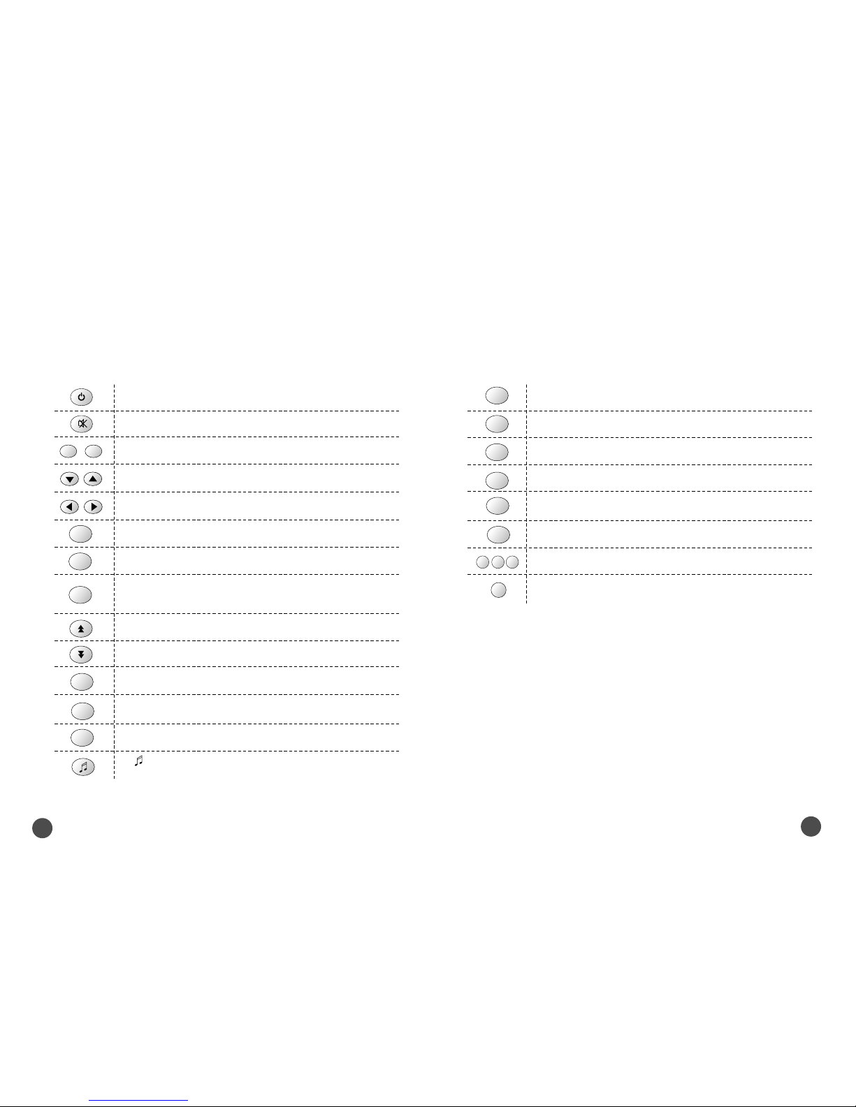
4. 1. REMOTE CONTROL UNIT
1) POWER : This is used to switch the receiver to ON/STANDBY mode.
2) MUTE : This key is used to toggle between normal and muted audio.
3) 0-9 NUMERIC KEYS : These keys are used to enter numeric values and
to select the channel directly by entering its number.
4) CH
▲▲
∙∙
CH▼▼: These keys are used to change channels and to browse
the menu.
5) VOL
▶▶
∙∙
VOL◀◀:These keys are used to control the volume level and to
change the cursor options in the menu.
6) MENU : This key is used to open up the menu.
7) EXIT : This key is used to exit from any menus.
8) OK : This key is used to enter or confirm any data in the menu
systems.The Channel list can be accessed directly by pressing this Key in
the normal view mode.
9) Page Up : This key is used to page up the menu.
10) Page Down : This key is used to page down the menu.
11) FAV : This key is used to switch between favorite lists.
12) GUIDE : This key is used to open up the Electronic Program Guide.
13) i : This key is used to view the channel information.
14) : This key is used to toggle between the TV channel and the radio
channel.
15) LAST : This key is used to return to the previous channel.
16) AUDIO : This key is used to select the soundtrack list for the current
service and also used to select audio mode.
17) PAUSE : This key is used to pause the screen.
18) NTSC/PAL : This key is used to convert video mode.
19) SAT : This key is used to select the satellite.
21). F1, F2 and F3 : Function Keys.
22). F4 : Zoom and Function Key.
20) TEXT : This key is for Teletext.
0 ~9
MENU
EXIT
OK
FAV
GUIDE
i
LAST
AUDIO
PAUSE
NTSC
/ PAL
SAT
TV/
SAT
F1 F2 F3
F4
Page 6
9
8
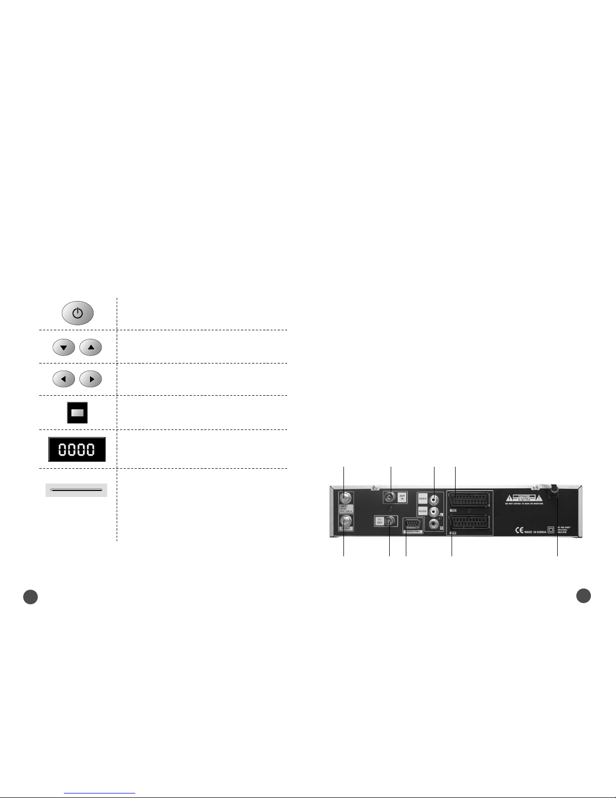
1) LNB IN : This is to Connect the coaxial cable from LNB of your Dish.
2) IF OUT : This is to enable the connection of an other receiver, The receiver is provided with this port.
Connect this port to LNB IN port of the other receiver via RF Cable.
3) ANT IN : This is used to connect your local RF channels to your TV through Loop
4) TV OUT : This is used to connect your TV through RF cable.
5) SERIAL PORT : This is used to connect your receiver with computer through a serial cable.
This port can be used for upgrading software.
6) VIDEO, AUDIO R/L : These RCA connectors are used to connect any external video and audio.
7) TV SCART : This is used to connect your TV through SCART.
8) VCR SCART : This is used to connect your VCR.
9) S/PDIF (DIGITAL OUTPUT) : This port is for the connection to the exterual Hifi system which has a
optical S/PDIF input interface. (Option)
10) POWER INPUT : This is to plug in the AC main power cord.
The input AC volts range is 95V to 240V, 50Hz/60Hz supply.
4. 3. REAR PANEL
4.2. FRONT PANEL
1) POWER : Push the receiver on and off (stand by).
2) CH : Changes the channels and moves the cursor up / down in
menu mode.
3) VOL : Increases and decreases the volume level manually and
changes setting in menu mode.
5) 7 SEGMENT DISPLAY : This SEGMENT display will show the
current channel number.While the receiver is in stand by mode,
the display will show the current time.
4) INFRARED SENSOR : This is to receive the IR commands from
the RCU. Do not block the view of the sensor.
6) SMART CARD INTERFACE SLOTS : To watch scrambled
channels you should insert a smart card into Smart Card Interface
issued the service provider whom you subscribes to. Therefore
you can watch only a specific range of channels with entitlements
in smart card. The smart card includes information to decipher
parameters necessary for descrambling the program. Please note
that the gold chip on the smart card should face download and
inward when you insert when you insert it into Smart Card
Interface. (Option for CAS model only)
①
②④⑤⑧ ⑩
③⑥⑦
Page 7
11
10
Main Menu
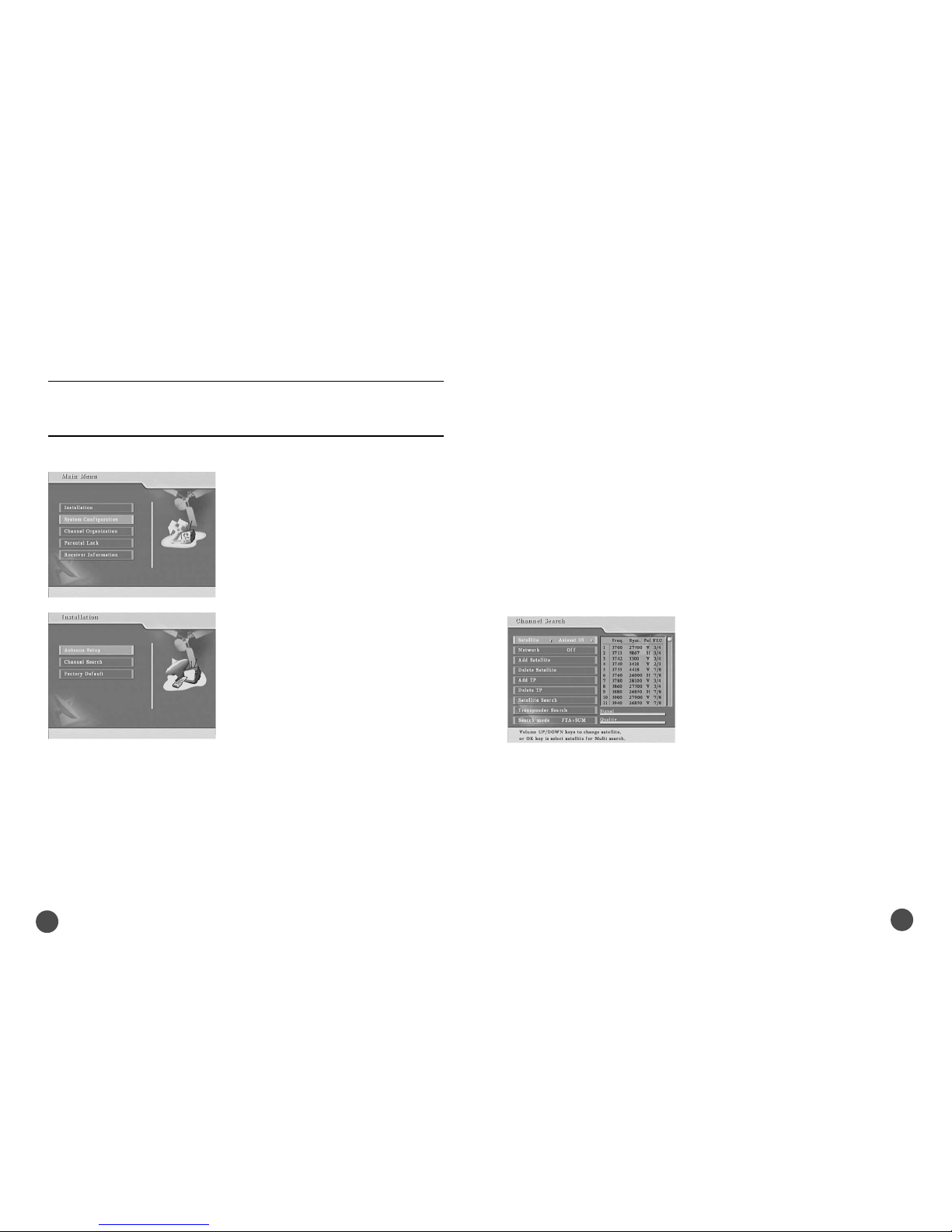
Press the “MENU” key in the RCU. You will see
the “Main Menu” on the screen.
1) You can move into the desired submenu using
“UP” key or “DOWN” key.
2) Press “OK” key to confirm your selection.
3) Press the “MENU” key or “EXIT” key to return
to previous menu.
5.1. Installation
This is to install Antenna Setup, Channel Search,
Factory Default and Code.
5.1.1 Antenna Setup
In this menu you can see satellite information and
antenna (dish) setup.
Select theSatellite, LNB Power, LNB Type, LNB
High, LNB Low, 22KHz, DiSEqC Type or DiSEqC
1.2 motor.
Press “OK” key to move to Channel Search menu after storing your selection in Antenna
Setup.
a. Satellite : You can select the desired satellite using the volume “UP/DOWN” (◀∙▶)
keys.
b. LNB Power : You can select the LNB Power ON or OFF. Using the volume
“UP/DOWN” (◀∙▶) keys.
c. LNB Type : You can select the Universal LNB or Standard LNB. Using the volume
“UP/DOWN” (◀∙▶)keys.
d. LNB High : You can select the LNB Frequency. Using the volume “UP/DOWN”(◀∙▶)
keys or numeric keys.
e. LNB Low : If you can use the Universal LNB, you can select the LNB low frequency.
Using the volume “UP/DOWN” (◀∙▶)keys or numeric keys.
f. 22KHz : If you have 22KHz tone box, you can supply either 22KHz by setting “ON” or
not by setting “OFF”. Using the volume “UP/DOWN” (◀∙▶)keys or numeric keys.
g. DiSEqC Type : If you have DiSEqC box, you can select and use appropriate port for
your DiSEqC box. Using the volume “UP/DOWN”(◀∙▶)keys.
h . DiSEqC 1.2 motor : If you have DiSEqC 1.2 motor, please select “ On.
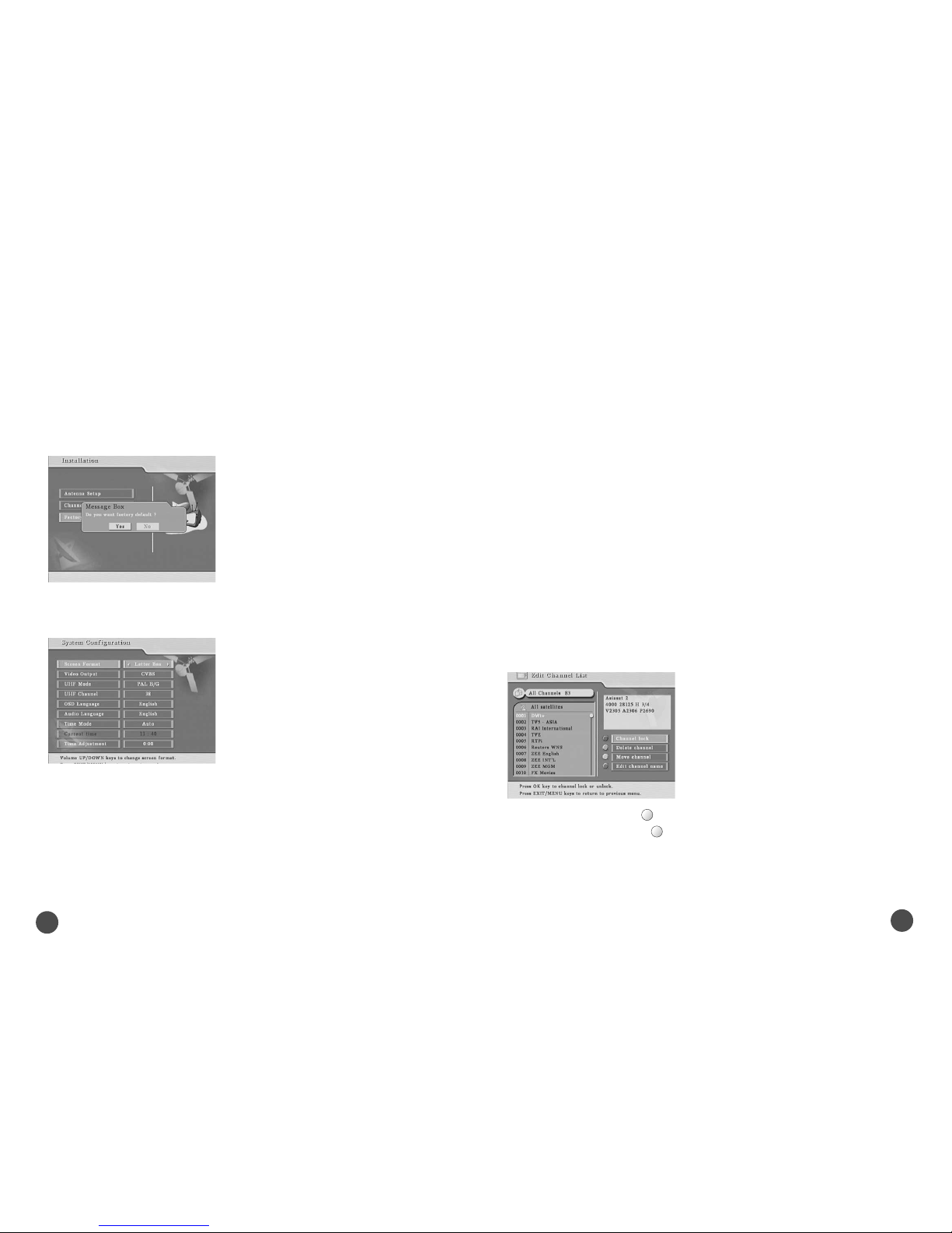
5.1.2 Channel Search
The menu shows all transponders in satellite and
edit satellite, edit transponder to scan the
satellite.
a. Satellite : You can select the desired satellite
using the volume “UP/DOWN”(◀∙▶)keys. If you
want Multi Search, press “OK” key and then
select other satellites.
b. Network : You can select the Network search
using the volume “UP/DOWN”(◀∙▶)keys.
c. Add Satellite : You can add a new satellite
using the “OK” key.
d. Delete Satellite : You can delete USER satellite using the “OK” key.
e. Add TP : You can add a new transponder using the “OK” key.
f. Delete TP : You can delete transponder using the “OK” key.
g. Search mode : You can select the FTA(free to air)+SCM(scrambled) or FTA, SCM
using the volume ‘UP/DOWN”(◀∙▶)keys.
h. Transponder Search : Press “OK” key to start transponder search for selected
transponder.
i. Satellite Search : Press “OK” key to start satellite search for selected satellite.
5. MENU GUIDE
The main menu is classified into five menus which will carry out the various
operation individually.
Page 8
13
12
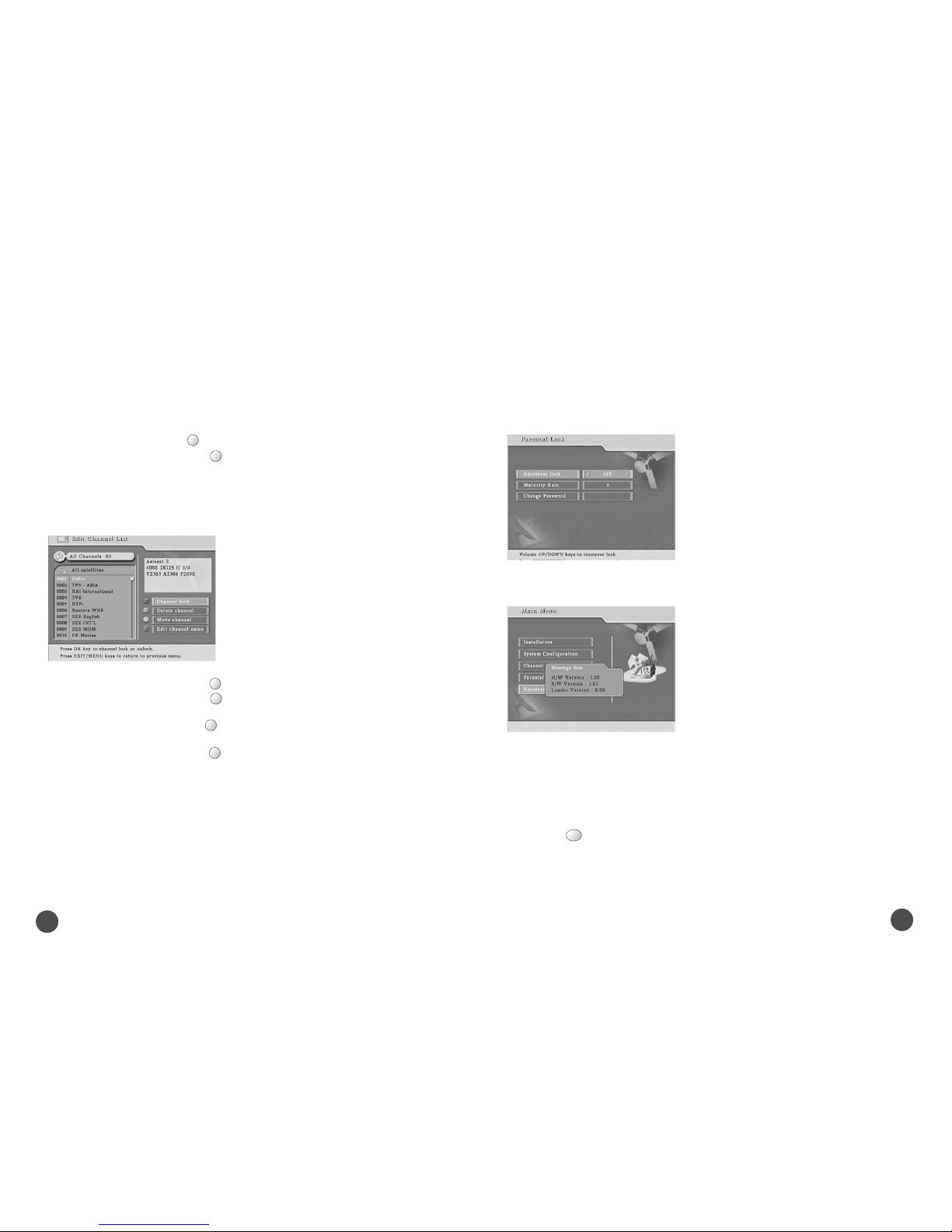
5.1.3 Factory Default
To reset the receiver, select “Factory Default” in
“Installation” and press “Yes” icon on the screen.
The receiver will be reset automatically.
5.2. System Configuration
This menu helps you to set up Screen Format,
Video Output mode, UHF mode, language, time
mode.
a. Screen Format : You can select the screen format (4:3, 16:9, Letter Box) using the
volume “UP/DOWN”(◀∙▶)keys.
b. Video Output : You can select the video output mode (CVBS, RGB) using the volume
“UP/DOWN”(◀∙▶)keys.
c. UHF Mode : You can select the UHF mode (PAL B/G, I, D/K) using the volume
“UP/DOWN”(◀∙▶)keys.
d. UHF Channel : You can select the UHF channel (21 ~ 69) using the volume
“UP/DOWN”(◀∙▶)keys.
e. OSD Language : You can select the OSD language (Menu language) using the
volume “UP/DOWN”(◀∙▶)keys.
f. Audio Language : You can select the audio language using the volume
“UP/DOWN”(◀∙▶)keys.
g. Time Mode : You can select the Time mode (Auto, Manual) using the volume
“UP/DOWN”(◀∙▶)keys.
h. Current time : You can input the time using the numeric keys in case of selecting
“Manual” in Time Mode.
i. Time Adjustment : You can adjust the time using the volume “UP/DOWN”(◀∙▶)keys
in case of selecting “Auto” in Time Mode.
5. 3. Channel Organization
5.3.1 Edit Channel List
This menu helps you to select the channel that you want to watch easily.
a. Channel lock : Press “F1” to lock the channel in the channel list.
b. Delete channel : Press “F2” to delete the channel in the the channel list..
F1
F2
Page 9
15
14
c. Move channel : Press “F3” to move the channel in the the channel list.
d. Edit channel name : Press “F4” to rename the channel in the the channel list.
5.3.2 Edit Favorite List
This menu helps you to select the channel that you want to watch easily.
a. Add to fav. channel : Press “F1” key to add the channel into favorite channel list.
b. Delete fav. Channel : Press “F2” key to delete the channel in the favorite channel
list.
c. Move fav. Channel : Press “F3” key to move the channel in the favorite channel
list.
d. Rename fav. Group : Press “F4” to rename channel in the favorite channel list.
5. 4. Parental Lock
This menu prevents children or unauthorized persons from watching programs.
Also you can change password.
a. Receiver Lock: Select “On” to have Receiver
Lock.
b. Maturity Rate: Select “ Number” to prevent
children from watching..
c. Change Password: Put the new password if
you want to change new password number.
5.5. Receiver Information
It displays receiver information on H/W, S/W
version and Loader version.
5.6 Other Function
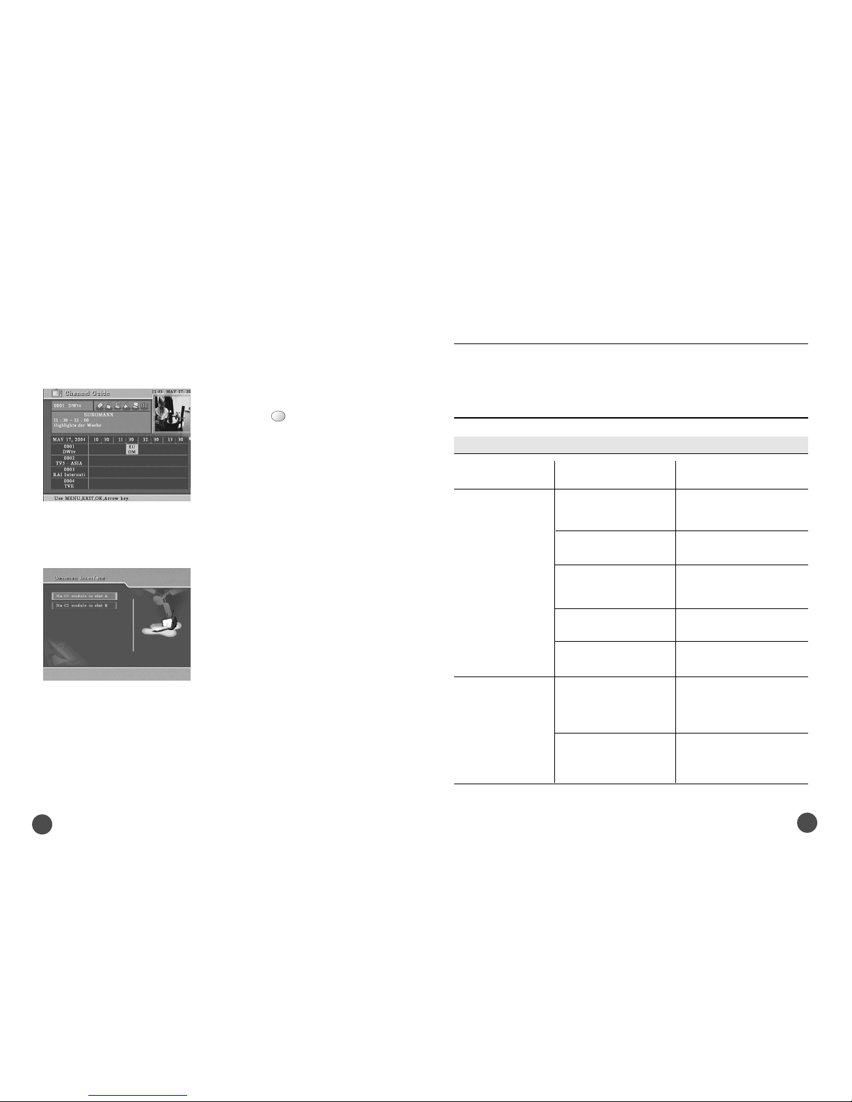
5.6.1. EPG (Electronic Program Guide)
This is to see channel guide information to get current and next channel program
schedules.
Press Guide Key.
F3F4F1
F2
F3
F4
GUIDE
Page 10
17
16
5.6.2. Teletext
This is to get channel date through the stream.
Please press text. Key.
5.6.3. Zoom Function
This is to see a part of the screen in detail.
Press F4 Key and choose a part of screen using
the Volume “UP/Down” and CH. “UP/Down” keys.
And press “OK” key. The part of the screen is
extened.
6. Common Interface (Option function)
This receiver is equipped with two slots of
Common Interface.
When a common interface CAM is inserted inside
the PCMCIA slot, the receiver detects the type of
the CAM automatically and display in the menu.
6. TROUBLE SHOOTING
There may be various reasons for the abnormal operation of the receiver.
Check the receiver according to the procedures shown below .
If you can’t solve the problem even after referring this trouble shooting, please
contact the dealer. Don’t open the receiver cover. It may cause a dangerous
situation.
Symptom Cause Result
The front panel doesn’t
display any message
No picture or sound.
No picture.
The power cord is not
plugged in
Wrong connection in the
Audio / Video output of the
receiver to TV.
Wrong connection of the
satellite antenna.
No or Bad signal message
appears.
Audio muting.
TV power off.
The receiver can’t receive
the signal.
Incorrect values of some
tuner parameters.
Check other device connected
between LNB and the receiver,
or adjust the antenna position.
press the MUTE button.
Turn TV on
Check the antenna cable,
replace the cable, or connect
the cable to the receiver tightly.
set the values of tuner
parameters correctly in the
Installation Menu.
Check that the power cable is
plugged in to the wall outlet.
Connect the Audio / Video
output of the receiver to TV
correctly.
Connect the antenna cable
correctly.
TEXT
Page 11
19
18
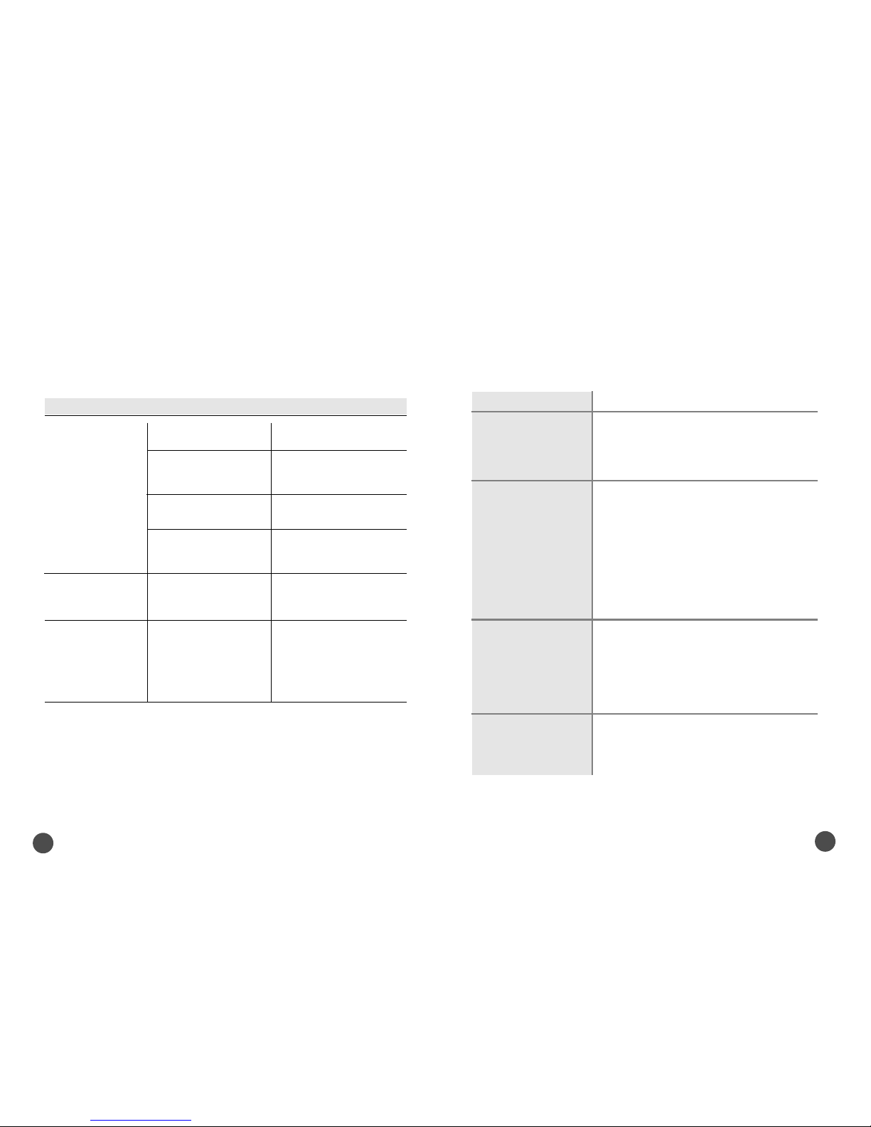
1. Power Supply
Type
Input Voltage
Fuse Rating
2. Tuner
Input Frequency
Input Signal Level
Input Impedance
Connector Type
LNB Power Supply
22KHz Tone
DiSEqC
Channel Selection
3. Demodulator
Type
Symbol Rate
Inner FEC
Outer FEC
4. Video Decoder
System Decoding
Profile and Level
Data Rate
Video Formats
: SMPS
: 95�240VAC 50/60 Hz
: 250V/T2A
: 950�2150MHz
: -65�-25dBm
: 75Ϊ Unbalanced
: ‘F’Type Female
: 13V/18V, Max 500mA with Short Circuit Protection
: Frequency 22± 4KHz, Amplitude 0.6±0.2Vpp
: 1.0 & 1.2 Version Compatible
: PLL Frequency Synthesizer
: QPSK Demodulation(DVB-S)
: 1�45 MS/s
: Viterbi Convolutional Coding
Rate 1/2, 2/3, 3/4, 5/6, 7/8
: Reed Solomon Coding(204,188) T=8
: MPEG-2 ISO/IEC 13818-2
: MPEG-2 MP@ML
: 1�15 MB/s
: 4:3(Normal) & 16:9(Widescreen)
Symptom Cause Result
No or bad signal
You have forgotten
your PIN number
The remote controller
does not operate.
The satellite dish is not
pointing at the satellite.
Signal too strong
Satellite dish is too small.
The LNB is faulty.
The batteries of the remote
controller are not inserted
or exhausted.
Change the LNB.
Contact your dealer, and then
reset your receiver.
Check whether the batteries
are inserted correctly in your
remote controller.
Check and replace the
batteries of the remote
controller.
Adjust the dish.
Connect the signal attenuator
to the LNB input.
Change to a larger dish.
7. TECHNICAL SPECIFICATIONS
Page 12
20
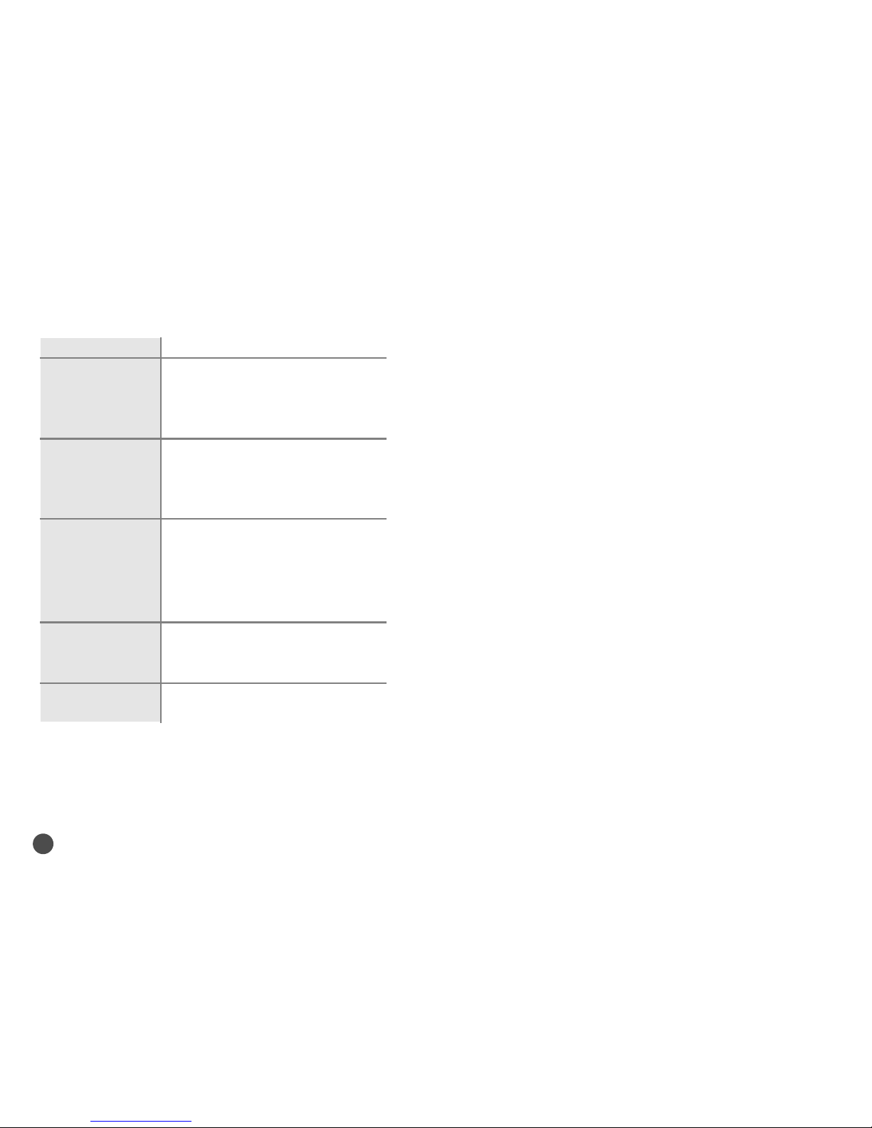
5. Audio Decoder
System Decoding
Audio Mode
Sampling Frequency
6. Audio/Video Output
TV SCART
VCR SCART
RCA Jack
S/PDIF (Option)
7. RF Modulator
Modulator Output
Video Type
UHF Output Level
Output Connector
Ant. IN Connector
Tuning Method
8. Serial Data Interface
Signal
Connector Type
9. Common Interface
Module Type
Available CAM
: MPEG-1 ISO/IEC 11172-3
Layer I & II
: Mono, Dual, Stereo, Joint Stero
: 32, 44.1, 48 KHz
: CVBS, RGB, Audio L/R
: CVBS, Audio L/R
: CVBS, Audio L/R
: Digital Audio
: CH21�69 (Preset To CH38)
: PAL B/G, I, D/K
: 71±4 dBμV
: IEC Male
: IEC Female
: PLL Frequency Synthesizer
: RS-232, Max. 38400 bps
: 9 Pin D-Sub(male)
: PCMCIA Type II×2
: Viaccess, Irdeto, Nagravision, Cryptoworks,
Conax, SECA
 Loading...