

Page 1

bre
network
Developer Guide
Version 7.1 – August 2018
How to build a
Page 2

2.
Home
wiring
5.
Multi dwelling
Units (MDUs)
8.
Modular jointing
chambers –
Quadbox
TM
3.
Developer
self-install
6.
Commercial
units
11.
Health and
safety advice
9.
Joint boxes,
footways and
frames & covers
4.
Cabling
and ONT
positioning
7.
Duct laying
10.
List of
abbreviations
and acronyms
CON
TENTS
1.
Internal
equipment
12.
Quality control
checklist
Page 3
3
Internal equipment
1
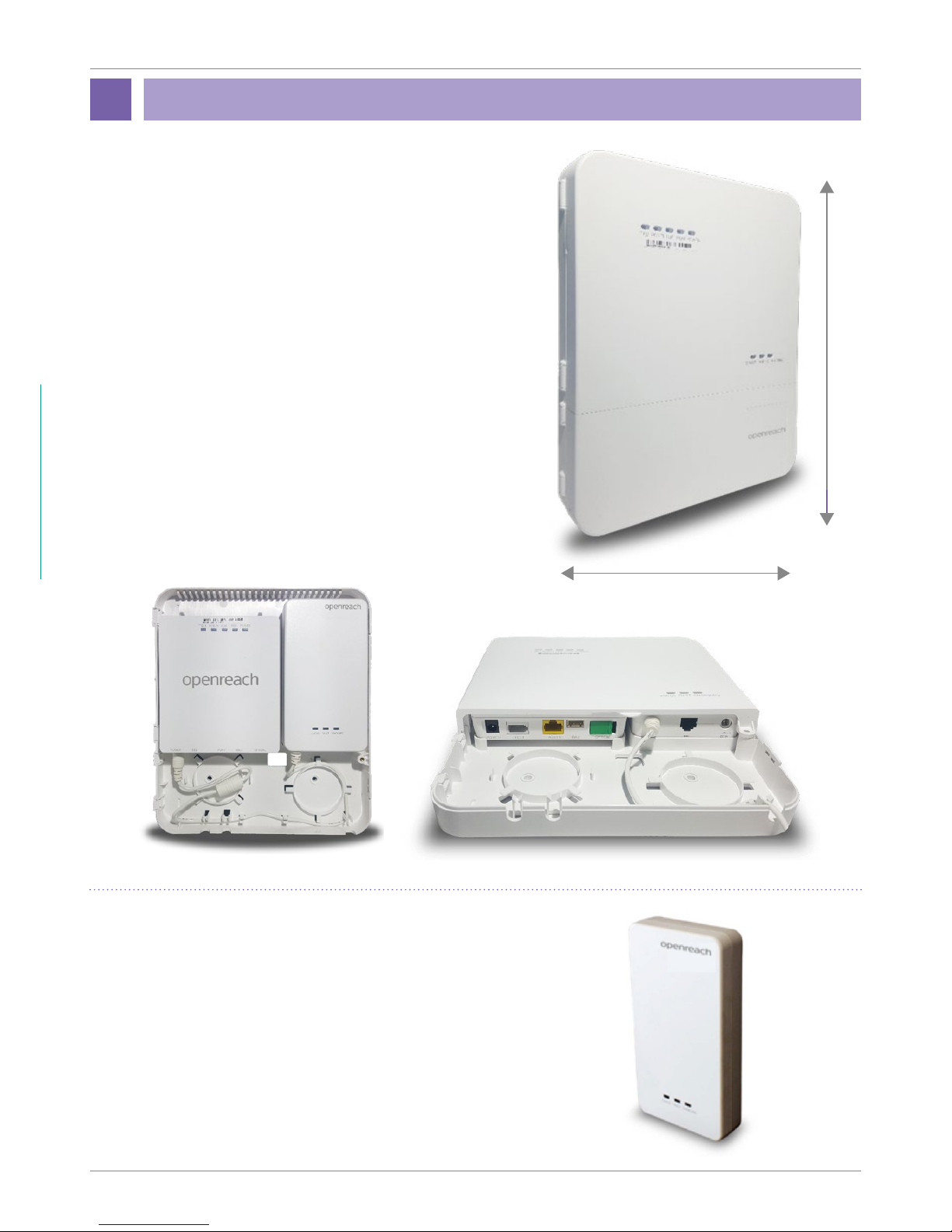
The ONT is the Openreach demarcation point.
It replaces the traditional copper master socket.
The Openreach ONT sits in an enclosure along with
the Battery Backup Unit (BBU) and associated wiring,
keeping everything neat and tidy. The enclosure is
designed for simple wall mounting with just 2 screws.
• Optical port connects to the external
Customer Splice Point.
• Ethernet port connects to the
communications provider's (CP) router.
• Telephony port connects to voice network.
Openreach Optical Network
Termination (ONT) and enclosure
254mm
215mm
Battery Backup Unit (BBU)
The BBU sits in the enclosure along with the ONT. It supports
voice calls for approximately an hour should there be any
interruption to the mains power supply.
A red warning light will ash when a replacement battery is
required. Openreach warranties the battery for 90 days, where
it then becomes the responsibility of the home owner.
How to build a fibre network - version 7.1
Page 4
4
Openreach: Developer Guide
Internal equipment
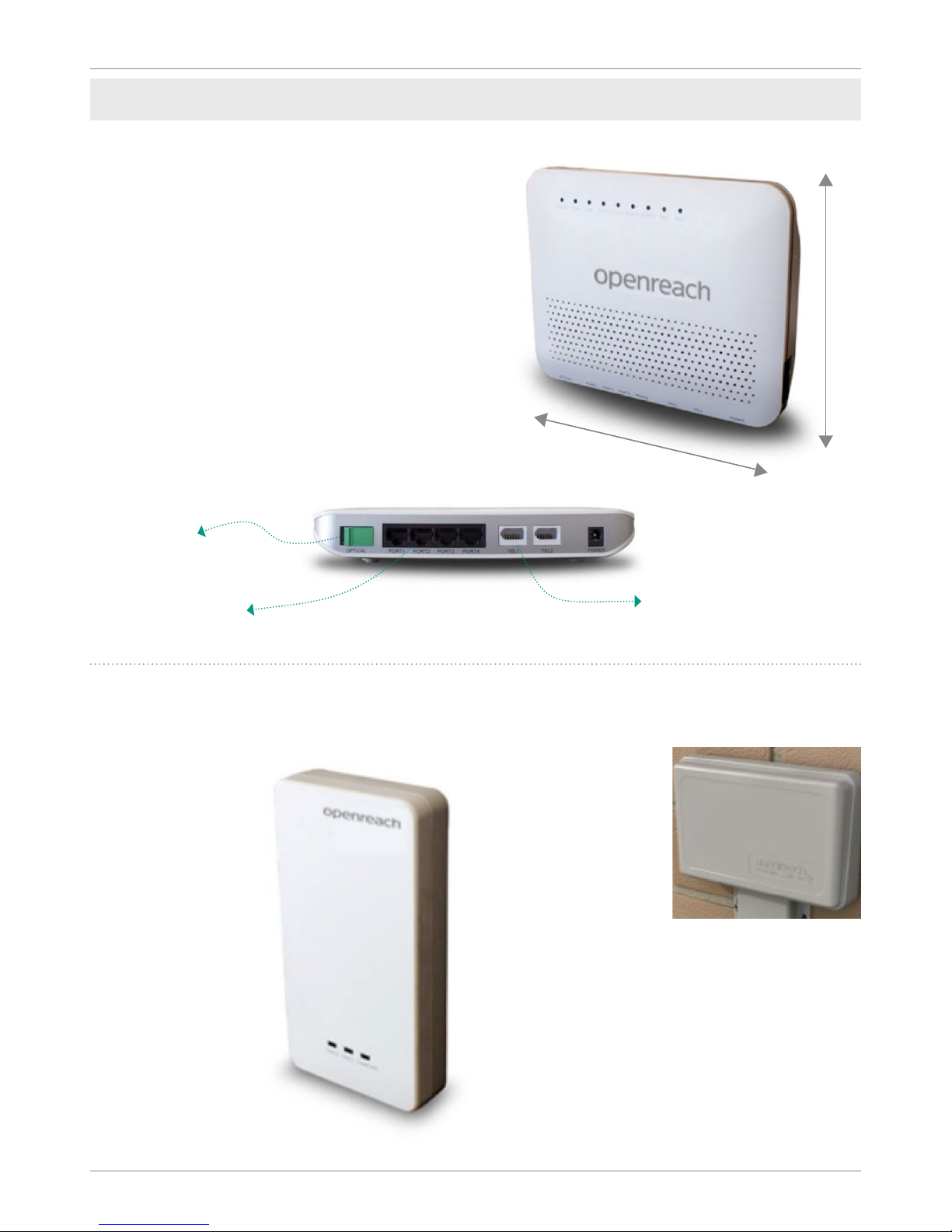
Legacy ONT
The legacy ONT was the previous piece of
equipment used before the introduction of the
1+1 in January 2018.
This ONT is mounted directly to the wall and has
no associated enclosure.
• Optical port connects to the external
Customer Splice Point.
• Ethernet ports connect to the CP router.
• Telephony ports connect to voice network.
155mm
195mm
Optical
port
Ethernet
ports
Telephony
ports
The CSP houses
the external
connectorised
bre cable and
the connected end
that ts into the
ONT. The CSP sits
of the outside of
the house.
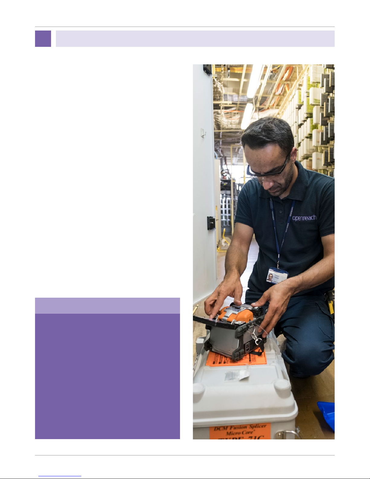
Where you self-install there will be no internal
CSP, instead the connectorised cable will plug
directly into the ONT. If the connectorised
cable end is damaged during installation
then an internal CSP may be required to be
tted to complete installation. This will be
undertaken at the commissioning stage by
Openreach. Your Field Based Co-ordinator
(FBC) will guide you through this.
BBU
The battery backup
supports voice calls
for approximately
one hour should
there be any
interruption to the
mains power supply.
A red warning light
will ash when
a replacement
battery is required.
Openreach
warranties the battery
for 90 days, where
it then becomes the
responsibility of
the home owner.
Customer Splice Point (CSP)
Page 5
5
The wiring that you install in your customer’s
properties is pivotal to their experience.
Your options in the installation
of internal wiring are shown
as below
Implications of locating the service
provider’s router in a cupboard
It is important to note that the Wi-Fi service
your customer receives is dependent upon
the intended location of the communication
provider’s router. Placing the router in a
service cupboard or under stairs cupboard will
signicantly reduce the speed and coverage
your customer will receive.
It is highly recommended that if you position
the router in this way that you provide additional
RJ45 ports within the home. Ideally for optimum
speeds to be enjoyed using Wi-Fi service it
is recommended that you locate the router
centrally within the property.
For information, advice and guidance around
positioning, please refer to: PAS: 2016 Next
Generation Access for new Build Homes Guide.
All internal wires and sockets beyond the
ONT are the responsibility of the developer/
future home owner.
If any part of the connectorised internal
bre cable is found to be damaged at
commissioning, it is the developer’s
responsibility to replace it.
If the homeowner experiences a lack of
service or poor service, which is due to
a fault within the internal installation
of wiring, which requires Openreach to
rectify, the homeowner will be charged.
Please note
Home wiring
2
How to build a fibre network - version 7.1
Page 6
6
Openreach: Developer Guide
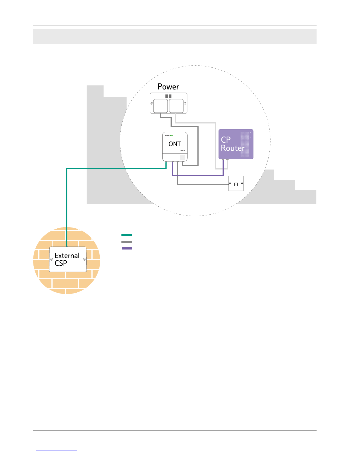
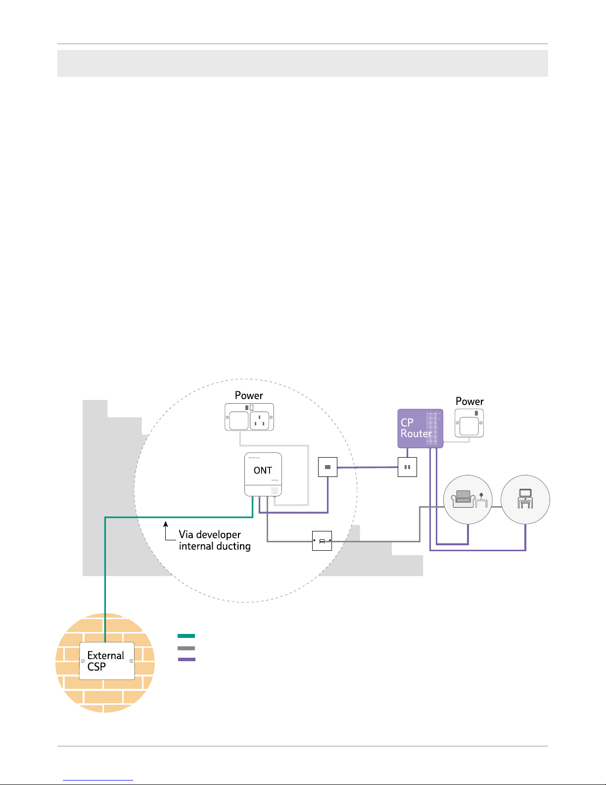
The simple install
The simplest installation will be the provision of the Openreach equipment
(i.e. the ONT will be positioned adjacent to the outside wall) to which the customer
then attaches the router, provided by their communications provider. Without
internal data cabling, this relies on wireless extenders using.
the homes electricity cabling system to provide internet connection to other rooms in
the house. Power sockets should be provided for the Openreach equipment and for the
communications provider’s router and for the wireless extenders / adaptors if used.
CSP: Customer Splice Point
ONT: Optical Network Termination
BBU: Battery Backup Unit
Option 1
Connectorised bre cable
Voice cable
Ethernet cable
Home wiring
External
Internal
Page 7
7
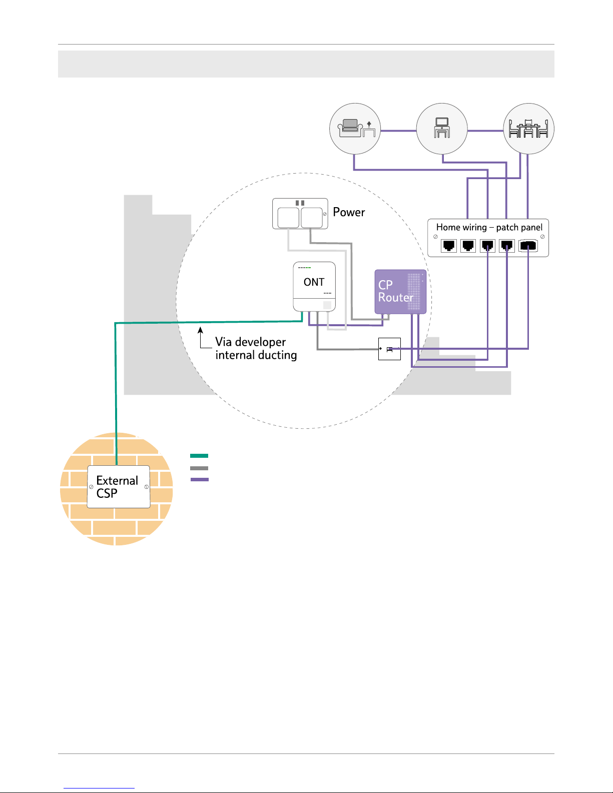
Option 2
Relocating the ONT and BBU
Some developers want to position the v and Battery Backup Unit (BBU) further
inside the property. This will require a longer connectorised internal bre
cable which is recommended to be installed in a protective conduit to the
external Customer Splice Point (CSP) plus the provision of a power socket for
the equipment. Additional Cat6* cabling is required for this option from the
ONT & BBU to connections in the study and living room. These connections
should terminate in an RJ45 socket. A power socket should be provided for the
communications provider’s router, if the router is placed near the RJ45 socket
or a double socket if it is placed by the ONT and BBU.
*Cat6 is the preferred option to ‘future proof’ for modern devices
CSP: Customer Splice Point
ONT: Optical Network Termination
BBU: Battery Backup Unit
Connectorised bre cable
Voice cable
Ethernet cable
Home wiring
How to build a fibre network - version 7.1
Page 8
8
Openreach: Developer Guide
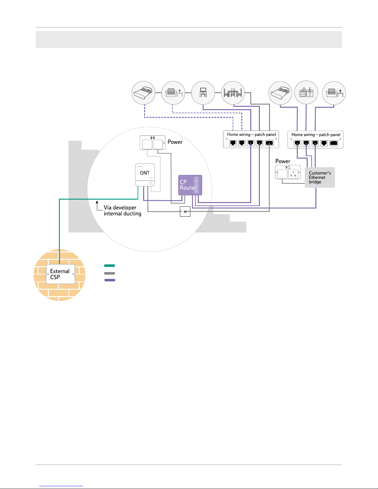
As per option 2 this extends the number of xed sockets so that the home owner doesn’t
need to rely on wireless connections in the majority of the house. This would enable the
down-streaming of 4K television in those areas where the customer is most likely to use
high bandwidth applications like streaming TV, gaming consoles or video conferencing.
One double power socket should be provided for the Openreach equipment and for the
communications provider’s router. We recommend that all the data cabling from the
rooms are terminated in a data patch panel (example as below) in close proximity to
the ONT to facilitate easy connection.
It is also recommended that where an aerial socket is provided for televisions that
an ethernet data socket and associated wiring is also provided.
CSP: Customer Splice Point
ONT: Optical Network Termination
BBU: Battery Backup Unit
Connectorised bre cable
Voice cable
Ethernet cable
Relocating the ONT and BBU and
adding data points in multiple rooms
Home wiring
Option 3
Page 9
9
Home wiring
The networked home
This option offers data cabling from wherever the Openreach ONT & BBU equipment is located,
to all rooms in the home using a home wiring patch panel and RJ45 data sockets throughout.
This could be offered either as standard or a customer paid option and will guarantee the best
customer experience and help differentiate your property.
We recommend that all the data cabling from the rooms are terminated in a data patch panel
in close proximity to the ONT (Optical Network Termination) or the communications provider’s
router to facilitate easy
connection.
Option 4
CSP: Customer Splice Point
ONT: Optical Network Termination
BBU: Battery Backup Unit
Connectorised bre cable
Voice cable
Ethernet cable
How to build a fibre network - version 7.1
Page 10

10
Openreach: Developer Guide
Home wiring
When Openreach install the equipment we will
install the ONT wherever the incoming bre cable
is located. Where you self-install the ONT, you will
have control over when the equipment is installed.
The ONT will remain the property of Openreach in
both installation scenarios.
Where you are self-installing the Openreach
equipment we will supply the ONT, along with the
battery back-up and the connectorised internal
bre cable you need. If you are installing the ONT
opposite the cable entry hole, you will need to install
a ush mounted double back box on the internal
wall where the ONT is to be located.
The ONT will be installed at this location unless an
alternative position has been agreed with your FBC
and the appropriate connectorised internal bre
cable run in a continuous fault-free length to the
alternative position.
While the provision of internal wiring beyond
the Openreach ONT is the responsibility of
the developer, you can contract an Openreach
engineer to do this work for you. If interested,
please contact your local customer network
solutions team on 0800 783 2023. Terms
and Conditions for the provision of internal
wiring will apply.
Provision of the Openreach equipment
Voice Cabling
• Voice extension cabling shall run direct from
the ONT voice port. Connection to the ONT
is made via a BS6312 431A Plug inserted
into voice port 1. This socket must be a slave
socket, not a master socket.
• Extension sockets shall be located close to
power sockets for easy equipment connection.
A minimum of 50mm between telephone
cables and power cables shall be left
throughout.
• Where this isn’t practical, telephone and power
cables must be separated by an acceptable
divider (i.e. of rigid, non-conducting material).
• Extension wiring must be telephone/data
grade and have plain annealed solid copper
conductors of a diameter between 0.5mm and
0.63mm. The conductors shall be in twisted
pair format. The conductor resistance shall
be of a maximum of 96 ohms/km. The cable
sheath shall be PVC.
Data Cabling
• As a rule of thumb connectorised internal
bre cables shall not exceed the minimum
bend radius (i.e. no smaller than) of a £2 coin.
• Detailed information on cable installation and
separation is given in the British Standards.
• Code of Practice 6701, Part 1 (particularly
clause 6) and the relevant sections of the
latest IEE Regulations for electrical Installation
(Regulation 525 is of particular importance).
• The wiring pattern for cabling must be either
in series or spur. For data it must be point to
point as speeds will be impacted after the rst
point of a daisy chain.
• We’d recommend data cabling rooms
likely to benet most from a physical
connection, like the room with the main
TV and the home ofce.
Please note: If connectorised cable is damaged by developers during installation then an
internal Splice Point may be required to be tted to complete installation. This will be undertaken
at commissioning stage by Openreach.
Installation of internal cabling
How to build a fibre network - version 7.1
Page 11
11
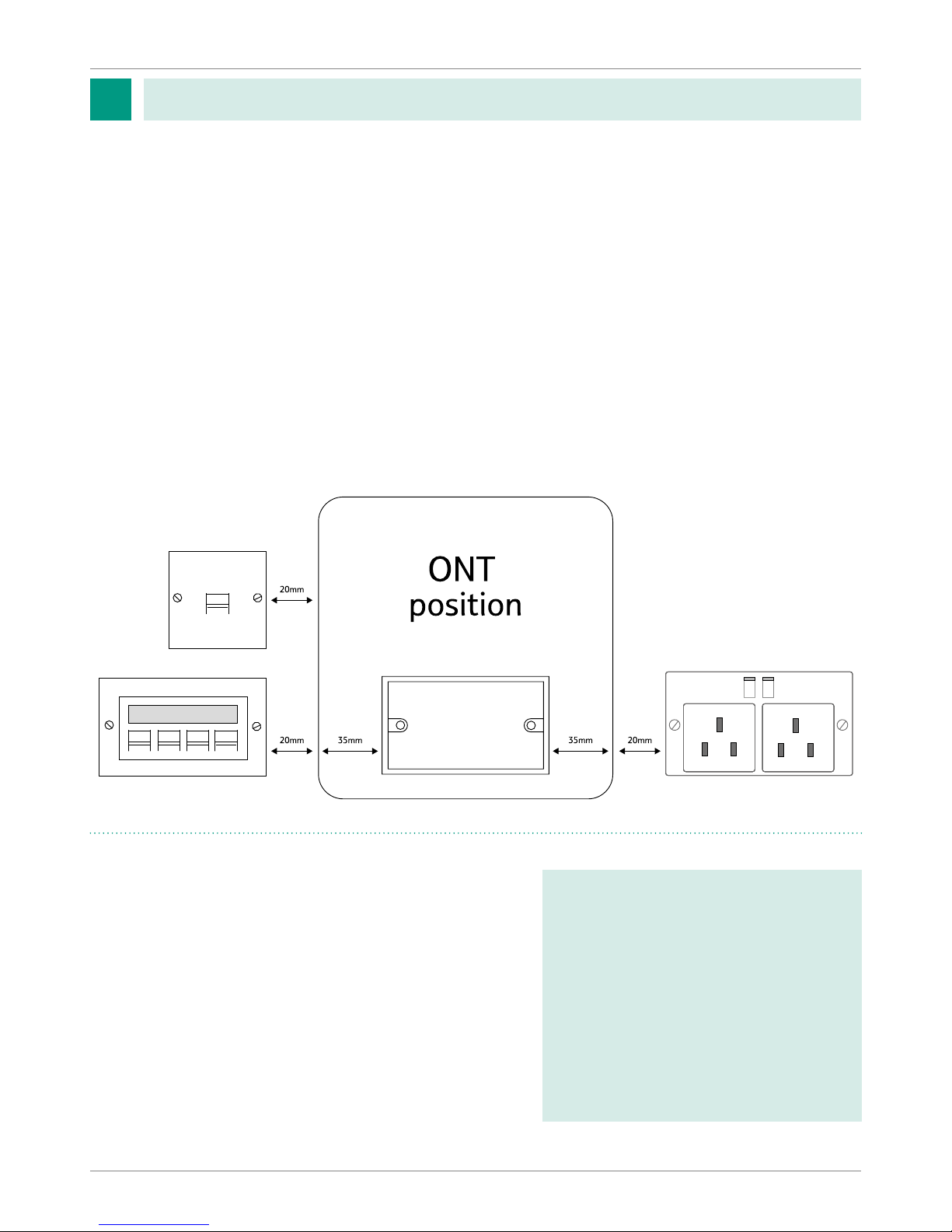
• Fit the double electrical socket to the wall.
• Fit the double back box to the wall.
• Fit the slave voice socket to the wall (can be modular to house one voice port and one data port).
• Fit RJ45 modular boxes. The number of these are to be determined by you the developer
Openreach recommend a minimum of two are tted, one for the communications provider
router and the other to the room requiring streaming media for example for streaming
high denition TV. See the internal wiring section for further information.
• All internal wiring to be run back to this point (daisy chain for voice and point to point for data).
• See below for the recommended layout of sockets on the wall, the layout can be mirrored.
Internal Work at dened ONT and Communications
Provider router position
Single Dwelling Unit at second
x (Internal Work)
• Fit the enclosure to the wall over the double back
box using the supplied template.
• Take the pre-connectorised cable from back box to
the ONT position.
• Connect the BBU to the ONT power port.
• Clean both the pre-connectorised cable and the
optical port of the ONT before inserting the cable.
A video showing the installation
of the internal equipment can be
found on the Openreach developer
website at the following link:
https://www.ournetwork.
openreach.co.uk/propertydevelopers/developer-handbooksand-extra-services.aspx
Developer self-install
3
How to build a fibre network - version 7.1
Page 12
12
Openreach: Developer Guide
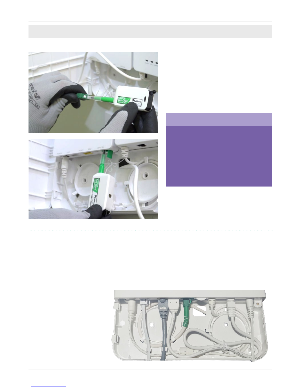
Remove the cap from the green bre
connector and use the One Click cleaner to
clean both the connector and the optical
port on the ONT. Once cleaned plug into
the Optical port on the ONT. Care must be
taken at this stage not to contaminate the
end of the bre connector to avoid any dirt
from inhibiting the data signal.
Open the green ap on the Optical port and
insert the bre cable. The cable is designed
to t only one way, so ensure the raised
nodule is facing the wall when inserting.
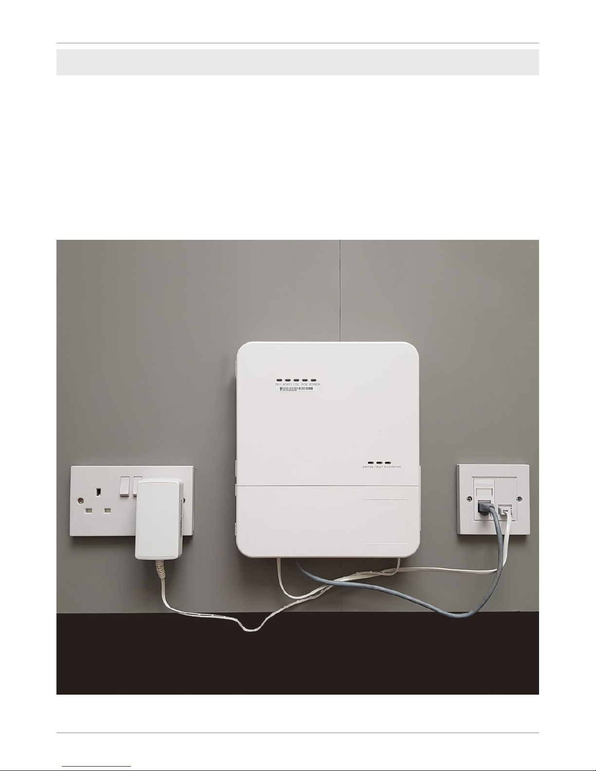
• Connect the alarm lead between the RJ45 socket on the BBU and the BBU port on the ONT.
• Connect the ethernet cable to the PORT 1 port on the ONT. The other end of this cable will be
connected to the CP router once ordered.
• Connect the telephone cable to the TEL 1 port on the ONT and plug into the Slave socket on the
wall (this cable is a separate item and will be provided by your FBC).
• Connect the mains
adaptor to the BBU
and plug into the mains
socket.
• You can see the nal
layout and cable
connections here,
ensure the cable lengths
are correctly positioned
within the enclosure
before continuing.
Developer self-install
Fujikura are our chosen producer of
bre cleaners. The One Click cleaner
shown here can be found at the
following link:
www.fujikura.co.uk/products/bre-
and-optical-devices/connectivityand-cleaning/one-click-cleaners/
Please note
Page 13
13
Developer self-install
• Once plot is complete contact your Openreach FBC
as each plot is ready for connection (i.e. front door
on; power on, ONT area decorated).
• Your Openreach FBC will then raise a job with the
Openreach teams to commission the plot(s).
DSI next steps
How to build a fibre network - version 7.1
Page 14
14
Openreach: Developer Guide
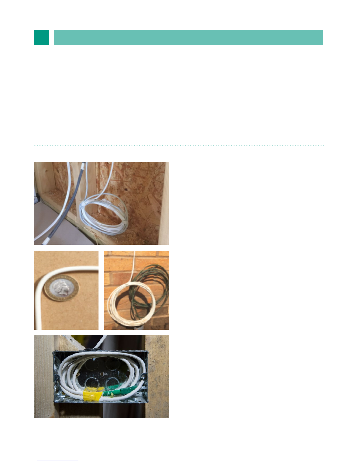
For Single Dwelling Units a pre-connectorised
cable will be available in different lengths
(5m, 20m, 30m, 50m and 100m) and will come in
individual bags that can be ordered via the FBC.
A minimum length of 2m of excess cable will be
left coiled externally for ease of installation.
Once the pre-connectorised cable is
installed then Openreach (or their third party)
will visit to terminate the pre-connectorised
cable at the external CSP location back to the
serving Splitter location(s) and then commission
the plot.
Single dwelling units
Run the pre-connectorised cable from
agreed ONT position back to external
Customer Splicing Point (CSP).
The bend radius of cable must meet
all necessary installation requirements
i.e. no 90 degree bends.
Coil 1m of pre-connectorised cable
into the empty double back box, taking
care not to damage the connectorised
end and t blanking plate to help
protect bre.
Ensure the green caps on the end of the
connectorised internal bre cable are
kept on during construction to avoid
damage to the bre cable.
Installation of pre-connectorised
cable at rst x (Internal Work)
Step 1
Step 2
Cabling and ONT positioning
4
Page 15
15
Complying with
Building regulations
Even where you are not working with
Openreach or another infrastructure
company to provide a functioning
broadband and phone infrastructure
to the home the Part R regulations
require the provision of duct in the
default position discussed below so
that infrastructure can be installed
in the future.
ONT in the
default position
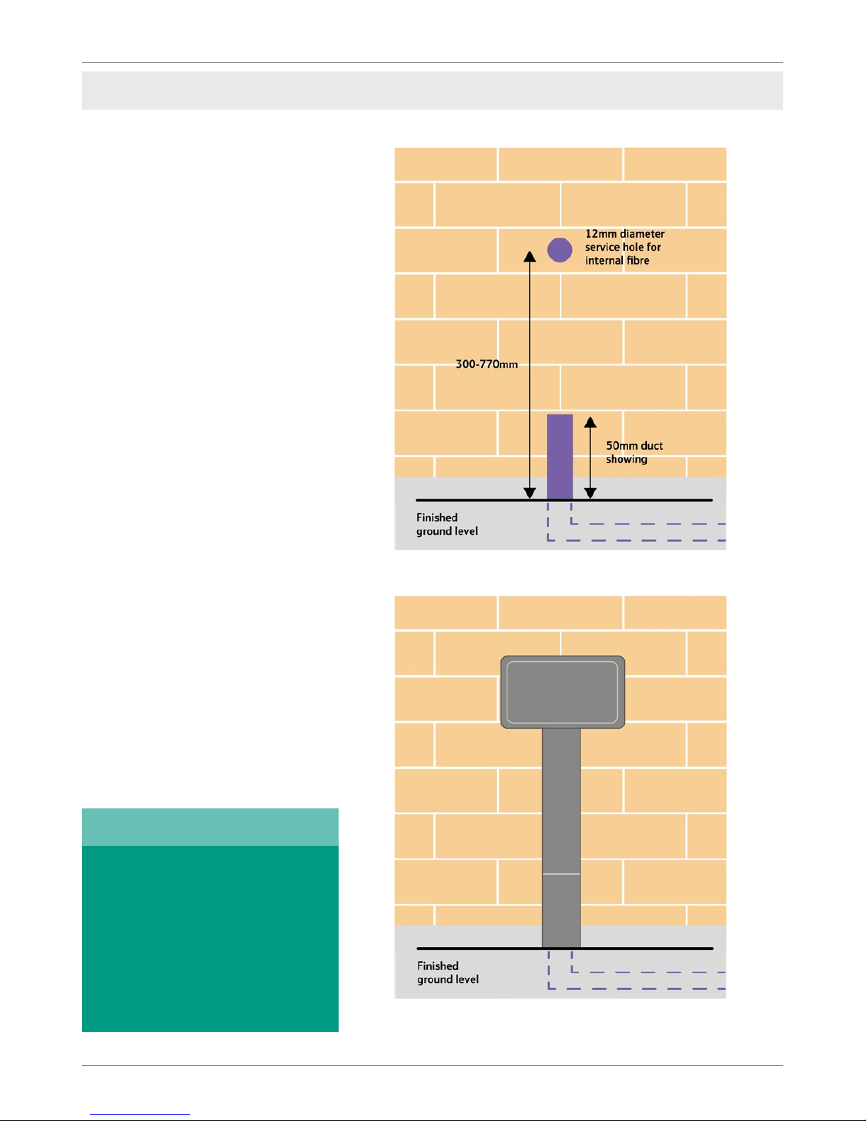
When the ONT is to be tted in the
default position on an internal wall
directly opposite the entry position
of the service access hole adjacent to
the external duct location, external
capping will be tted on completion.
To keep things tidy, make sure that
the service access hole is drilled in line
with the duct and in keeping with the
dimensions shown below.
The service will be sealed with a
grommet or mastic before tting
the CSP.
All internal wires and
sockets beyond the Optical
Network Terminal (ONT)
are the responsibility of the
developer/future home owner.
Any faults or defects resulting
in an Openreach visit may
incur a charge.
Please note
External presentation by developer
External capping tted by Openreach
Cabling and ONT positioning
How to build a fibre network - version 7.1
Page 16
16
Openreach: Developer Guide
Cabling and ONT positioning
Wherever possible, the duct shall be positioned
on the opposite side of the wall to where the ONT
will be installed, removing the need to run internal
bre cables. However, there are cases where the
kit will need to be installed away from the external
lead in and your FBC will be able to advise.
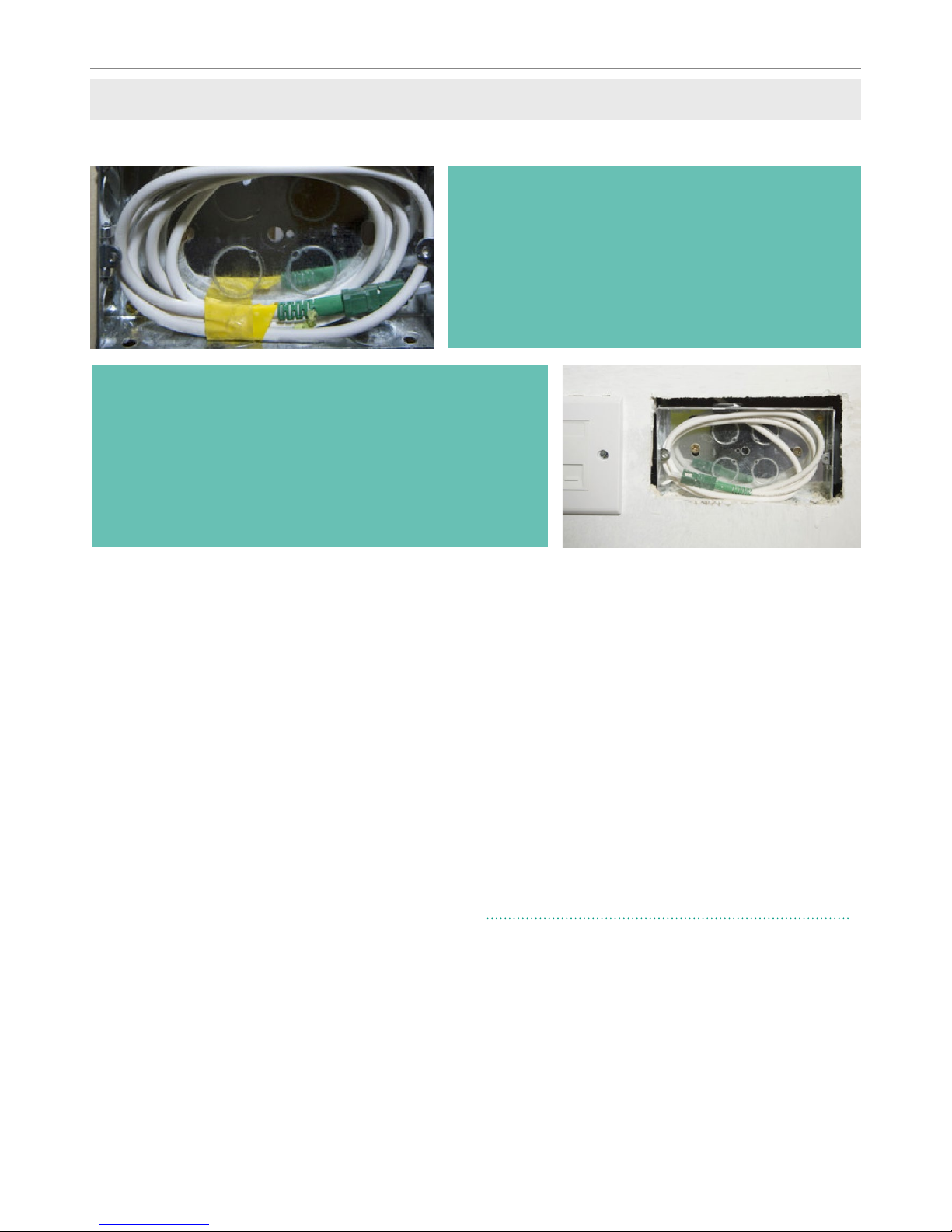
When Openreach is to install the Openreach ONT, battery
backup and external customer splice point, two metres of
cable is required at external end and 1m (or 2m for nonconnectorised cable) at the internal point of the installation.
It shall be left coiled and housed/protected within a
ush mounted double back box and faceplate ready for
Openreach provision of ONT and BB.
ONT installed inside the house (non-default position)
When the ONT is to be tted in a non-default
position i.e. not directly behind the external
CSP, such as in a utility cupboard, the above
guidelines shall be followed to provide entry of
the cable into the home.
What will be different will be the length of cable
that will run from the entry point into the building
to the Openreach ONT. In this case you have
the responsibility of running the connectorised
internal bre cable required inside the house in
such a way that it is undamaged and complies
with building regulations for the installation of
telecommunications infrastructure cabling.
The same rules apply to the running of bre
cable internally that are specied in the section
on exterior ducting. For example, the installation
of the bre cable in protective conduit and the
absence of a bend more than 90°.
Once installed the ONT and BBU need to
be kept powered on.
If this option is followed but the cable is found
to be damaged once in situ, either during
installation, damage sustained by construction
work inside the property, or damage subsequent
to the home owner occupying the property,
then unless you at your expense opt to replace
the damaged bre cable during commissioning
of the property, then Openreach will install
the equipment in the default location within
the home using surface mounted cables and
charge accordingly.
The developer must run the connectorised
internal bre cable in a continuous length and it
must remain free from any damage that could
reduce the lifespan of the cable.
Interconnecting voice lead (Item Code
077004) will be provided free of charge
by Openreach. It provides connectivity
from the ONT to a co-located voice
socket/patch panel. On installation
it becomes the property of the home
owner. Alternatively, the developer may
choose to hardwire directly into a voice
socket using a 431A Plug.
Page 17

17
Cabling and ONT positioning
When Openreach is to install the Openreach ONT,
battery backup and external customer splice point,
two metres of cable is required at external end of
the installation and 1m internally.
It shall be left coiled and housed/protected within
a ush mounted double back box and faceplate
(or could be a brushed faceplate if preferred)
ready for Openreach provision of external CSP
and ONT nearby.
When the developer is installing the Openreach ONT
and battery backup 2m of cable is required at the
external Splice Point and 1m at the ONT location.
Ensuring re safety with internal cabling
Once ductwork and cable has been run from communications
room to splitter – contact FBC to gain conrmation that all
cables are run correctly.
FBC will then raise a job with the Openreach Internal teams to
commission the splitter(s). Once commissioning is complete
contact FBC as each plot is ready for connection (front door
on power on, ONT location is decorated).
FBC will then raise a job with the Openreach internal teams
to commission the plot(s).
Multiple Dwelling Unit (external)
• Fit all external duct from the site connection
point to the building entry position.
• Fit all tray work from the building entry position
to and up the risers to the internal splitter
position(s).
• Run the bre cable from the splitter location to
(and in) the riser to the communications room.
• Coil a minimum of 2m in the communications
room.
• Coil a minimum of 2m at internal splitter
position.
• Ensuring bend radius of cable must meet all
necessary installation requirements i.e. no 90
degree bends (as per current copper process).
• If there is a comms room it has to be within
2m at point of entry.
• If the risers are away from the point of entry
but is fed through a vented car park then the
external cable can be fed on tray work.
• If the risers are away from point of entry and is
fed through a non-vented car park then an area
needs to be allowed within 2m of point of entry
to change from external to internal cable.
Multiple Dwelling Unit – Next Steps
• Once ductwork and cable has been run from
communications room to splitter – contact
FBC to gain conrmation that all cables are
run correctly.
• FBC will then raise a job with the Openreach
Internal teams to commission the splitter(s).
• Once commissioning is complete contact
FBC as each plot is ready for connection
(front door on power on, ONT location is
decorated).
• FBC will then raise a job with the Openreach
internal teams to commission the plot(s).
Fire stopping
compartment
penetrations
All holes drilled through oors and
re compartment walls must be
re proofed using correct materials
to prevent the spread of smoke
in the event of a re. Openreach
can provide these materials
in either cartridge (similar to
silicone sealant) or putty form.
How to build a fibre network - version 7.1
Page 18

18
Openreach: Developer Guide
Cabling and ONT positioning
Issues with home wiring
• Connectorised bre cable too short,
cut or damaged.
• Defective or damaged home wiring
creating a fault on the line.
• Extension sockets not connected to
Openreach ONT.
• Bending radii exceeded causing reduced
levels of service due to bre being broken
or the bend was too tight.
• Incorrect cable type or wiring
conguration
Impact on delivery
• Inability for Openreach to provide service
and developer requirement to re-provide
connectorised bre cable.
• Poor user experience for home purchaser
with possibility of Openreach charges if
called upon to rectify.
• Slower data download speeds
experienced.
• Limit duct runs to a depth of 350mm on
footway, 450mm on soft ground or 600mm
if shared carriageway surface at house end.
• The Openreach duct shall be no greater than
15mm from the nished wall surface.
• The duct shall protrude no more 50mm from
the nished ground level.
• A draw rope must be installed between the
joint box and the duct at the property wall.
• The duct opening must be covered,
preventing the ingress of debris.
• Ducting from property to the footway boxes
shall be laid 4-6 weeks before the plots are
handed over.
Fixing cables securely
If you’re running any cables through a re protected
area like a re escape route, escape staircase or
walkway, the cable must be adequately secured
using non-combustible xings. Wiring regulations
must be followed, ensuring that wiring systems
in escape routes are supported in such a way that
they will not be liable to premature collapse in
the event of re. This applies to all cabling and
not just electrical cables e.g. alarm, telecoms and
control wiring. From January 2019 this will apply
throughout the installation as the 18th Edition
wiring regulations come into force.
Typical issues with duct
presentation
• Duct not cut to the appropriate height
from the nished ground level.
• Duct installed too shallow.
• Duct protruding too far from the nished
wall surface.
• Duct not lining up with internal bre
cable lead in.
Impact on delivery of issues
• Delay in completion – Openreach may refuse
to cable if we can’t guarantee adequate
protection.
• The capping and covers would look unsightly.
• Failure to provide conduit can prevent a cable
from being installed.
• Customers may not be able to place orders
and remedial work may incur additional costs.
Page 19
19
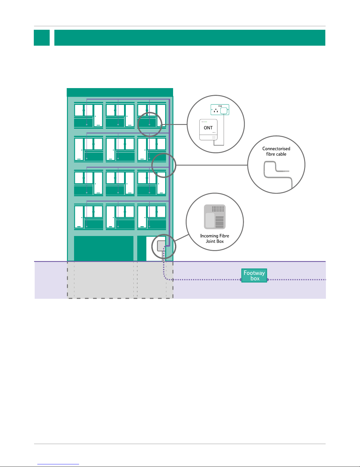
Small MDUs (12 or less units)
Openreach will create a bre layout based on
your Mechanical & Electrical (M&E) drawings
(on larger MDUs) of the MDU. The design
will calculate the stores required to build
the network.
Your FBC is on hand to guide you through the
ordering process to make sure the equipment is
available when you need it.
The incoming Duct 54zv and bre cable will
terminate in the communications intake room
or riser cupboard. This needs to be a secure and
safe location with access for installation and any
future maintenance visits.
Our bre box/splitter needs to be installed at
a minimum height of 200mm and a maximum
of 1500mm. Your FBC will agree the location
with you.
Connectorised internal bre cable needs to be
run from each plot to the bre DP location.
A minimum of 3m of coiled cable needs to be left
at the bre DP, with 1m left at the plot end.
A wayleave may be required from the building
owner prior to installing apparatus in common
areas. Remember you may need to order
copper, for example: for lift lines.
Multi Dwelling Units (MDUs)
5
How to build a fibre network - version 7.1
Page 20
20
Openreach: Developer Guide
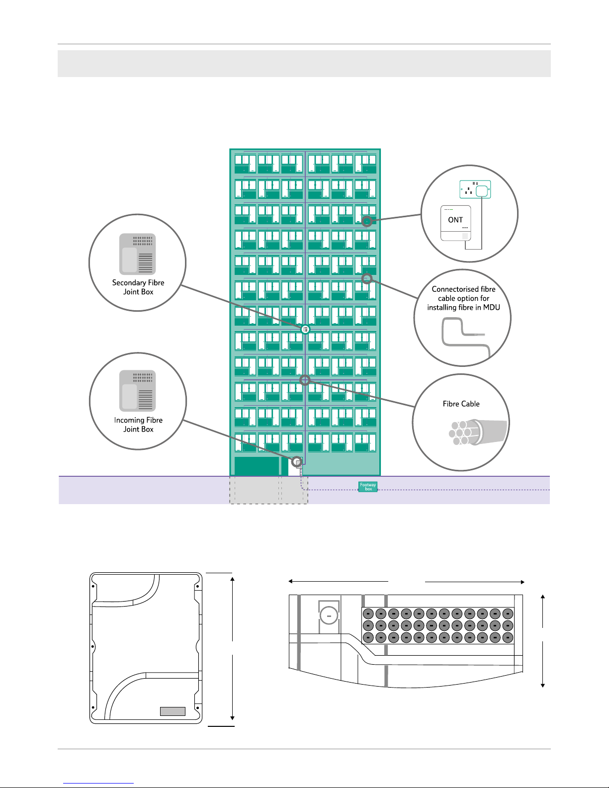
Large MDUs (more than 12 units)
For larger MDUs there may be a
requirement to install multiple bre
boxes/splitters.
405mm
These boxes/splitters will be connected with
Duct 54 and bre cable commonly housed
within the riser space.
330mm
120mm
Array of ports for internal bre cable
located at bottom of bre DP/splitter
Multi Dwelling Units (MDUs)
Page 21
21
Multi Dwelling Units (MDUs)
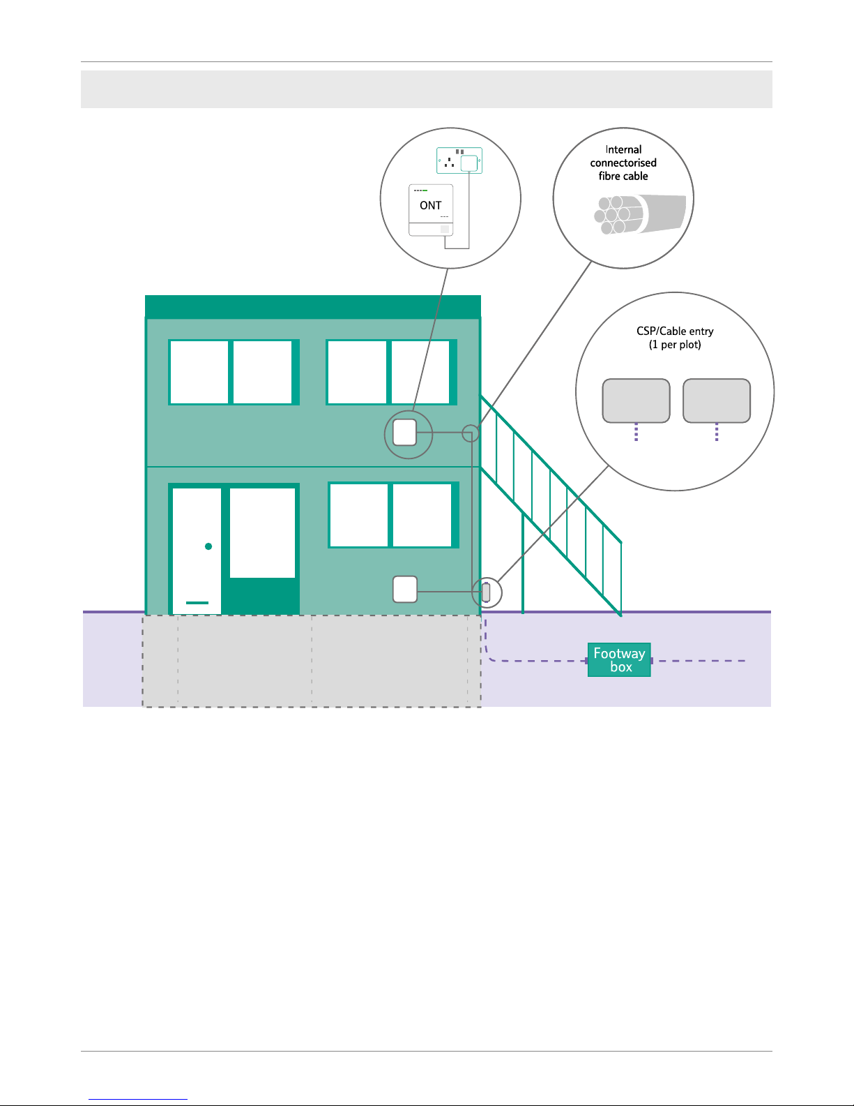
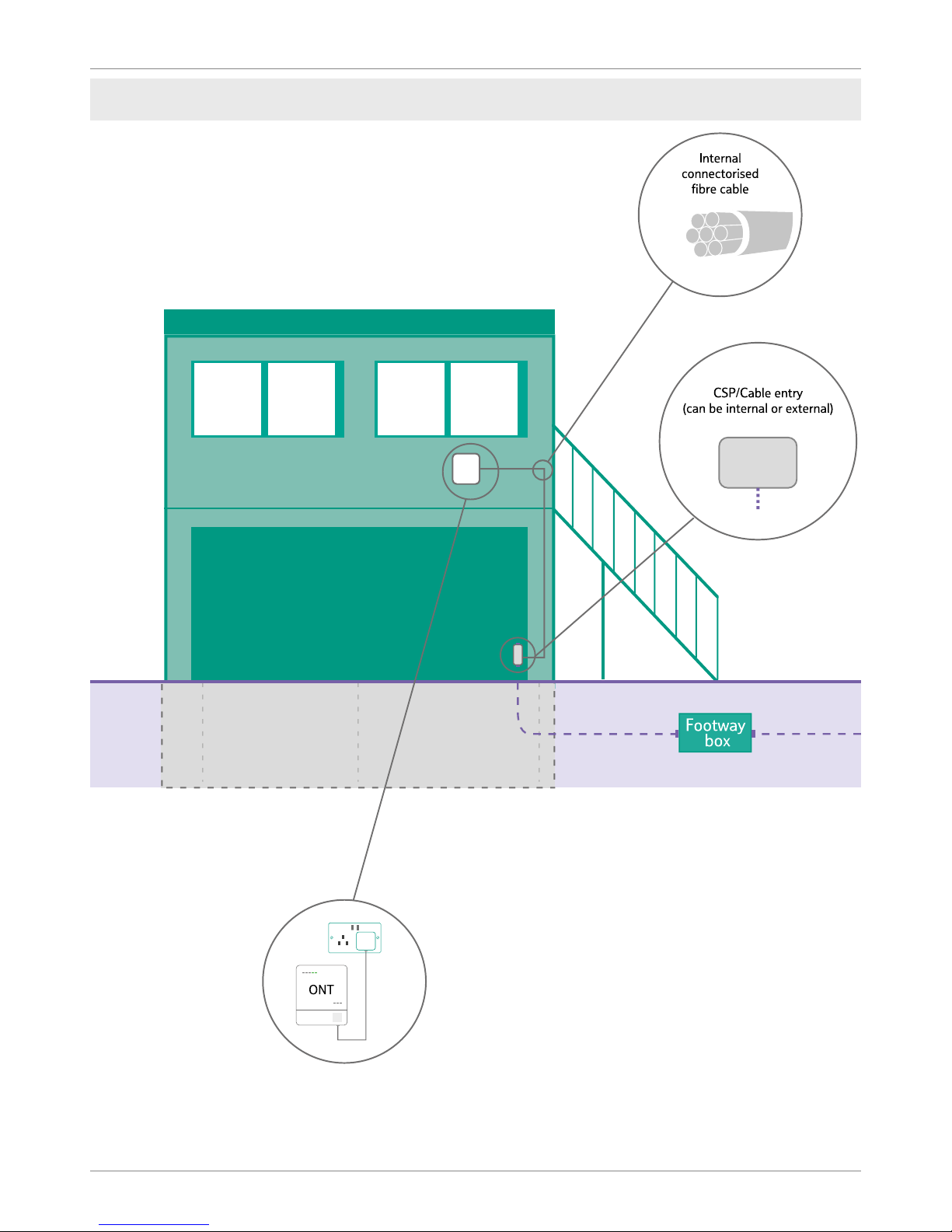
Maisonettes
How to build a fibre network - version 7.1
Page 22
22
Openreach: Developer Guide
Multi Dwelling Units (MDUs)
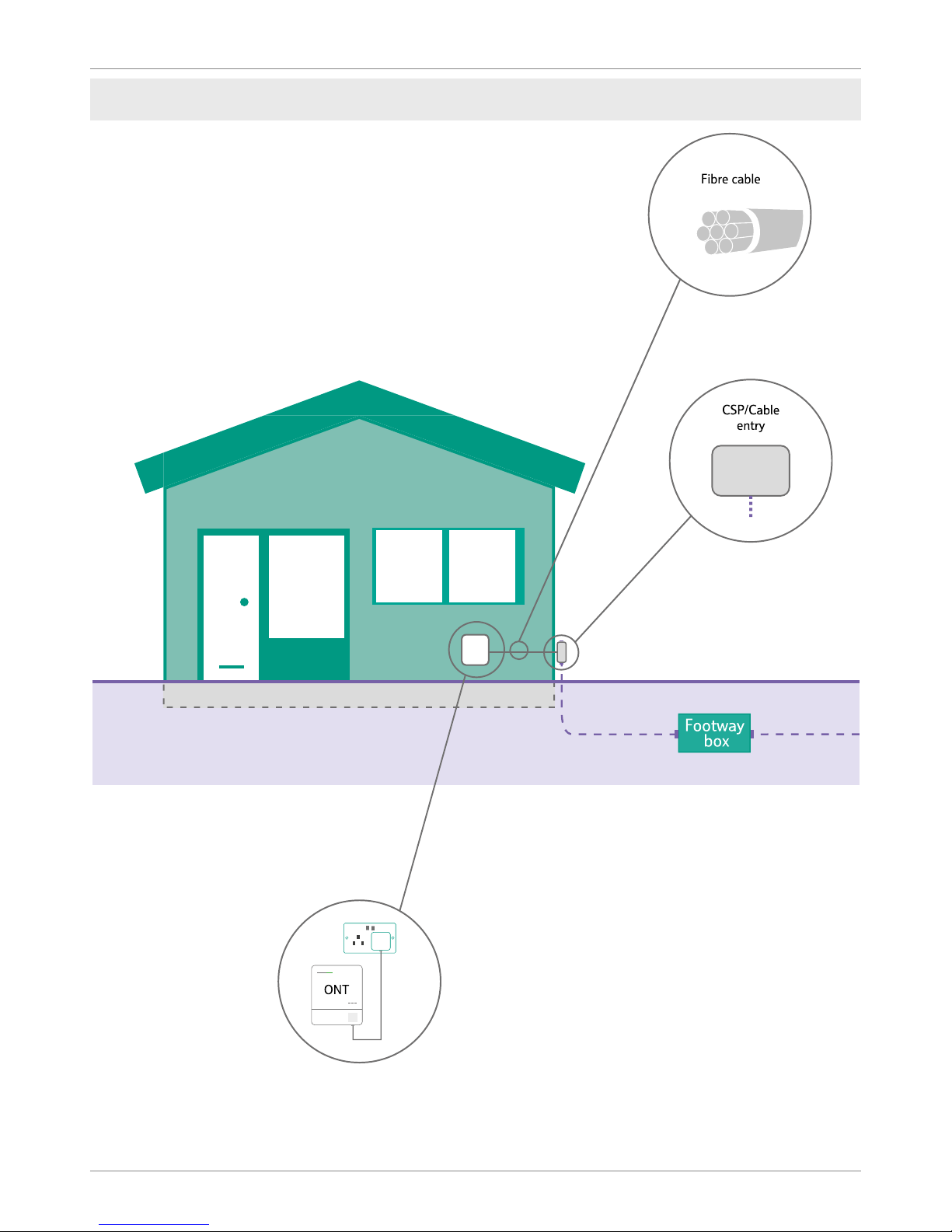
Flat over garage
Page 23
23
Multi Dwelling Units (MDUs)
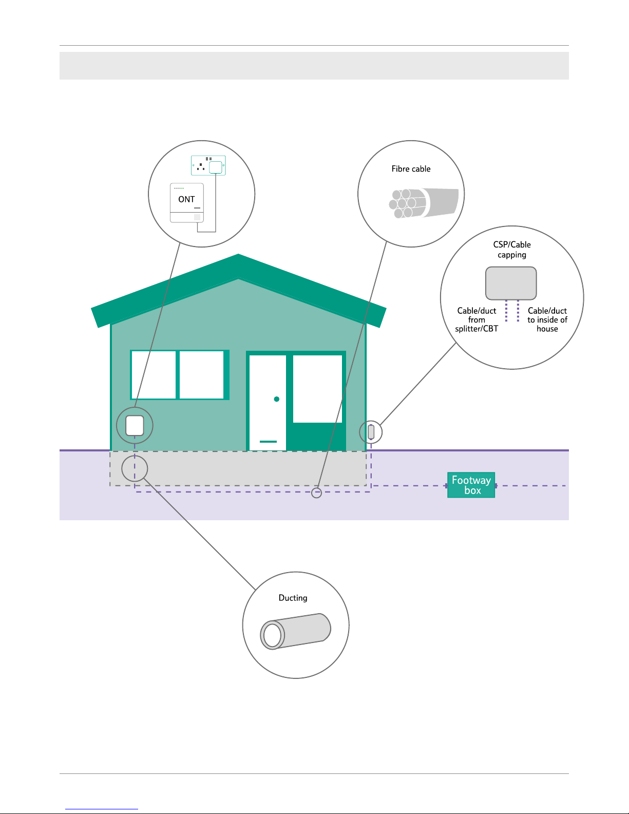
Chalets
How to build a fibre network - version 7.1
Page 24
24
Openreach: Developer Guide
Multi Dwelling Units (MDUs)
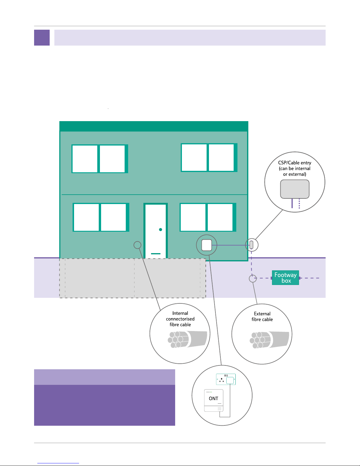
Modular/Passive homes
Page 25

25
Multi Dwelling Units (MDUs)
When Openreach is to install the ONT and battery
backup, 3m of cable is required at the splitter
location and 1m (2m if non-connectorised cable)
at the ONT end of the installation.
Each apartment will require a designated
connectorised internal bre cable run in a
continuous fault-free condition from the
designated ONT location within the apartment
to the splitter box within the riser.
At the splitter locations the cable should be
clearly marked with the apartment number and
left safely coiled within the riser.
• Install a ush mounted double back box at the
desired ONT location.
• Install the connectorised bre cable from this
point to the designated riser termination point.
• Ensure there is 1m of spare connectorised bre
cable protruding from the back box. (2m if nonconnectorised cable)
• Push some of the spare cable back into the
wall void and coil the remainder inside the
back box, taking care not to damage the
connectorised end.
• Install blanking plate or brushed face plate to
protect cable ready for provision of ONT nearby.
Option where Openreach installs the equipment
Your FBC will advise of all cable marking/
labelling and will check for this when ‘calling
off’ the work.
IET wiring regulations shall be followed.
External cables can run to a maximum of
2m from the internal building entry point.
From this point onwards, all cables must meet
current re regulations. The alternative is to
house all cables in metallic trunking.
Internal bre cable must not be bent beyond
its minimum radius. If it has been damaged
or there is evidence of kinking it shall be
discarded. Your FBC will advise on replacement
of the cable.
Care shall be taken to avoid stretching cable/
tubes through installation. If cables are
damaged this way you will be required to
replace them.
Bends in bre cable shall be kept to a minimum and
the installation of trunking, cable trays/grids shall
not compromise the bending radii.
Fibre cable containing no metal parts can be run on
shared trays.
Plate cable xings with cable ties must be used to x
bre cable direct to walls to avoid it being damaged.
Under no circumstances shall cable or tubing be
secured or supported to the suspended ceiling
hangers or under oor support legs.
It is the developer’s responsibility to provide
re stopping on completion of the cable/
tubing installation.
Openreach networks must not interfere with or
be interfered with by other services within the
riser or any other shared space. e.g.
• Un-insulated hot water pipes.
• Unscreened mains cables.
• Fluorescent lighting.
• Heavy duty switch gear.
A wayleave may be required from the
building owner prior to installing apparatus
in common areas.
Remember you may need to order copper lines
for commercial properties, for example lift lines.
How to build a fibre network - version 7.1
Page 26
26
Openreach: Developer Guide
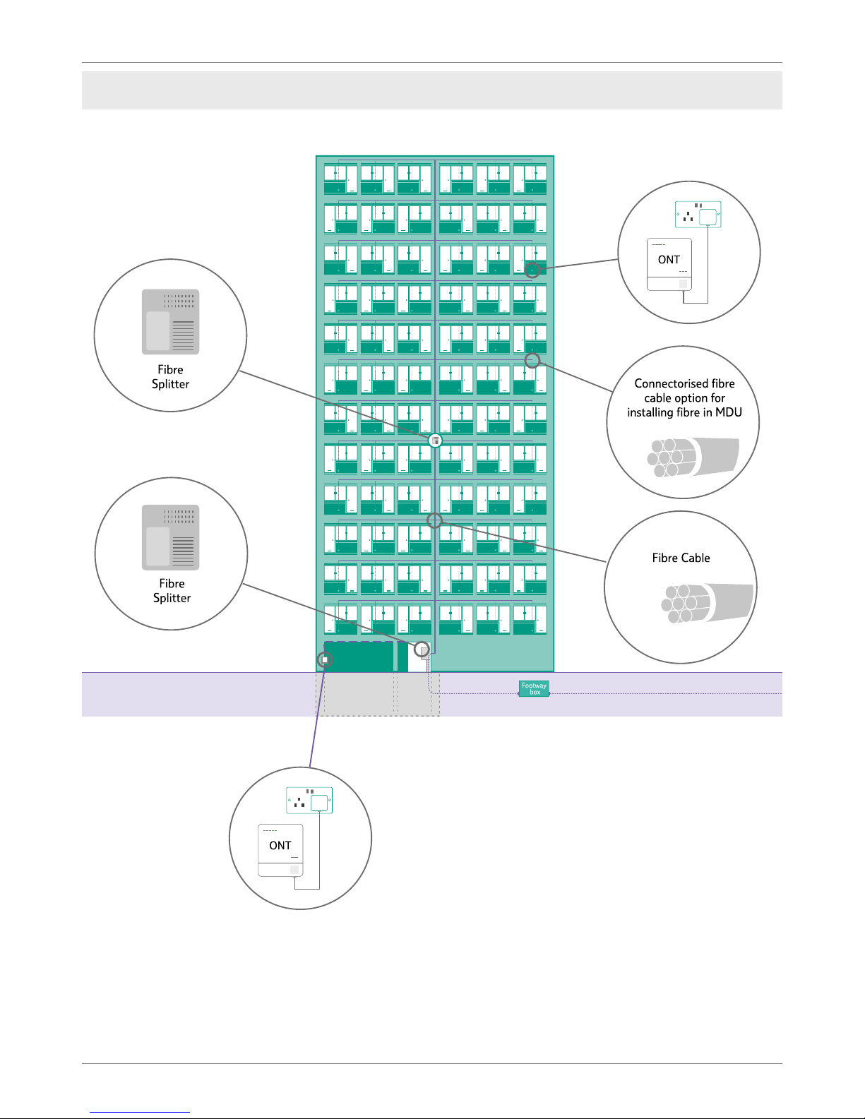
Small or Medium Enterprise (SME) unit on a
residential development
Commercial units
6
The ONT position within the building is
to be agreed between the FBC and the
developer on site.
Please note
Page 27
27
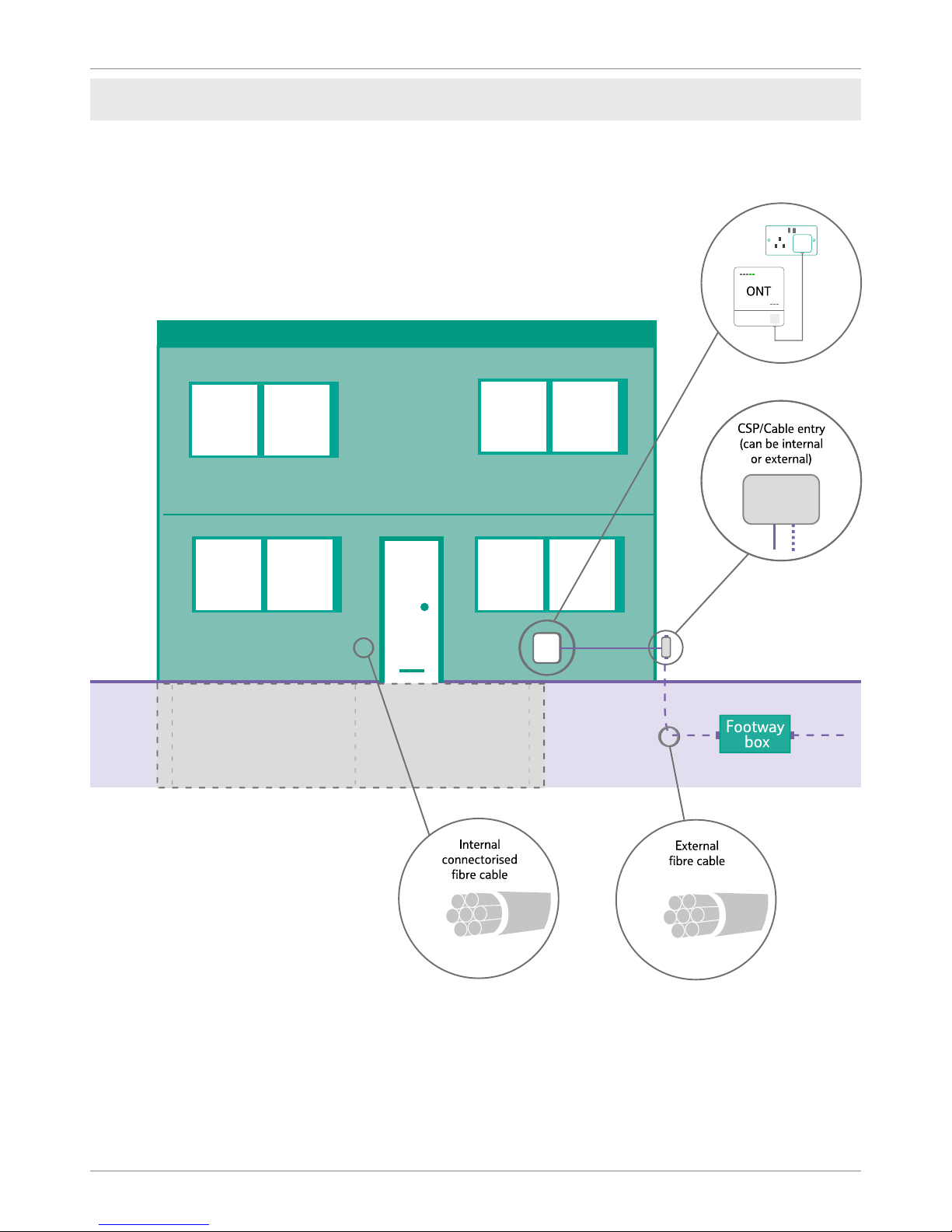
Commercial units
SME within
an MDU
How to build a fibre network - version 7.1
Page 28
28
Openreach: Developer Guide
Commercial units
Commercial unit within a commercial only site
Page 29
29
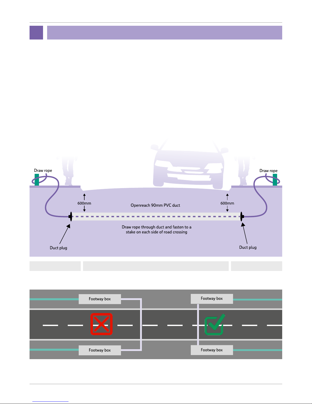
Where our duct crosses a carriageway,
adjoining kerbs must be temporarily marked
to note positions.
Openreach duct shall be laid on an outer edge
of the service trench to enable box building. A
draw rope shall be inserted through the duct and
secured to the marker posts at both ends of the
crossing.The appropriate Plug Duct 4B socket
end and 4C Spigot shall be tted.
Duct laid beneath a carriageway crossing must
be 600mm depth from the cover of the nal
surface levels and, for engineering reasons
(National Joint Utilities Group NJUG), separated
from other services laid in parallel by 600mm
(to permit us to install underground joint boxes
without the need for bends).
Carriageway Road Crossings
Footpath Carriageway Footpath
Duct laying
7
How to build a fibre network - version 7.1
Page 30

30
Openreach: Developer Guide
Ducting to the building
Duct to the premises/building must be laid at
a minimum depth of 350mm and be as straight
as possible.
The latest information on the positioning
of utilities, mains and plant can be
obtained from the National Joint Utilities
Group: www.njug.org.uk
Please note
Ducting general principles
• All runs shall be laid as straight as possible.
If needed, you can carefully bend the
ducts or use pre-formed bends supplied by
Openreach.
• There shall be no more than one pre-formed
90° bend in any single run of duct.
• Pre-formed 90° bends shall not be installed in
any duct linking two joint boxes.
• Footpath or service strip ducting must be laid
at 350mm depth of cover.
• All space alongside the duct must be
backlled with granular ll to a minimum
thickness of 75mm.
• For all Single Dwelling Units (SDU) duct
must be terminated on the external surface
of the property.
• The duct termination point shall be in a
location that will allow unrestricted access for
any future maintenance activity.
• All ducts must be provided with a draw rope
after installation, unless it’s agreed locally to
substitute the draw rope with a cable.
• Please notify your FBC when the duct has
been laid and is ready for inspection.
Commercial unit ducting
• 90mm duct can be laid either externally or
internally to the building, with 45 degree
angled bend.
• If internally then the duct should be sealed
once cabling is complete – the FBC will
provide this as a stores item.
• The termination point on a large
commercial unit within a commercial only
site should be located within 10m of the
entry point.
Duct laying
Page 31
31
Duct laying
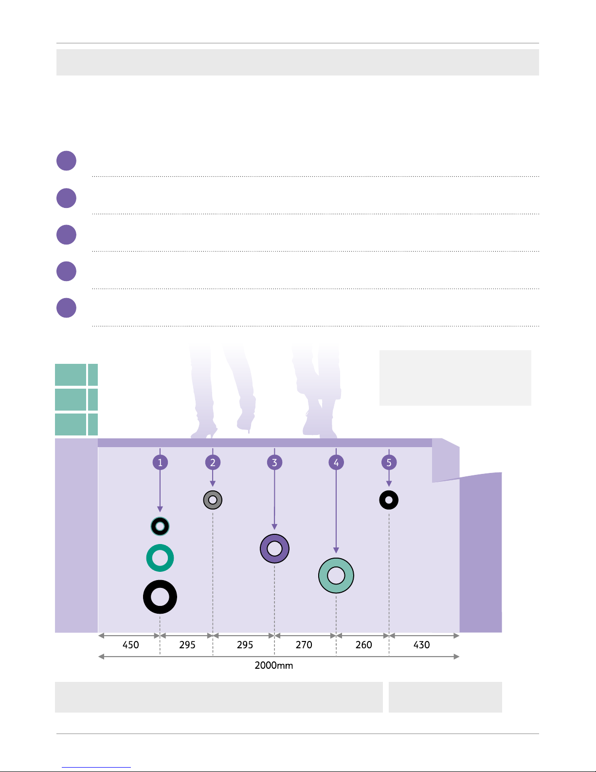
Recommend depth
of utility apparatus
1
2
3
4
5
Footpath Carriageway
Arrangement of mains services
Electricity / HV 450 to 1200mm / LV 450mm
Cable TV and Communications / 250 to 350mm
Gas 600mm
Water 750mm
Telecommunications 350mm
How to build a fibre network - version 7.1
Page 32

32
Openreach: Developer Guide
Duct laying
Openreach has an extensive underground
network that can be located inside / on the
perimeter of a site. This network is vulnerable
to excavation related damage unless appropriate
precautions are taken. The precautions for
avoiding damage to an underground utility plant
are contained within the Health & Safety Guide
no. 47: “Avoiding danger from underground
services”. This document stresses the need for
the availability of utility plans on site and the
use of safe digging practices.
Available here:
www.hse.gov.uk/pubns/books/hsg47.htm
Typical issues with carriageway
road crossings
• Insufcient depth.
• Proximity to other services.
Impact of issues
You will have to renew duct and this
may delay any rst occupation date or
subsequent occupation dates.
Damage to the Openreach network by a third
party can be expensive for that party to repair.
By working together, we want to make sure you
avoid the repair and associated cost which can
consist of one or more of the following:
• Direct Cost – the cost of repair.
• Operational Cost – delays associated
with repair.
• Social Cost – loss of service to emergency
services/ centres or the vulnerable in society.
Avoiding damage to the Openreach underground network
To obtain a more precise location of Openreach
infrastructure (either within your site or the adjoining land)
and avoid costly damage, contact:
Click Before You Dig
email: [email protected]
Utilisation of the Openreach “Click Before You Dig”
free service has a proven record of minimising the potential
for damage and cost.
If you need to move or consult on existing
Openreach equipment, contact us on
0800 783 2023 or complete the online webform at
www.ournetwork.openreach.co.uk/help-and-support.aspx
Page 33
33
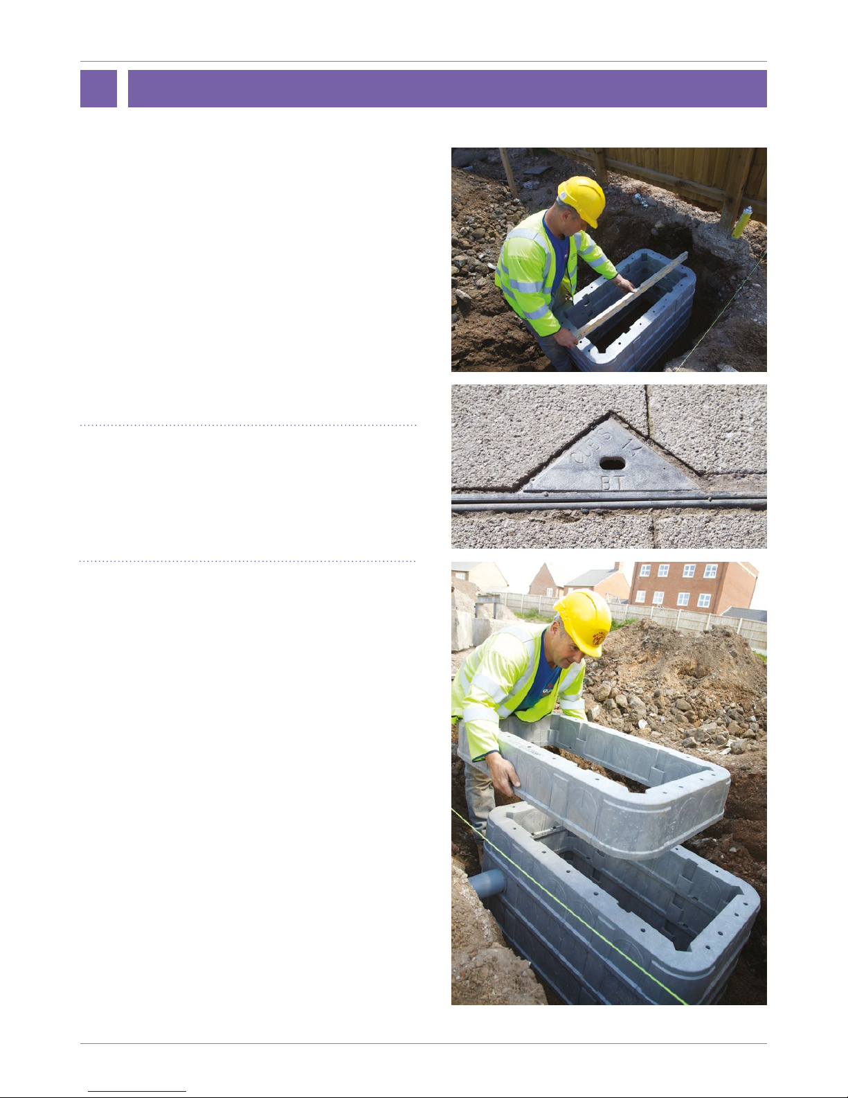
The optional approved pre-formed chamber
system Quadbox™ can be used to speed up
the installation process and bring signicant
productivity benets as there is no need for
specialist box building teams and concrete
backll to be used.
The Quadbox™ is not a free stores item from
Openreach, but can be purchased directly from
our approved supplier, Cubis Industries:
www.stakkabox-quad.com
Joint box modular footways 104 and 106
are the Openreach approved versions
(BT specication LN178).
Box furniture items slot into moulded pockets
within the chamber, eliminating the need to castin xings or drill on site. Duct entries are also easy
to achieve, using a standard hole saw mounted on
a cordless drill.
The lightweight high-strength system is
supplied as 150mm deep twin wall high-density
polyethylene (HDPE) rings to provide maximum
exibility and strength which are simply stacked
on a prepared base and backlled with suitable
as-dug or Type 1 material. See the suppliers
Installation Guide Which comes with your box.
If purchasing a pre-formed chamber you are
required to purchase the associated furniture.
Modular jointing chambers – Quadbox
TM
8
How to build a fibre network - version 7.1
Page 34
34
Openreach: Developer Guide
Furniture
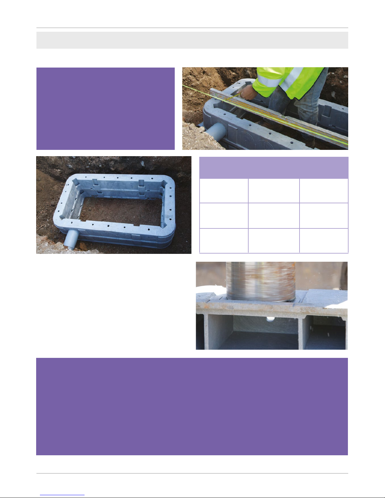
Cable brackets and steps (where
required) are supplied in a bagged kit
and easily slot into purpose designed
pockets in the chamber. The brackets
and steps drop into preformed slots.
Available Size Range
Product Code Clear opening
Depth Per
Section
JMF104 915X445mm 150mm
JMF106 1310X610mm 150mm
Duct entries
Duct entries can be cut as and where required
using a hole saw mounted on a cordless drill.
The chambers incorporate guides which identify
drilling points to ensure correct duct spacing.
A maximum of 4 duct entries can be made into
a single wall of the Quadbox™.
Quadbox points of note
As with brick built chambers, care should be taken to make sure:
• The box is set at the correct depth and the base/ plinth is installed correctly.
• The side wall is not damaged/misshapen due to over compaction.
• The frame is level with the surface and a core drill is used for cutting duct entries.
• The developer is required to purchase the required wall bearers
Modular jointing chambers – Quadbox
TM
Page 35

35
Joint box designs and specications may vary depending on the duct layout and whether
multi-way ducts or major road crossings need to be incorporated into the network design.
Full technical drawings and specications are available at www.openreach.co.uk/propertydevelopments
Footway (JBF104/106)
Materials
• Bricks: BS EN771-1. Stretcher Bond.
• Cement: BS EN197-1:2000 ordinary mix.
Three parts sand to one part cement.
Specications
• Base: 150mm concrete, clean and level.
• Brickwork: Keyed in at the corners
and pointed.
• Frame and cover: Set on a mortar bed and
fitted squarely to the box structure. You can
purchase lifting keys for the covers from TW
Engineering Co Ltd at www.twtools.co.uk (tel:
0115 932 3223).
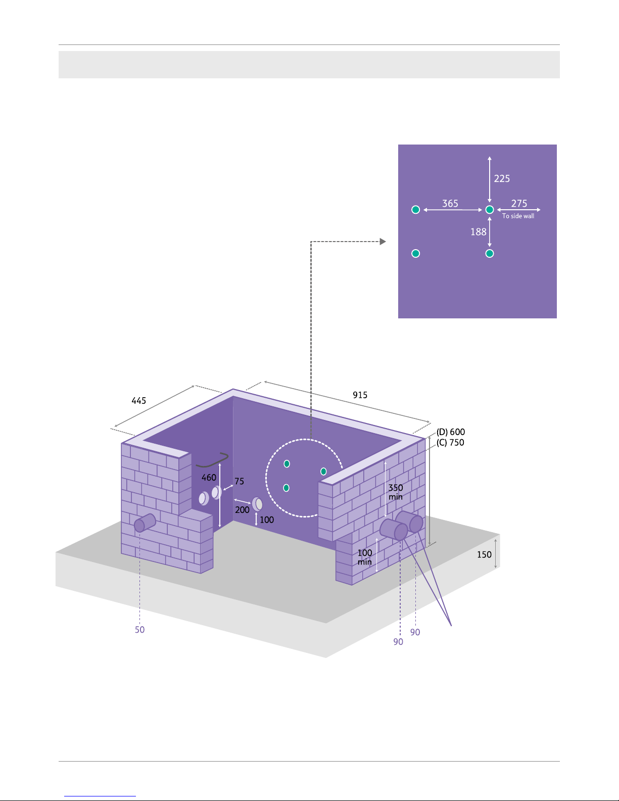
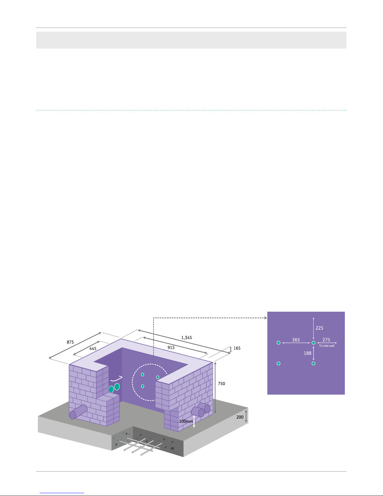
• Duct entries: Must not enter through corners
and be no less than 75mm from the side wall.
They shall enter wall at a minimum depth of
350mm from the top of the frame, cut flush
and clear the base by a minimum of 100mm.
• Bolts: Must be fitted in each box to allow
ironwork to be installed by the developer.
• Step(s): One step is required in all boxes
deeper than 700mm.
• JBF104(C): 915mm(L) x 445mm(W) x
600mm(D).
• JBF104(D): 915mm(L) x 445mm(W) x
600mm(D) the minimum depth for boxes
either side of road crossings.
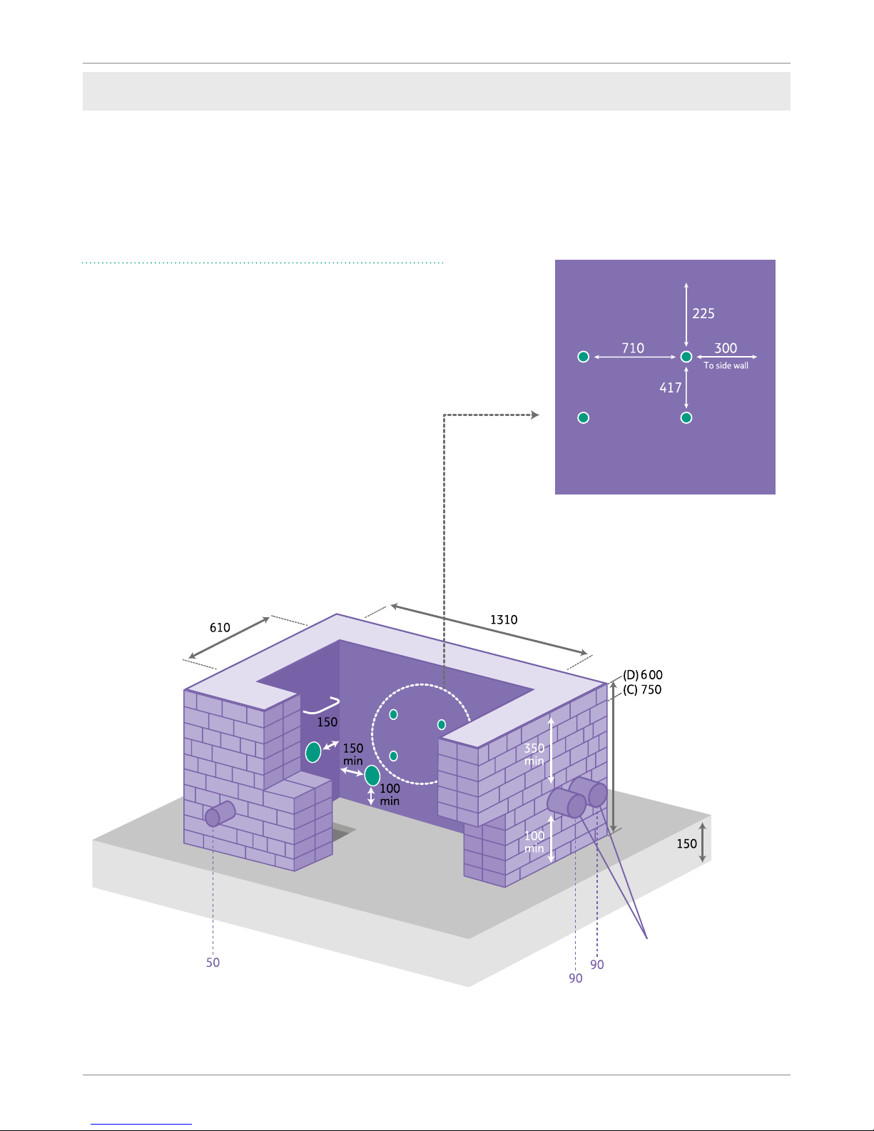
• JBF106(C): 1310mm(L) x 610(W) x 600(D).
• JBF106(D): 1310mm(L) x 610(W) x 600(D)
the minimum depth for boxes either side of
road crossings.
• All backll material to be class 6N type.
• Workmanship, materials and method of
construction are to comply with all current
relevant contract documents, British
Standards and codes of practice for the
construction industry.
• Concrete to be grade C32/40 with a water
cement ratio 0.4 minimum. Cement content
380kg/m3. Aggregate maximum size 20mm.
All in accordance with BS8500.
• All ducts shown are based on maximum
recommended values for Duct Type 54D.
• End ducts to be inline.
• Ducts to be positioned not less than 75mm
from a side wall.
• Mesh to be grade B500B or B500C
conforming to BS4483.
• Short lengths of Duct 54D 90mm to be used
on non-ducted routes. Appropriate duct to be
used on ducted routes.
• Where instructed to do so drill one set of
three holes using a 12mm masonry drill
bit to a depth of 80mm for future tting of
equipment mounting bracket.
• For details and specs on using corbelling visit
the link at the top of this page
At no time must minimum box depth be
compromised. Consult your FBC if the
minimum depth cannot be achieved.
Please note
Joint boxes, footways and frames & covers
9
How to build a fibre network - version 7.1
Page 36
36
Openreach: Developer Guide
Concrete
base
Bolts foundation for
wall bearer/brackets
Duct
Joint box footway 104
– the preferred option
Internal dimensions. Brickwork Stretcher Bond.
Dimensions in mm (not to scale).
Joint boxes, footways and frames & covers
Page 37
37
Concrete
base
Duct
Joint box footway 106
Internal dimensions. Brickwork Stretcher Bond.
Dimensions in mm (not to scale).
• Minimum depth for road crossing 900mm
• Sump to be tted in boxes deeper than 700mm
Bolts foundation for
wall bearer/brackets
Joint boxes, footways and frames & covers
How to build a fibre network - version 7.1
Page 38
38
Openreach: Developer Guide
Joint boxes, footways and frames & covers
Carriageway JBC4
Box design and specications may vary. This will be determined by the duct lay-out and whether
multi-way ducts or major road crossings need to be incorporated into the design.
Materials
• Bricks: BS EN771-1. English Bond.
• Cement: BS12 Portland Cement.
• Concrete: BS EN206 Grade 32/40 concrete.
• Mortar: BS5628, Part1 requirement for
mortar Table 1, Type (i).
Base
• Cement: BS12 Portland Cement.
• Concrete: 200mm concrete Grade 32/40,
reinforced with A393 grade mesh at
70mm cover.
Brickwork
• Bricks: BS EN771-1. English Bond.
• All brickwork to be keyed in at corners
and pointed.
• Brickwork to be ‘English Bond’ constructed
with a 10mm joint thickness of cement mortar.
Frame and cover
• Frame and Cover Carriageway no.4 to be
squarely set on a mortar bed Highway Agency
standards HA104.
Lifting keys
• Key Joint Box Lifter should be used to lift
the cover and can be purchased from TW
Engineering Co Ltd at www.twtools.co.uk
(tel: 0115 932 3223) or similar supplier of
your choosing.
Duct entries
• Duct to be cut ush to the internal box wall.
• Duct must not enter through corners and be
no less than 75mm from the side wall.
• Duct to enter wall no less than 600mm
from the top of the frame.
• Duct to be no less than 100mm from the
box base.
Bolts foundation for
wall bearer/brackets
Concrete
base
F
or use with carriageway no.4
frame and cover
A393 Mesh
950x950
Page 39
39
Joint boxes, footways and frames & covers
Frames and Covers
Cubis Industries is the only supplier of these
Openreach approved products
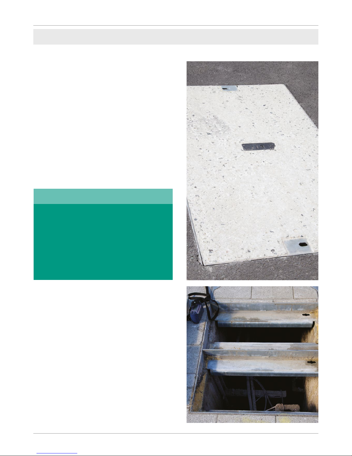
Only approved frames and covers shall be tted
on your site. They are identiable by the following
markings; ‘EN24 B125’ the British Standards
kitemark the Manufacturer Mark (SID), the year of
manufacture and the BT identier.
The ‘standard frames and covers’ are supplied
by Openreach. They consist of a galvanised steel
fabricated frame, tted with unlled galvanised
steel fabricated cover trays and cross-beams.
All covers can be tted to brick or concrete.
Where there’s evidence or high risk of
vehicles using the soft verge e.g. as an
undertaking area opposite a T-Junction,
a passing point on a narrow road or a
parking area, it will be necessary to install a
‘carriageway chamber, frame and cover’.
There is also an optional
‘recessed frame and cover’
Please note
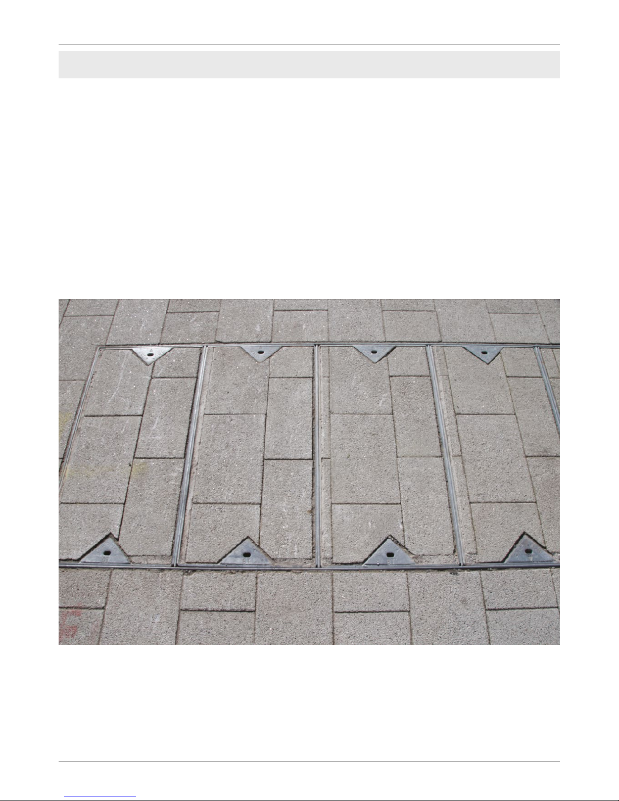
Recessed frames and covers
These can be purchased by the installer as an
option to the ‘standard frame and cover’.
Each cover tray has two key-hole ttings (in the
centre of the short side) one of which carries a BT
identity mark and the manufacturers’ three letter
identication ‘SID’. The other key-hole tting
displays EN124 and B125 together with the BSI
Kite mark certifying the covers to BS EN124: 1994.
Recessed frames and covers will accommodate
inll blocks to a maximum depth of 60mm.
If you’re planning to install frames and covers
that aren’t supplied by Openreach e.g. for block
paving, or you have any doubts about what frames
and covers to use, please speak to your FBC.
How to build a fibre network - version 7.1
Page 40
40
Openreach: Developer Guide
Joint boxes, footways and frames & covers
Installation
All frames and covers shall be levelled to the nal
running surface.
Where a box is located within a grass, soft or
unmade surfaces, the frame shall be surrounded
with a 100mm wide strip of minimum grade
C25/30 concrete, to the full depth of the frame,
nished level with the top edge of the frame and
the outside edge. It must be straight and parallel
to the frame.
Unapproved frames and covers
Unapproved frames and covers must not be
tted. Openreach will take any necessary action
against any developer who ts unapproved
frames and covers within the network, including
any potential claim for damages and costs, with
possible delayed Service On Demand (SOD)
payments.
If you’re unsure how to specify approved covers,
please contact your FBC.
Page 41

41
BBU
BSI
BT
CLI
CP
CSP
DP
FDP
FTTP
FBC
HDPE
IET
JBC (N)
JBF
LSZH
MDU
MJF
M&E
NJUG
NTE
NTP
ONT
PAS
PE
PVC
RFH
SID
SDU
SOD
UG
Openreach maintains that all
reasonable care and skill has been
used in the compilation of this
publication. However, Openreach
shall not be under any liability
for loss or damage (including
consequential loss) whatsoever or
howsoever arising as a result of
the use of this publication by the
reader, his servants, agents or any
third party.
In the event of a discrepancy
between the contents of this
document and the contract,
the terms and conditions shall
take precedence. This is a living
document and will be subject to
update and change. The information
within this document is provided
for information purposes only.
The Contract and Price List take
precedence.
Battery Backup Unit
British Standards Institute
British Telecommunications
Customer Lead In
Communications Provider
Customer Splice Point
Distribution Point
Fibre Distribution Point
Fibre to the Premises
Field Based Coordinator (formally New Site Representative)
High-Density Polyethylene
Institute of Engineering and Technology
Joint Box Carriageway New Sites
Joint Box Footway
Low Smoke Zero Halogen
Multiple Dwelling Unit
Product code designation for the Cubis Industries–StakkaBox/Quadbox
Mechanical & Electrical
National Joint Utilities Group
Network Terminating Equipment
Network Terminating Point
Optical Network Termination
Publically Available Specication
Polyethylene
Polyvinyl Chloride
Reduced Fire Hazard
Manufacturers three letter identication
Single Dwelling Units
Service on Demand
Under Ground
List of abbreviations and acronyms
10
How to build a fibre network - version 7.1
Page 42

42
Openreach: Developer Guide
This guidance is a practical aid for designers and site workers on what
to eliminate, avoid and consider when working on the Openreach
network on your site.
The advice is not exhaustive so speak to your Field Based
Co-Ordinator (FBC) if you need further information.
Red lists
Hazardous procedures, products and processes that should be eliminated
from the project where possible.
Distribution point (DP) location
• Placing DPs into voids or other enclosed spaces with inadequate ventilation
• Placing DPs adjacent to, or above, any fragile surface
• Placing DPs directly above, or adjacent to, water features / courses etc
• Locating DP at greater than 1.5 meters above nished oor level (without xed access
system incorporated into design)
Cabling routes and lead-ins
• Routing of cables where the cables are above head height within false ceiling systems
without a proper access system incorporated
• Routing of cables external to building requiring specialist access methods (scaffold,
mobile elevating work platform etc.)
• No internal ducting laid into Single Dwelling Units (SDUs)
Power systems
• Ensure all power installation meet relevant standards, and where DC supplies are planned
seek further advice about requirements for earthing of racks, power supply ratings etc. to
take account of future needs and growth
Aerial and antenna transmission / receiver systems
• Not mounted on building walls or other difcult to reach areas of a building
• Design of roof mounted services that require access (for maintenance and so on), without
provision for safe access (such as barriers) in particular access for aerials / antennas systems.
Health and safety advice
11
Page 43

43
Amber lists
Products, processes and procedures to be eliminated or reduced as
far as possible and only specied or allowed if unavoidable.
Including amber items would always lead to the provision of information to the
principal contractor or contractor where only one contractor has been appointed.
Distribution point (DP) location
• DP’s located into voids or enclosed spaces provided with ventilation systems built in
Cabling routes and lead-ins
• Routing of cables where the cables are above head height within false ceiling systems
• Routing of cables internally where access points require use of access equipment
(ladders, step-ladders or platform steps) to allow for pulling in of cables
Aerial and antenna transmission / receiver systems
• EMF exclusion zones adequately managed with xed barriers or partitioning systems.
Health and safety advice
How to build a fibre network - version 7.1
Page 44

44
Openreach: Developer Guide
Health and safety advice
Green lists
Products, processes and procedures to be positively encouraged.
• Adequate access for vehicles to minimise reversing requirements (one-way systems
and turning radii) in particular if specialist vehicles will need access (pole erection units,
MEWP vehicles etc.).
• Provision of adequate access and headroom for maintenance in communications rooms,
and adequate provision for replacing heavy components.
• Thoughtful location of mechanical and electrical equipment, such as telecoms
equipment, termination points, Wi-Fi transceivers etc. and so on to facilitate access,
and placed away from crowded areas.
• Lighting within communications rooms adequate for ne tasks (bre splicing, small
diameter copper wire terminations etc.)
• Provision of adequate air handling / conditioning and ventilation for the installed
equipment base within the communications room (and people having to access and
work within the area)
• Early installation of permanent means of access, and prefabricated access systems with
hand rails.
• Provision of edge protection at permanent works where there is a foreseeable risk of
falls after handover (consider radio antenna or aerials installations on roof spaces).
• Encourage the use of engineering controls to minimise the use of personal
protective equipment.
Page 45

45
Quality control checklist
12
To help make sure your site network is
built to a high quality standard, we’ve
produced a checklist for each phase of
the build.
Any subsequent changes to the site plan
after a checklist has been completed
must be communicated and agreed with
your FBC as soon as possible.
Any re-work as a result of an out of date
site plan could cause delivery delay and
incur you costs in time related charges.
The Site
Developer
Site Name
Post Code
Site Manager/
Developer
Agent Name
Telephone
Email
Site Address
Openreach New
Site Identity Ref
The Site Manager/Developer
Agent agrees to the quality
standards and conditions.
Signature:
Date:
If you have any questions about your development, please visit
www.openreach.co.uk/propertydevelopments or call us on 0800 783 2023
New Sites Ofce
FBC Name
Telephone
Email
Off-site Connection Location
First Occupation Date
Site Start Date
Openreach Contact
How to build a fibre network - version 7.1
Page 46

46
Openreach: Developer Guide
Quality control checklist
Base has been cast correctly Joint Box
Reinforced base cast correctly for
Joint Box Carriageway JBC (N).
Joint Box
Bearers and brackets tted. Steps
tted where appropriate.
Joint Box
Bolts tted and positioned correctly
during construction of boxes.
Joint Box
Joint Box constructed to correct
dimensions and installed at the
correct depth. Any deviations to plan
recorded and signed off.
Joint Box
All concrete/brickwork carried out
as per developer ‘How to’ guide
specication.
Joint Box
Cement and brick types used as
specied or exceptions agreed and
documented.
Joint Box
Frames and covers bedded and
correctly installed (if unmade
surface, Joint Box frame secured).
Joint Box
Joint Box constructed as planned,
positioned correctly and conforms
to drawings. Alternatives agreed
and documented.
Joint Box
Modular box installed and prepared
as per instructions.
Joint Box
Ducts properly trimmed and keyed
when set in walls.
External cable/Blown Fibre Tubing (BFT)
protected and sealed in Joint Box.
Joint Box
Joint Box
Item being audited Category
Yes No N/A
Checked and
Acceptable
Standard?
Comments
Page 47

47
Fibre cable and draw rope provided
in sound condition and correctly
jointed where applicable.
Duct
DuctCable/BFT left in planned location.
Correct rope/cables/tubing installed
as per Developer ‘How to’ guide.
Correct type of duct provided
and used.
Duct laid in required position, at
correct depth and installed in the
correct position in the Joint Box.
Duct properly trimmed and keyed
when set in walls.
Duct separation distance
maintained, or exception agreement
obtained and documented.
Ducts laid at minimum depth
(350mm), or exceptions agreed
and documented. (To be viewed in
footway where possible, if not check
via Joint Box).
Joint Box constructed as planned,
positioned correctly and conforms to
drawings. Alternatives agreed and
documented.
Temporary duct seals tted to
agreed standard.
Ducts positioned correctly on
external walls and in line with the
cable entry point.
Item being audited Category
Yes No N/A
Checked and
Acceptable
Standard?
Comments
Duct
Duct
Duct
Duct
Duct
Duct
Duct
Duct
Duct
Quality control checklist
How to build a fibre network - version 7.1
Page 48

48
Openreach: Developer Guide
Quality control checklist
Plot
Ducts positioned in line with the
cable entry point.
Plot
Customer cable entries correctly
positioned and provided.
External cable/BFT protected
and sealed.
Plot
Duct seal Plug 1A tted.
Plot
Back box installed at entry point.
Back box tted at a usable depth,
within close proximity to a double
240v outlet for FTTP services.
Plot
The property has been designed to
accommodate voice and data wiring
in a convenient place for home
owners to use FTTP services.
A permanent 240 volt supply is
required for FTTP. Developer has
been informed that no orders can
be made or taken via a Service
Provider until all installation works of
Openreach equipment into each plot
has been completed and tested.
Item being audited Category
Yes No N/A
Checked and
Acceptable
Standard?
Comments
Plot
Plot
Location of unit entry point suitable
for FTTP equipment.
Plot
Plot
Voice and data cabling provided
and terminated correctly for FTTP
services.
Plot
If FTTP self install development ONT,
BBU, all leads connected correctly
and plot commissioned.
Plot
If self install not completed and
Openreach completes all internal
work then SOD payment for self
install is not applied
Plot
Page 49

49
All tubes or cables presented
as per schematic diagram and
capped.
Multi
Dwelling Unit
Designated track ways/trays
supports in good working order with
separations maintained.
Connectorised bre cable installed
as per schematic in accordance with
Manufacturer’s specications and
IET wiring regulations. Cable labelled
and coiled safely within riser.
Connectorised bre cable installed
with 1m of spare length protruding
from the back box to enable jointing.
Back box tted in each unit at a
usable depth, within close proximity
to a double 240v outlet for FTTP
connectivity.
Location of unit entry suitable for
FTTP equipment.
If FTTP self install development ONT,
BBU, all leads connected correctly
and plot commissioned
If self install but Openreach
completed all internal work then
SOD payment for self install is
not applied.
Item being audited Category
Yes No N/A
Checked and
Acceptable
Standard?
Comments
Multi
Dwelling Unit
Multi
Dwelling Unit
Multi
Dwelling Unit
Multi
Dwelling Unit
Multi
Dwelling Unit
Multi
Dwelling Unit
Multi
Dwelling Unit
Quality control checklist
How to build a fibre network - version 7.1
Page 50

50
Openreach: Developer Guide
Notes
Page 51

bre
network
How to build a
Page 52

www.openreach.co.uk
The telecommunications services described in this publication are subject to availability and may be
modied from time to time. Products and services are provided subject to British Telecommunications plc’s
respective standard conditions of contract. Nothing in this publication forms any part of any contract.
Openreach and the Openreach logo are trademarks of British Telecommunications plc.
© British Telecommunications plc 2018.
Registered ofce: 81 Newgate Street, London EC1A 7AJ
Registered in England No: 1800000.
Produced by Openreach.
Designed by westhill.co.uk
PHME 77439
 Loading...