

Linebox NTE5C User instructions
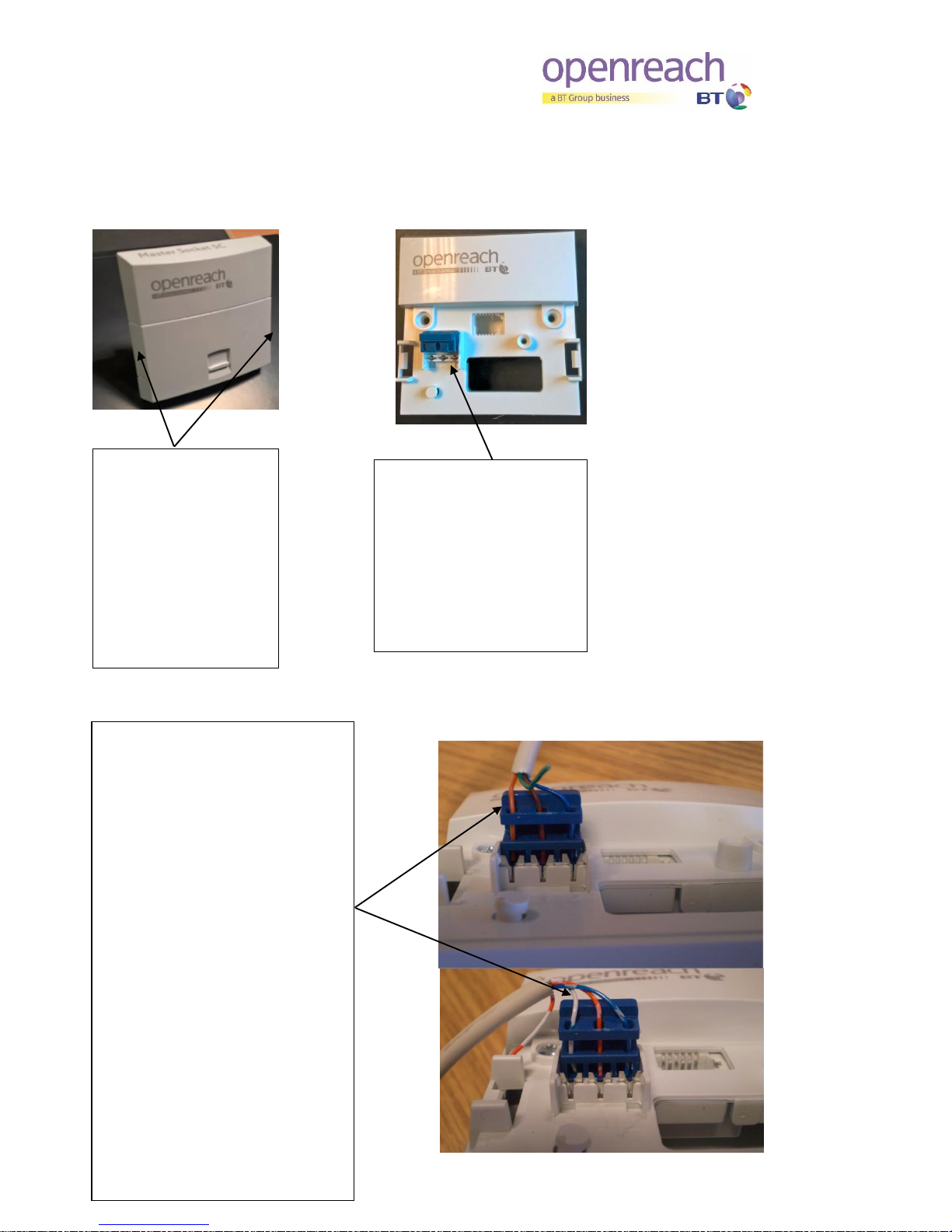
Access to home wiring
connection point and
the network test
socket
Remove the front cover
by pressing the clips on
either side of the front
cover and gently pull the
plate forward.
In home wiring connection
1. Lift up the blue coloured
connection cover.
2. You will see 3 holes used
to separate and connect the
coloured wires for the home
wiring extension cable.
In home wiring connection – You
do not need to remove the
coloured insulation from the wires
3. Thread the BLUE (or BLUE with
WHITE rings) in the right hand hole
above connector number 2. Make
sure the wire passes through the
front and rear holes.
4. Thread the BROWN (or ORANGE
with WHITE rings) in the centre hole
above connector number 3. Make
sure the wire passes through the
front and rear holes.
5. Thread the ORANGE (or WHITE
with BLUE rings) in the left hand
hole above connector number 5.
Make sure the wire passes through
the front and rear holes.
Older version of wiring colours are shown in
brackets above
5 3 2
5 3 2
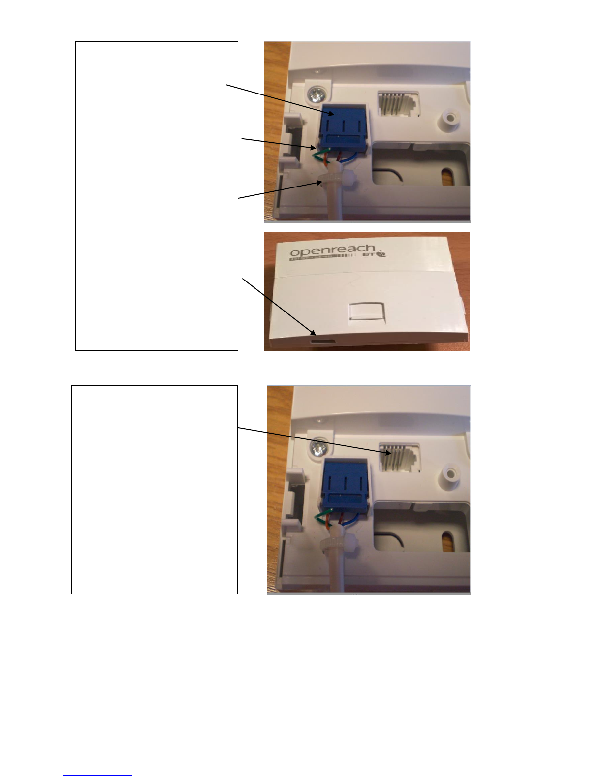
Test Socket used for Fault finding
1. With the front cover removed the
Test socket can be seen at the
“centre top” of the back plate.
2. The Communications Provider CP
may ask their Customer to plug into
the test socket to carry out fault
diagnostic and testing.
3. With the front plate removed the
home wiring will be automatically
disconnected from the network side
and not impact on any fault
diagnostics and testing.
In home wiring connection
6. Push down the blue coloured
connection cover and the home
wiring will now be connected to the
back plate.
7. If there is a spare GREEN (WHITE
with ORANGE rings) coloured wire
it can be trimmed back as it is not
required.
8. Secure the cable to the “post”
below hole 3 using a cable tie
provided – loop the tie round the
cable and post. Ensure the buckle
of the tie is on top and do it up.
Trim off any excess tie. Line up the
cable with the position of the cable
access point on front cover.
9. Push the front cover in place to
make the final connection to the
network

BT, Openreach, and the BT logo and the Openreach identity are
trademarks of British Telecommunications plc.
British Telecommunications plc
Registered Office:
81 Newgate Street, London EC1A 7AJ
Registered in England and Wales no. 1800000
Mk 4 VDSL Filter user instructions
Filter - Data and Phone socket
1. The Mk4 VDSL filter front cover fits
on to the NTE5C back plate and
provides a built in micro filter with
separate telephone and data sockets.
2. It is removed by pressing the clips
on either side of the front cover and
gently pulling the plate forward.
3. Telephone socket.
4. Data socket.
In home wiring and test socket
1. With the Mk4 VDSL filter front
cover removed the test socket can be
seen at the “centre top” of the back
plate and instructions on how it is
used are shown above.
2. The back plate is the same as the
NTE5C. Instructions on how to
connect home telephone wiring to
the blue connection point are shown
above.
In home data wiring
1. The red connection point found
on the reverse of the Mk4 VDSL
filter front cover is used to connect
home data extension wiring.
2. Lift up the red coloured
connection cover and thread the 2
data cable wires in the same way as
shown above for NTE5C and close
the red cover to make the
connection.
 Loading...