

Page 1
www.openplan.com | 844.OPS.OPS1 | [email protected] | REV 09.29.17
XPAND INSTALLATION GUIDE
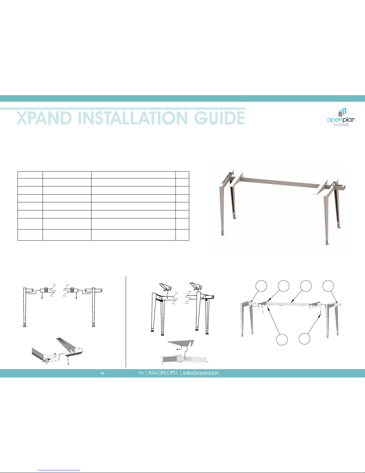
1
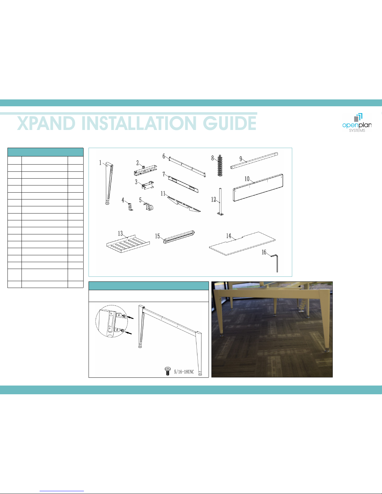
BENCHING ASSEMBLY
PARTS & TOOLS LIST
NO. NAME QTY
1 End Leg 6
2 Mid-Bracket 2
3 Stretcher Bracket 4
4 Cable Tray Clip 24
5 Cable Holder Clip 4
6 Leg Rail Bench 2
7 End Leg Cover 2
8 Wire Management 1
9 Bench Tube 4
10 Screen 2
11 Work Surface Support 4
12 Screen Bracket 4
13 Cable Tray 6
14 Worksurface 4
15 Screen Accessory Rail 2
16 Hex Allen Wrench
(3/16”, 4mm, 2.5mm)
3
17 5/16-18UNC Screws 44
STEP 1
Insert the leg rail bench into the end legs and attach using
provided screws.
Page 2
www.openplan.com | 844.OPS.OPS1 | [email protected] | REV 09.29.17
XPAND INSTALLATION GUIDE
2
BENCHING ASSEMBLY
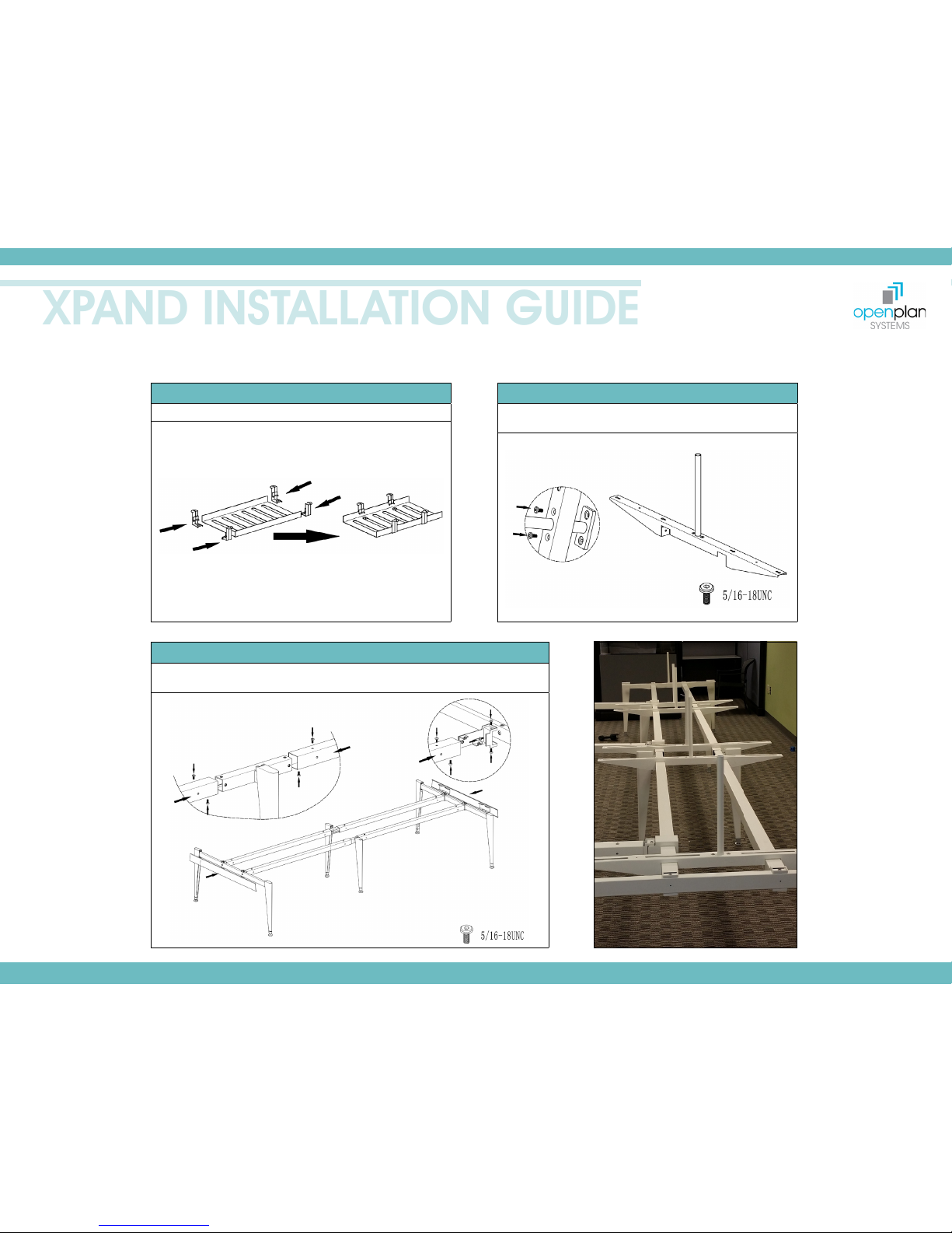
STEP 2
Slide four cable tray clips onto each cable tray.
STEP 3
Insert screen bracket through top bench arms and secure
using provided screws.
STEP 4
Attach end legs assemblies to mid leg assemblies using bench tubes and securing
with provided screws. Attach end leg covers to each end leg assembly.
Page 3
www.openplan.com | 844.OPS.OPS1 | [email protected] | REV 09.29.17
XPAND INSTALLATION GUIDE
3
BENCHING ASSEMBLY
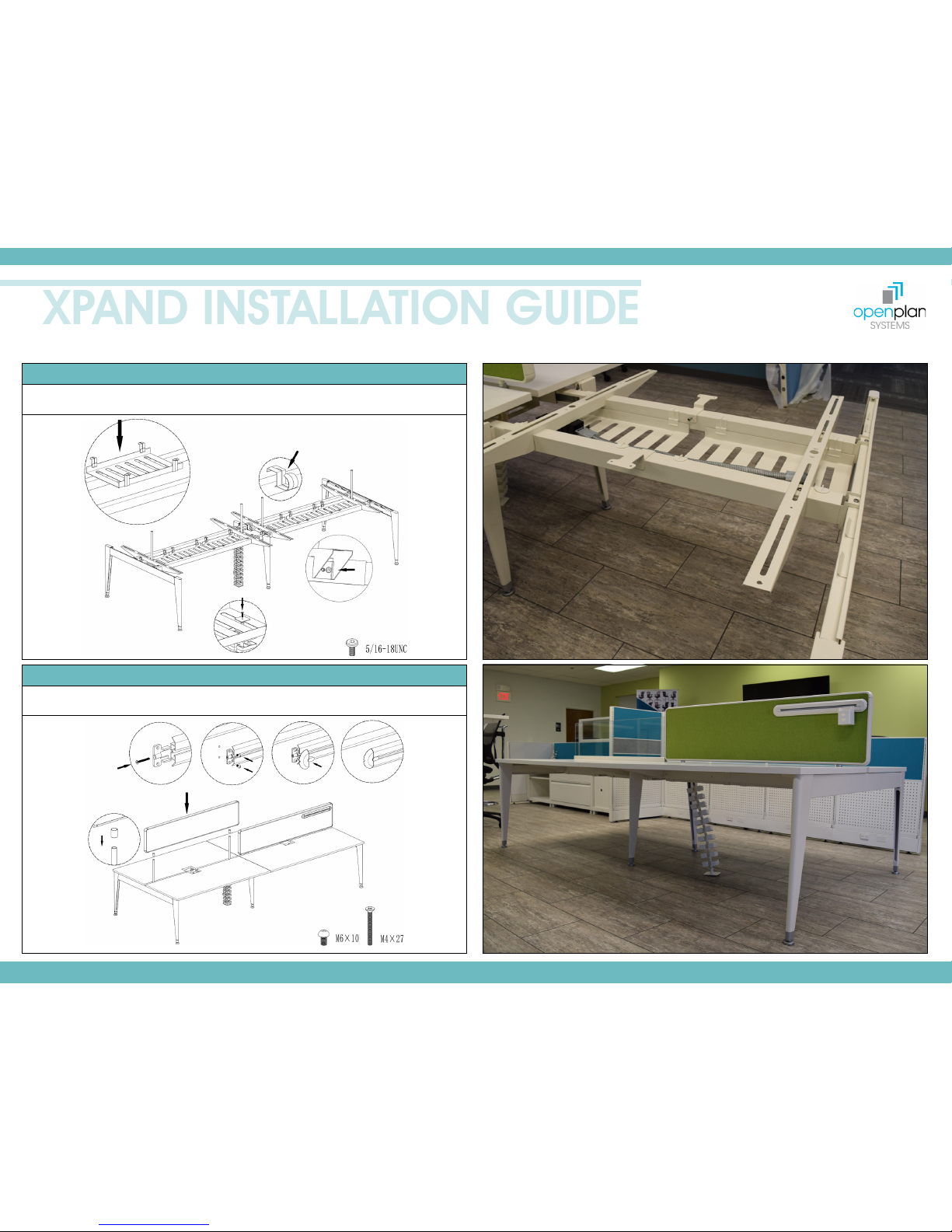
STEP 5
Attach cable trays to stretcher assembly. Secure work surface supports (with screen brackets)
to stretcher assembly using provided screws. Secure wire management with provided screws.
STEP 6
Attach work surfaces to support panels and slide screens onto screen brackets. Attach
screen accessory brackets to screens using provided screws.
Note: Do not use
powered drill to
secure accessory
rail to screens
Page 4
www.openplan.com | 844.OPS.OPS1 | [email protected] | REV 09.29.17
XPAND INSTALLATION GUIDE
4
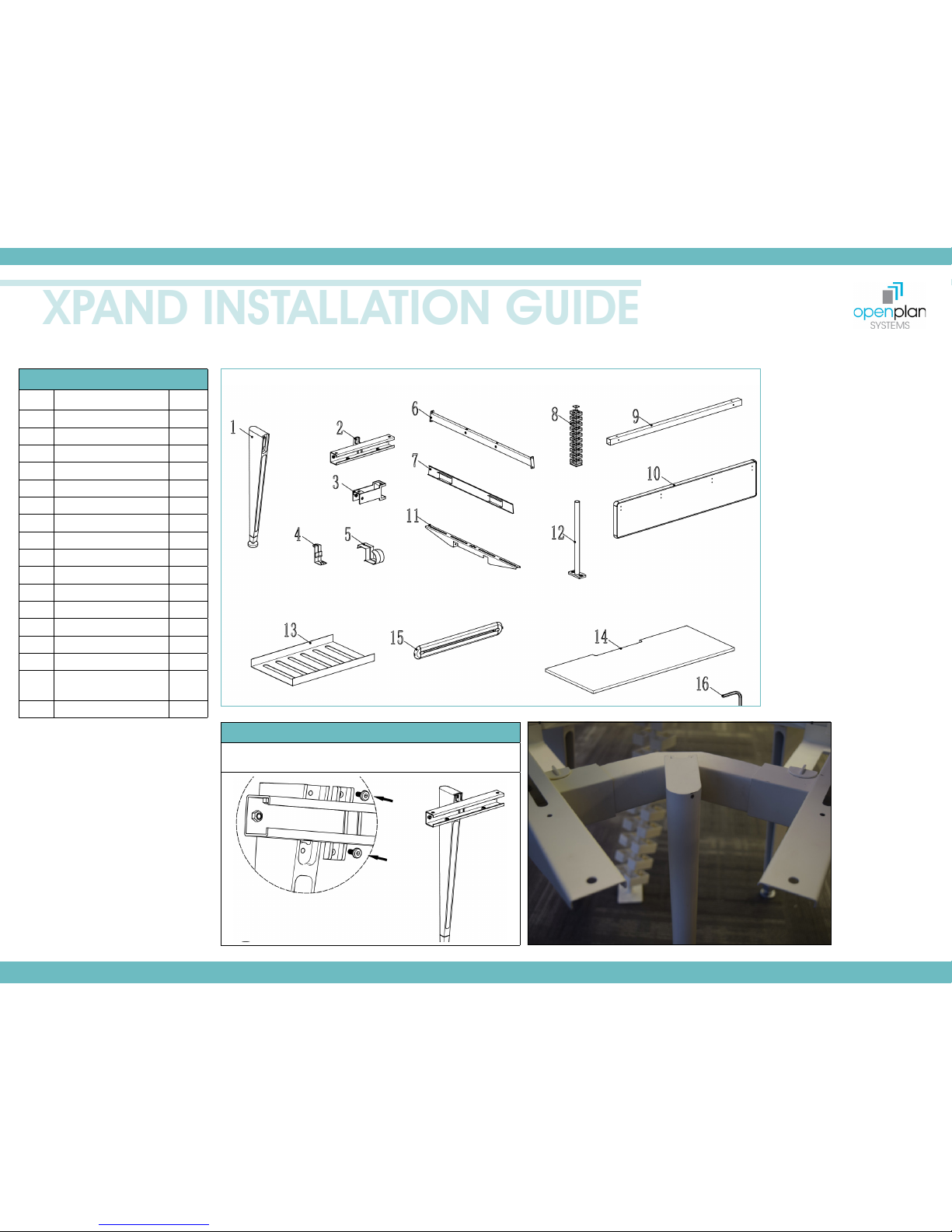
120º BENCHING ASSEMBLY
PARTS & TOOLS LIST
NO. NAME QTY
1 End Leg Assembly 6
2 Mid Leg Inside Bracket 2
3 Stretcher Bracket 4
4 Cable Tray Clip 20
5 Cable Holder Clip 6
6 Leg Rail Bench 2
7 End Leg Cover 2
8 Wire Management 1
9 Bench Tube 4
10 Screen 2
11 Work Surface Support 4
12 Screen Bracket 4
13 Cable Tray 5
14 Worksurface 4
15 Screen Accessory Rail 2
16
Hex Allen Wrench
(3/16”, 4mm, 2.5mm)
3
17 5/16-18UNC Screws 44
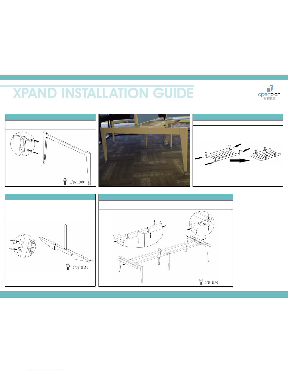
STEP 1
Attach mid-brackets to end legs using provided screws.
Page 5
www.openplan.com | 844.OPS.OPS1 | [email protected] | REV 09.29.17
XPAND INSTALLATION GUIDE
5
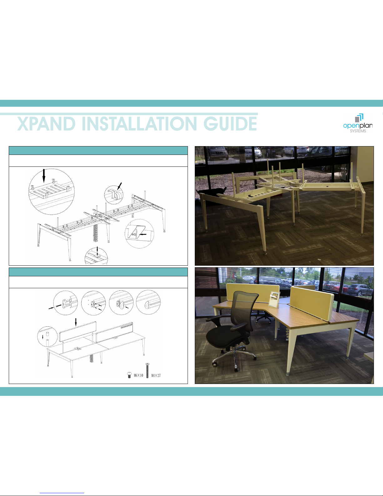
STEP 2
Insert the leg rail bench into the end legs and attach using
provided screws.
STEP 3
Slide four cable tray clips onto each cable tray.
STEP 4
Insert screen bracket through top bench arms and secure
using provided screws.
STEP 5
Attach end legs assemblies to mid leg assemblies using bench tubes and securing with
provided screws. Attach end leg covers to each end leg assembly.
120º BENCHING ASSEMBLY
Page 6
www.openplan.com | 844.OPS.OPS1 | [email protected] | REV 09.29.17
XPAND INSTALLATION GUIDE
6
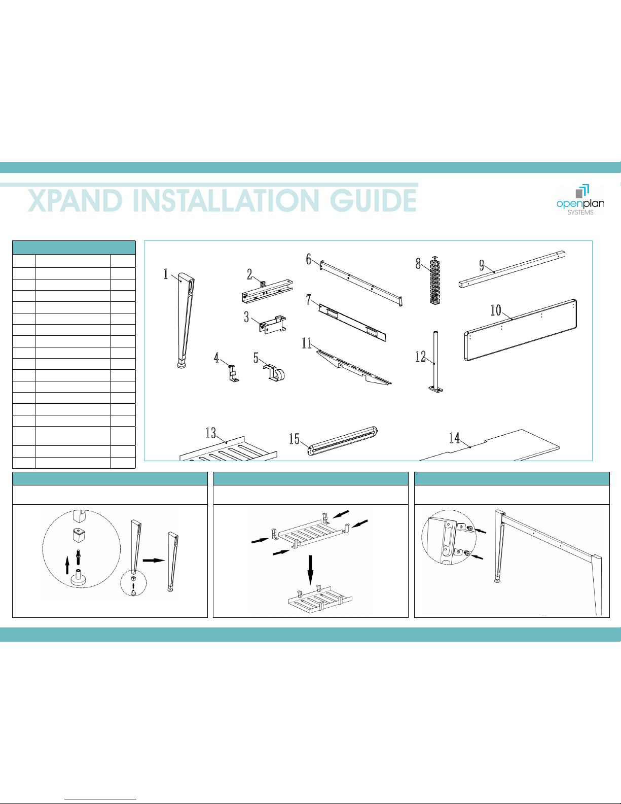
STEP 6
Attach cable trays to stretcher assembly. Secure work surface supports (with screen brackets)
to stretcher assembly using provided screws. Secure wire management with provided screws.
STEP 7
Attach work surfaces to support panels and slide screens onto screen brackets.
Attach screen accessory brackets to screens using provided screws.
120º BENCHING ASSEMBLY
Note: Do not use
powered drill to
secure accessory
rail to screens
Page 7
www.openplan.com | 844.OPS.OPS1 | [email protected] | REV 09.29.17
XPAND INSTALLATION GUIDE
7
ADJUSTABLE HEIGHT ASSEMBLY
PARTS & TOOLS LIST
NO. NAME QTY
1 Height Adjustable Leg 8
2 Inner Screen Insert 4
3 Bench Top Frame 4
4 Bench Tube (Long) 4
5 Screen Accessor y Rail 4
6 Bench Tube (Short) 2
7 Stretcher Bar Bracket 8
8 Stretcher Link Bracket 4
9 Cable Tray Clip 20
10 Cable Tray 5
11 Leg Rail Cover 2
12 Leg Rail 4
13 Work Surface 4
14 Screen 2
15 Hex Allen Wrench
(3/16”, 4mm, 2.5mm)
3
16 M6 Screws 64
17 5/16-18UNC Screws 76
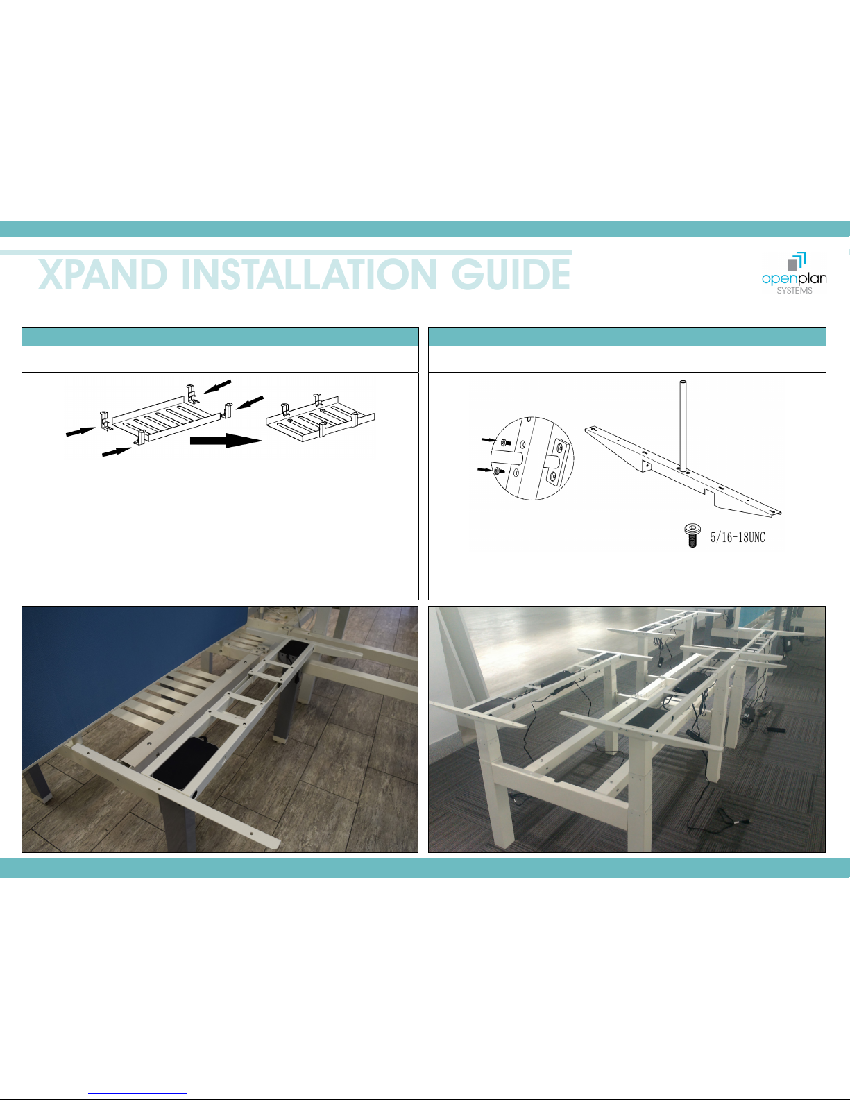
STEP 1
Screw the leg feet onto the bottom of each leg using
provided screws.
STEP 2
Slide four cable tray clips onto each cable tray.
STEP 3
Secure bench tubes (long) to stretcher bar brackets and
attach to leg rails using provided screws.
Page 8
www.openplan.com | 844.OPS.OPS1 | [email protected] | REV 09.29.17
XPAND INSTALLATION GUIDE
8
ADJUSTABLE HEIGHT ASSEMBLY
STEP 4
Attach bench tubes/leg rails to end legs using provided screws. Lower stretcher bars onto end
legs and attach using provided screws.
STEP 5
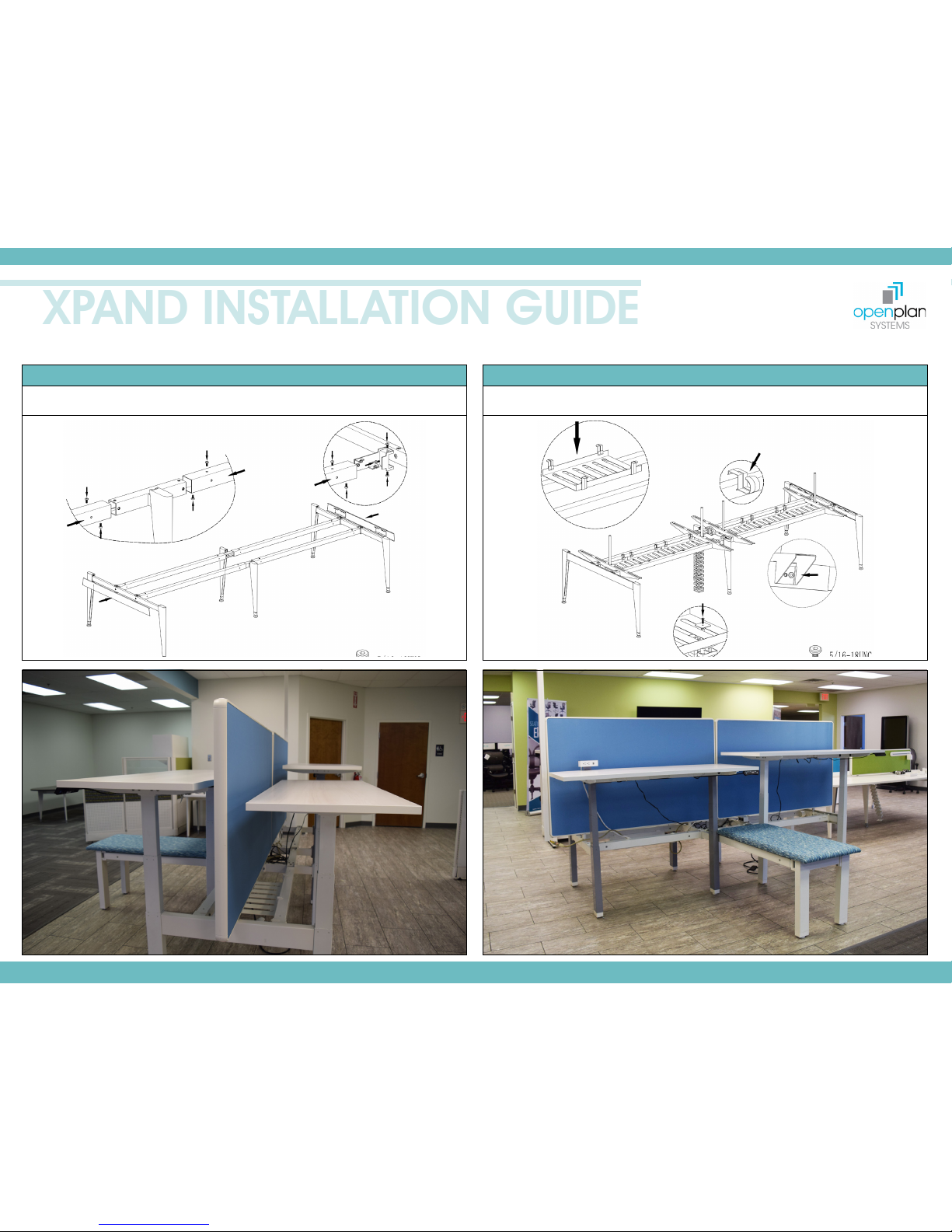
Connect stations together using bench tubes (short) and stretcher link brackets using
provided screws. Secure inner screen inserts to leg rails using provided screws.
Page 9
www.openplan.com | 844.OPS.OPS1 | [email protected] | REV 09.29.17
XPAND INSTALLATION GUIDE
9
ADJUSTABLE HEIGHT ASSEMBLY
STEP 6
Attach cable trays to stretcher assembly. Secure leg rail covers to each end leg assembly.
Secure wire management to cable trays with provided screws.
STEP 7
Attach work surfaces to stretcher bars. Lower screens onto screen brackets. Attach screen
accessory rails to each screen.
Page 10
www.openplan.com | 844.OPS.OPS1 | [email protected] | REV 09.29.17
XPAND INSTALLATION GUIDE
10
CABLE TRAY DUPLEX
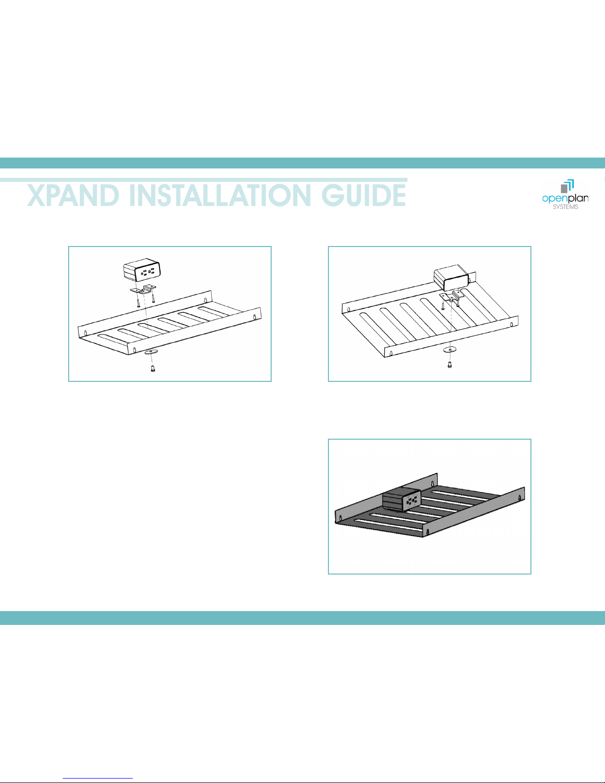
Attach Cable Tray Bracket to Duplex using two wood screws (provided).
Place Duplex and Cable Tray Bracket assembly in desired location of Cable
Management Tray.
Using XP Screw tighten Cable Tray Bracket Plate to the Cable Tray Bracket,
clamping the cable tray tightly.
Page 11
www.openplan.com | 844.OPS.OPS1 | [email protected] | REV 09.29.17
XPAND INSTALLATION GUIDE
11
CABLE TRAY POWER
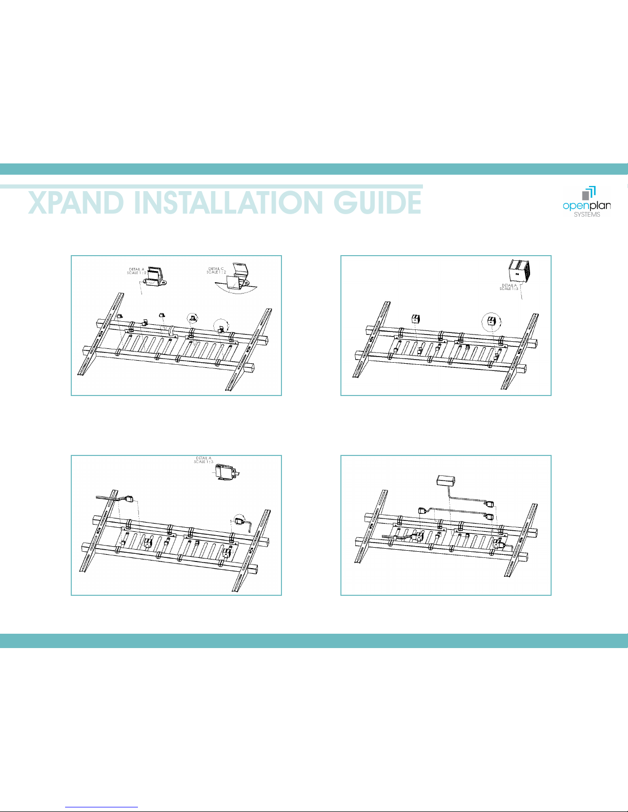
Place cable cord clip (XP-PC) into slotted section of cable tray
(XP-CTA) and twist 90 degrees to secure.
Place Power block clip (XP-PBC) into slotted section of cable tray and
twist 90 degrees to secure.
Place power block (XP-PB) into power block clip (XP-PBC) and snap
into place.
Secure power plugs (XP-PWR) (XP-PE) by placing firmly into power
block. And secure flexible conduit into larger side of cable cord clip
(XP-PC).
Insert remaining Power plugs into power blocks to complete power
connections. Route electrical cables and secure using cable cord
clips (XP-PC).
Page 12
www.openplan.com | 844.OPS.OPS1 | [email protected] | REV 09.29.17
XPAND INSTALLATION GUIDE
12
CABLE TRAY POWER
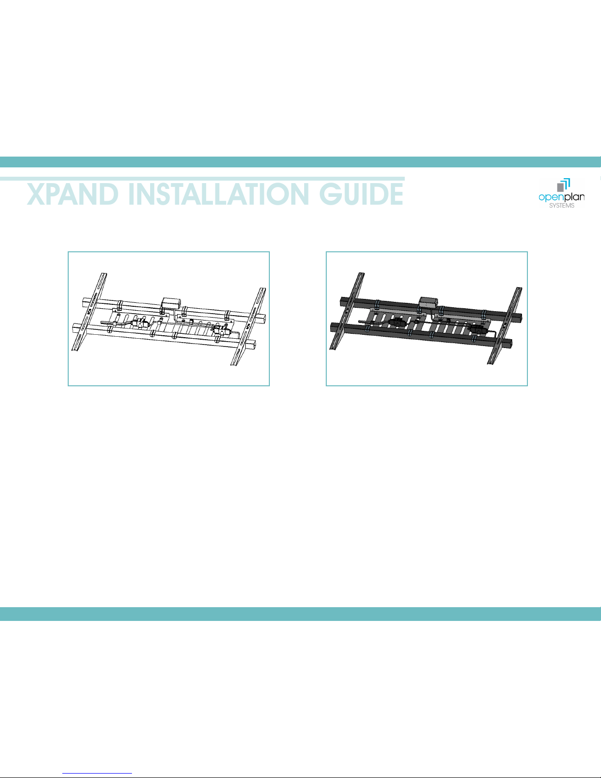
Completed electrical shown secured in place.
Page 13
www.openplan.com | 844.OPS.OPS1 | [email protected] | REV 09.29.17
XPAND INSTALLATION GUIDE
13
ELECTRICAL
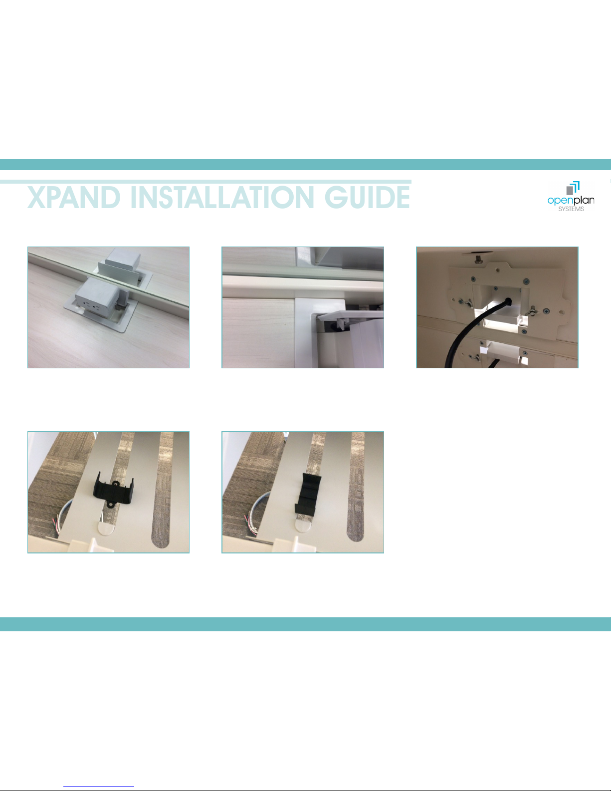
Duplex and grommet cover shown in place.
Grommet will not have door. Grommet does not need
to be fastened to bottom plate it can “float” in place.
Grommet will be flush to back of surface and leading
edge of glass extrusion.
Bottom plate of duplex/grommet shown in place.
NOTE: The three holes without screws in this picture
must be used to securely attach the bottom plate
to the work surface. It is not necessary to attach the
bottom plate to the plastic grommet.
The bracket for the duplex inserts through the slots
provided in the bottom plate and secured with “wing
nuts” provided.
Power block clip shown in place before being twisted
90 degrees to lock in place. Power block mounts
directly to cable management tray.
Power block clip shown in place after twisting 90
degrees.
Page 14
www.openplan.com | 844.OPS.OPS1 | [email protected] | REV 09.29.17
XPAND INSTALLATION GUIDE
14
CABLE TRAY CAT6 BRACKET
SKU: XP-CAT6 | List Price: $24.00
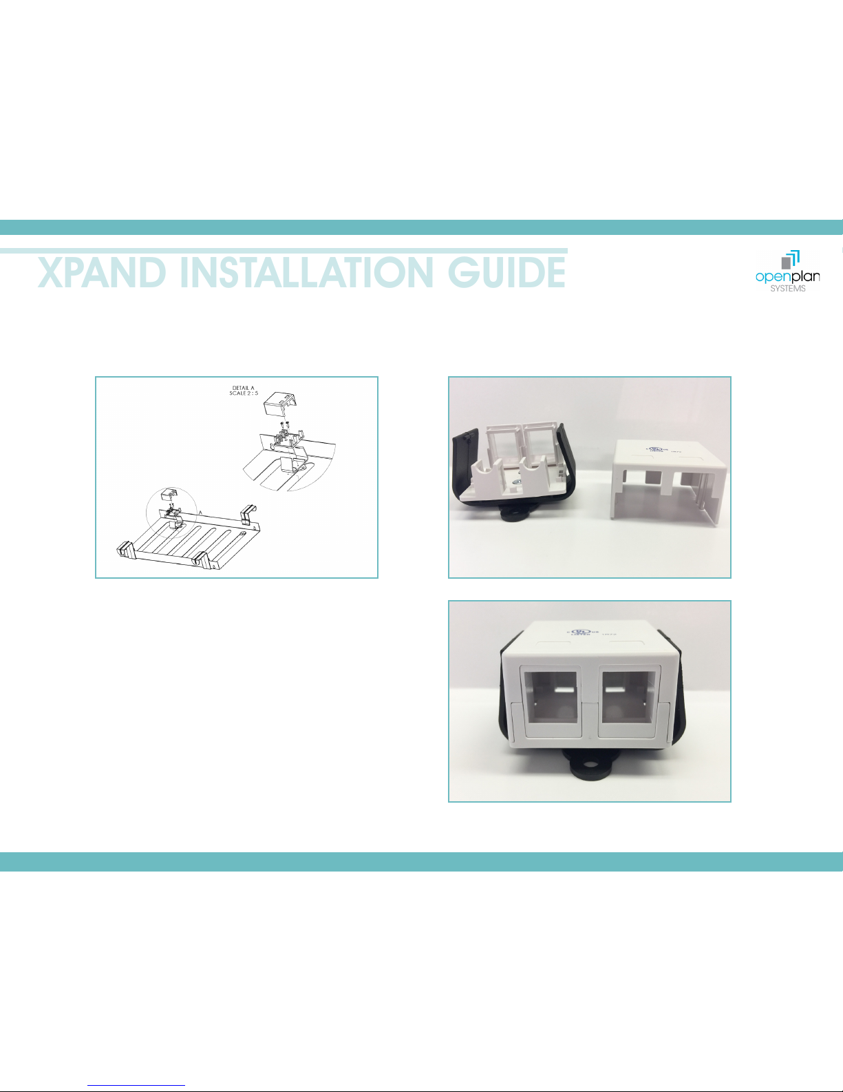
The CAT 6 base will come assembled to the black plastic
bracket.
Place the CAT 6 base and bracket assembly in desired
location on the Cable Tray. Twist the bracket assembly to
secure in place.
Insert/place data components within CAT 6 base. Once
all data components are in place, guide CAT 6 top in
place and “click” to secure.
Page 15
www.openplan.com | 844.OPS.OPS1 | [email protected] | REV 09.29.17
XPAND INSTALLATION GUIDE
15
GLASS SCREEN FRAME
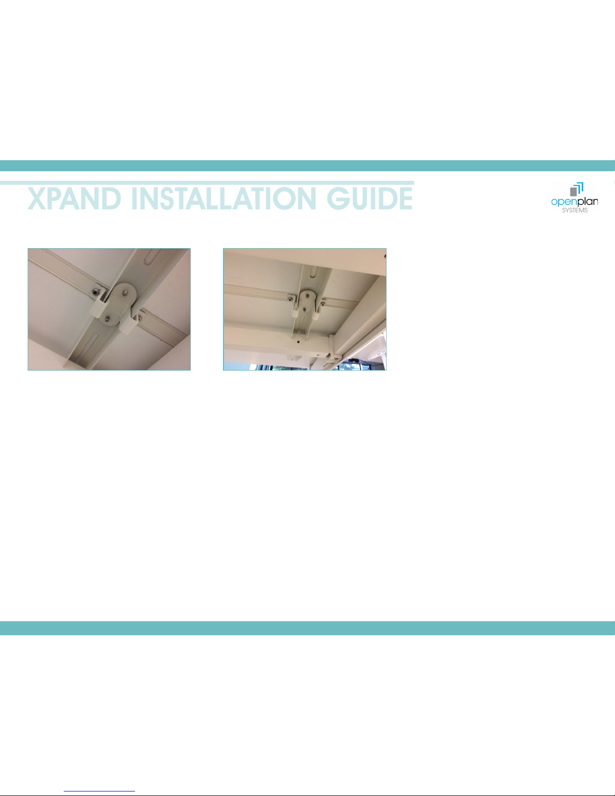
Glass screen bracket shown in place mounted
through work surface support.
Glass screen bracket shown in place.
Page 16
www.openplan.com | 844.OPS.OPS1 | [email protected] | REV 09.29.17
XPAND INSTALLATION GUIDE
16
FRAMELESS GLASS SCREEN
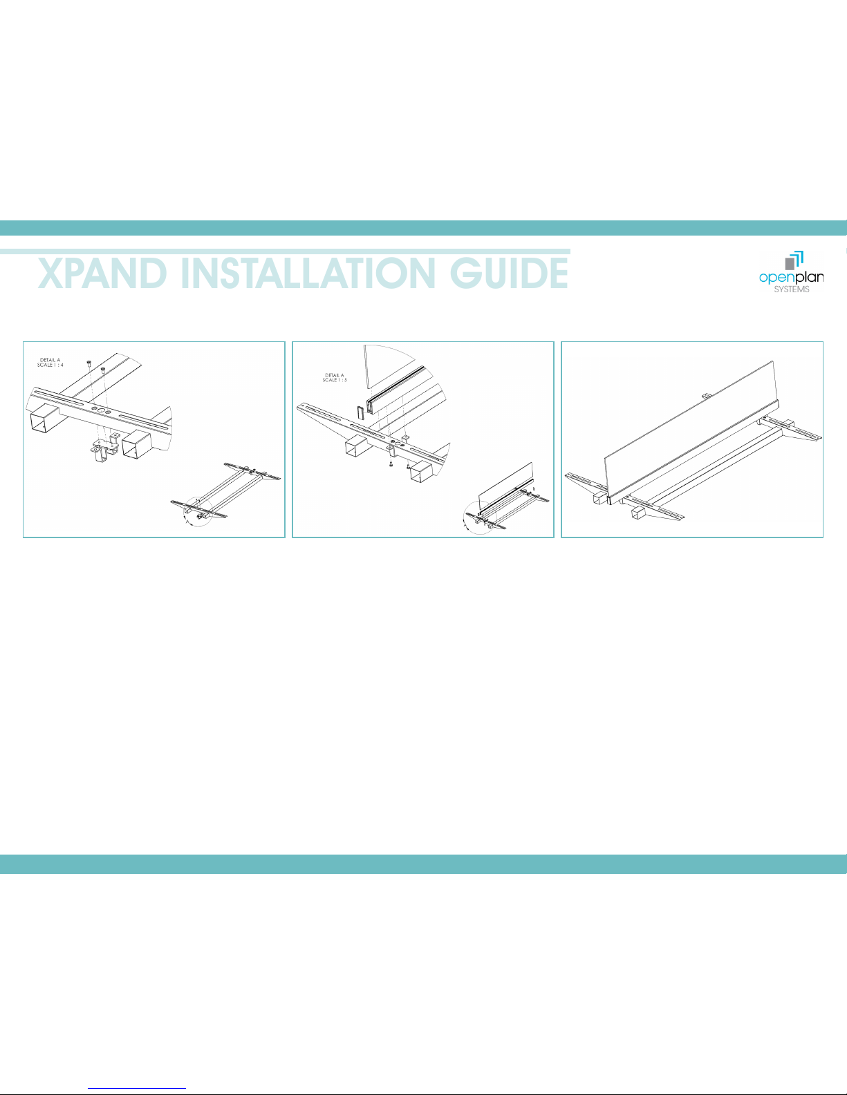
Install glass channel bracket (XP-G-SB) to Work surface support
(XP-WSSA) using two XP-Screws and tighten, as shown.
Install Glass Channel Extrusion (XP-G-E) by fastening to Glass
Channel Brackets (XP-G-SB) using four screws provided.
Carefully insert glass screen into the channel of the glass
extrusion (XP-G-E) ensuring it is fully seated. Seat Glass Channel
Extrusion Endcaps (XP-G-EC) into ends of the Glass Channel
Extrusion (XP-G-E).
Page 17
www.openplan.com | 844.OPS.OPS1 | sales@openplan.com | REV 09.29.17
XPAND INSTALLATION GUIDE
17
XPAND REACH
XP-ELAXX - MLA24
XPAND SINGLE RUN
ITEM NO.
PART NUMBER
DESCRIPTION
QTY
1
XP-ELAXX
XPAND END LEG ASSEMBLY - XX
1
2
XP-MLA24
XPAND MID LEG ASSEMBLY - SINGLE
1
3
XP-SB-SINGLE-XX
STRETCHER BAR SET - SINGLE
1
3.1
XP-SB-XX
Bench Beam/Stretcher - XX
1
3.2
XP-WSSA-24-30
Table Top Support Arm - Single
2
3.3
XP-SCREWS
Hardware Screws
Skt Hd Cap Screw 5/16-18UNC x 5/16" Lg
4
3.4
XP-SCREWS-WS
Work Surface Screw
Ph Pan HD #10-9 x 1" Lg
8
XP-ELAXX-MLA24
XPAND SINGLE RUN
XPAND REACH
NOTES:
1. XP-ELAXX & MLA24 IS IN YOUR INITIAL ASSEMBLY INSTRUCTIONS.
2. CONTINUE YOUR RUN WITH XP-SINGLE-XX & XP-MLA24 UNTIL THE
END. USE AN XP-ELAXX AT THE END.
1 3.1 2
3.4
3.3
3.2
STEP 1
STEP 2
XPAND REACH
XP-ELAXX - MLA24
XPAND SINGLE RUN
NOTES:
XP-ELAXX & MLA24 IS IN YOUR INITIAL ASSEMBLY INSTRUCTIONS.
1.
CONTINUE YOUR RUN WITH XP-SINGLE-XX & XP-MLA24 UNTIL THE
2.
END. USE AN XP-ELAXX AT THE END.
ITEM NO.
PART NUMBER
DESCRIPTION
QTY
1
XP-ELAXX
XPAND END LEG ASSEMBLY - XX
1
2
XP-MLA24
XPAND MID LEG ASSEMBLY - SINGLE
1
3
XP-SB-SINGLE-XX
STRETCHER BAR SET - SINGLE
1
3.1
XP-SB-XX
Bench Beam/Stretcher - XX
1
3.2
XP-WSSA-24-30
Table Top Support Arm - Single
2
3.3
XP-SCREWS
Hardware Screws
Skt Hd Cap Screw 5/16-18UNC x 5/16" Lg
4
3.4
XP-SCREWS-WS
Work Surface Screw
Ph Pan HD #10-9 x 1" Lg
8
1 3.1 2
3.4
3.3
3.2
 Loading...