

Page 1

Lighthouse
User Guide
Revision 2020.Q4.0
2021-1-8
Page 2

2
Lighthouse User Guide
TABLE OF CONTENTS
1. About this User Guide 7
GLOSSARY 7
2. Lighthouse overview 10
2.1 Lighthouse VM host requirements 10
2.2 Lighthouse architecture 10
2.2.1 Lighthouse to Node interactions 11
2.2.2 User to Lighthouse interactions 11
2.2.3 Node organization and filtering 12
2.2.4 Multiple Instance Feature 12
3. Lighthouse VM installation 13
3.1 Lighthouse VM components 13
3.2 VMware vSphere 6.0 via the VMware vSphere 6.0 client on Windows 13
3.2.1 Launch the vSphere Client and connect to a vSphere instance. 14
3.2.2 Import the Lighthouse VM Open Volume Format (.ovf) image 14
3.2.3 Launch the Opengear Lighthouse virtual machine 15
3.2.4 Access the console of a running but headless Opengear Lighthouse instance 16
3.3 VMware Workstation Player on Windows as host 16
3.4 VMware Workstation Pro on Windows as host 17
3.5 VMware Workstation Player or Pro on Fedora Workstation as host 18
3.6 Local deployment on Hyper-V running on Windows 10/Windows Server 2016 18
3.7 Remote Hyper-V deployment with pre-authenticated user 18
3.8 Remote Hyper-V deployment with different user 19
3.9 VirtualBox on Windows as host 19
3.10 VirtualBox on macOS as host 20
3.11 VirtualBox on Ubuntu as host 21
3.12 VirtualBox on Fedora Workstation as host 22
3.13 Virtual Machine Manager (KVM) on Ubuntu as host 23
3.14 Boxes on Fedora Workstation as host 23
3.15 Boxes on CentOS as host 24
3.16 Azure environment 24
3.17 Amazon Web Services (AWS) environment 25
4. First boot of the Lighthouse VM 28
5. Initial system configuration 30
5.1 Lighthouse IP addressing 30
5.2 Loading Lighthouse 30
5.3 Login to Lighthouse 31
Page 3

3
Lighthouse User Guide
5.4 Network connections 33
5.5 Setting the Lighthouse hostname 34
5.6 Adding external IP addresses manually 34
5.7 Setting the Lighthouse internal clock 35
5.8 Examine or modify the Lighthouse SSL certificate 36
5.9 Examine or modify Lighthouse Session Settings 37
5.10 Examine or change the MTU of the Lighthouse VPN tunnel 38
5.11 Enable or modify SNMP Service 38
5.12 Cellular Health Settings 39
5.13 Lighthouse MIBs 39
6. Shut Down or Restart Lighthouse 50
6.1 Shut down a running Lighthouse instance 50
6.2 Restarting a running Lighthouse instance 50
7. Using Lighthouse 50
7.1 Licensing third-party nodes before enrollment 51
7.1.1 Adding a license using the Lighthouse UI 51
7.1.2 Showing installed licenses in the Lighthouse UI 51
7.1.3 Showing installed licenses via the Local Terminal 52
7.2 Enrolling nodes 53
7.2.1 Enrollment overview 53
7.2.2 Enrollment bundles 53
7.2.3 Creating an enrollment bundle 54
7.2.4 Structure of an enrollment bundle 55
7.2.5 Enrollment via Lighthouse Web UI 56
7.2.6 Enrollment via Node Web UI 58
7.2.7 Lighthouse Enrollment via OM, ACM, CM, and IM Web UI 58
7.2.8 Mass Enrollment using ZTP 58
7.2.9 Enrollment via USB drive 59
7.3 The Enrolled Nodes page 60
7.4 Filtering pages displaying nodes 61
7.4.1 Filtering using the Free Text Search field 62
7.4.2 Filtering using the Smart Group Filtering drop-down menu 62
7.4.3 Filtering using the Managed Device Filtering drop-down menu 63
7.5 Creating Smart Groups 64
7.6 Editing an existing Smart Group 65
7.7 Creating Managed Device Filters 66
7.8 Editing an existing Managed Device Filter 66
7.9 Connecting to a node’s web-management interface 67
7.10 Connecting to a node’s serial ports via Console Gateway 68
7.10.1 Access via HTML5 Web Terminal 69
7.10.2 Access via SSH 69
7.10.3 Example Console Gateway session 71
Page 4

4
Lighthouse User Guide
8. Lighthouse user management 72
8.1 Password fields in Lighthouse 72
8.2 Creating new groups and roles 72
8.3 Modifying existing groups 78
8.4 Use an existing group as a template for a new group 79
8.5 Creating new local users 80
8.6 Modifying existing users 81
8.7 Expire user password 82
8.8 Setting password policy 83
8.9 Deleting users 84
8.10 Disabling a Lighthouse root user 84
8.11 Configuring AAA 84
8.11.1 LDAP Configuration 85
8.11.2 RADIUS configuration 86
8.11.3 TACACS+ configuration 87
8.12 Setting login restrictions 88
9. Notifications 90
10. Lighthouse central configuration 93
10.1 Creating new users and groups templates 93
10.2 Modifying existing users and groups templates 95
10.3 Deleting users or groups from a template 96
10.4 Deleting users and groups templates 96
10.5 Creating new authentication templates 96
10.6 Modifying existing authentication templates 97
10.7 Deleting authentication templates 98
10.8 Creating new script templates 98
10.9 Modifying existing script templates 99
10.10 Deleting script templates 100
10.11 Apply Templates 100
10.12 Manually Activate Secure Provisioning or Software Defined Infrastructure via Template 102
11. Multiple Instance 104
11.1 Licensing 104
11.2 Setting up a multiple instance 104
11.3 Multiple instance configuration 106
11.4 Disconnecting a secondary instance 108
11.5 Promoting a secondary instance 108
Page 5

5
Lighthouse User Guide
11.6 Upgrading a multiple instance Lighthouse 109
12. Command line tools 110
12.1 node-info 110
12.2 node-upgrade 111
12.3 ogadduser 112
12.4 ogconfig-cli 113
12.4.1 Commands to try from within the ogconfig-cli tool 113
12.4.2 Config searches using ogconfig-cli 113
12.4.3 Changing a configuration from within ogconfig-cli 113
12.4.4 Configuration validation from within ogconfig-cli 114
12.4.5 Modify LHVPN keepalive timeout for different sized deployments with ogconfig-cli 114
12.4.6 Support for mounting the hard disks with ogconfig-cli 114
12.4.7 Support for multiple instance Lighthouse with ogconfig-cli 115
12.5 oglicdump 115
12.6 cron 116
12.7 sysflash 117
12.8 Selecting nodes using shell-based tools 117
12.8.1 Select all nodes 117
12.8.2 Running commands on selected nodes 117
12.9 Add a custom 2nd NIC to a Lighthouse instance 118
13. Lighthouse CLI and REST API logging 121
13.1 Logging overview and limitations 121
13.2 Using ogconfig-cli to enable logging 121
13.3 Example logs 122
13.4 Checking if logging is enabled 122
13.5 Enable logging 123
13.6 Disable logging 123
14. System upgrades 124
14.1 Upgrading the system from within Lighthouse 125
14.2 Upgrading the Lighthouse system via the Local Terminal 126
15. Adding Extra Disk Space to Lighthouse 127
15.1 Adding a New Disk 127
15.2 Using the new disk to increase the lh_data logical volume 129
16. Troubleshooting 130
16.1 Finding the current Lighthouse instance version 130
16.1.1 Using the web UI 130
16.1.2 Via the local Lighthouse shell 130
16.1.3 Other information sources related to a Lighthouse instance’s version 131
16.2 Technical support reports 131
Page 6

6
Lighthouse User Guide
16.2.1 Generate a support report via the Lighthouse interface 131
16.2.2 Generate a support report via the local terminal 132
16.3 Configuration Backup 133
16.4 Configuration Restore 134
16.5 Returning a Lighthouse instance to factory settings 135
18. Changing Docker IP Ranges 136
18. EULA and GPL 138
Page 7

7
TERM
DEFINITION
AUTHDOWNLOCAL (RADIUS/LDAP/AAA)
When this authentication option is selected, if
remote authentication fails because the user
does not exist on the remote AAA server, the
user is denied access.
AUTHLOCAL (RADIUS/LDAP/AAA)
When this authentication option is selected, if
remote authentication fails because the user
does not exist on the remote AAA
server, Lighthouse tries to authenticate the user
using a local account.
CELLULAR HEALTH
Status of the cellular connection of a node.
DARK MODE
Changes the user interface to display mostly
dark colors, reducing the light emitted by device
screens.
DOCKER
An open platform for developing, shipping, and
running applications. Docker enables you to
separate your applications from your
infrastructure so you can deliver software
quickly.
Docker powers the NetOps platform within the
Lighthouse product.
ENROLLMENT
Connecting a node to Lighthouse
ENROLLMENT BUNDLE
Used to assign a number of tags to a set of
nodes when they are enrolled. During enrollment,
the bundle is specified using its name, and a
bundle-specific enrollment token.
ENROLLED NODE
Node that has been connected to Lighthouse and
is ready for use.
ENROLLMENT TOKEN
A password that authorizes the node with
Lighthouse. Used when performing Node-based,
or ZTP enrollment.
INSTANCE
A single running Lighthouse.
LIGHT MODE
Changes the user interface to display mostly
light colors. This is the default UI setting.
LIGHTHOUSE
System for accessing, managing and monitoring
Opengear console servers.
Lighthouse User Guide
1. About this User Guide
This manual covers Lighthouse and is current as of 2020.Q4.0. When using a minor release, there may or may not be a
specific version of the user guide for that release. The current Lighthouse user guide can always be found here.
NOTE: OPERATIONS MANAGER support is partial for this release. Mass node enrollment using ZTP, enrollment via USB
drive, and SNMP information are not currently supported for OPERATIONS MANAGER nodes. All template types are
supported.
GLOSSARY
Terms used in this guide to define Lighthouse elements and concepts are listed below.
Page 8

8
LIGHTHOUSE ENTERPRISE
Offers an elevated centralized management
solution with additional functionality. It supports
growing trends such as edge computing and SDWAN with High Availability and Remote IP
Access.
LIGHTHOUSE VPN
The OpenVPN based connections that the
Lighthouse instance has with the nodes it is
managing
LOCALAUTH (RADIUS/LDAP/AAA)
When this authentication option is selected, if
local authentication fails, Lighthouse tries to
authenticate the user using a remote AAA server.
MANAGED DEVICE
A device that is managed via a node through a
serial, USB, or network connection.
MULTIPLE INSTANCE
Access nodes through multiple Lighthouse
instances at the same time.
NODE
A device that can be enrolled with Lighthouse,
allowing it to be accessed, managed, and
monitored. Currently, Opengear console servers
are supported on a standard license, with
support for other vendors Console Servers
available as an add-on.
PASSWORD POLICY
Administrative users can define rules for
Lighthouse user passwords including length,
types of characters, reuse, and expiration period.
PENDING NODE
A node that has been connected to Lighthouse
and has been configured with a VPN Tunnel, but
which has not yet been approved for access,
monitoring, or management. The approval
operation can be automated by configuring
Lighthouse to auto- approve nodes.
PRIMARY INSTANCE
The main instance of Lighthouse used for
updating configuration and node enrollment.
REMOTE LOGGING/REMOTE SYSLOG
The ability to send logs to a remote server, for the
offsite storage and review of logs.
REPLICATION
Automatic copying of the primary Lighthouse
database to any connected dependent
instances. Replication ensures that these
instances mirror the same information and
maintains connections to the same nodes.
ROLE
A set of access rights for a particular group.
Three roles are defined within Lighthouse:
Lighthouse Administrator, Node Administrator,
and Node User.
SECONDARY/DEPENDENT INSTANCES
Redundant instances of Lighthouse that are
used to access Lighthouse information and
connected nodes.
SMART GROUP
Dynamic filter used to search for particular
nodes, or for defining the access rights of a
Lighthouse User Guide
Page 9

9
group of users. Smart Groups use node
properties, as well as tags defined by users.
TAG
User-defined attribute and value that is assigned
to one or more nodes. Tags are used when
creating Smart Groups for filtering views or
access to nodes.
Lighthouse User Guide
Page 10

10
Lighthouse User Guide
2. Lighthouse overview
2.1 Lighthouse VM host requirements
To host Lighthouse, the VM needs to be configured to support a 20GB SCSI disk. As of Lighthouse 20.Q4.0,
a second NetOps disk is no longer required, and is included as a part of the normal Lighthouse disk.
Modules will need to be synchronized with the latest version from Dockerhub, or updated using the offline
installer
•
Lighthouse deploys as an application running in a Linux-based virtual machine (VM). The
Lighthouse binary is available in open (for VM managers such as Boxes, KVM, and VirtualBox),
VMware and Hyper-V specific Virtual Machine formats, image format. Lighthouse can also be run
through cloud hosting services including Amazon’s AWS, and Microsoft Azure.
•
To run a Lighthouse VM, the host computer must be able to run a VM manager and at least one full
64-bit Linux-based virtual machine.
•
To host Lighthouse, the VM needs to be configured to support:
o 20GB SCSI disk. (This can be expanded or reduced after installation and first run)
o 1 x network interface card, preferably paravirtualised (virtio, vmxnet3), Realtek rtl8139, or
Intel e1000 are also supported, bridged.
o VGA console for initial setup.
To dimension CPU and RAM resources, follow these guidelines:
CPU and RAM utilization increase with the number of enrolled nodes.
For small deployments (Up to 500 nodes), allocate:
• 2 x 64-bit CPU cores.
• 8GB RAM.
For medium deployments (between 500 and 1000 nodes), allocate:
•
4 x 64-bit CPU cores.
•
18GB RAM.
For large deployments (more than 1000), allocate:
•
4 x 64-bit CPU cores.
•
32GB RAM.
For large deployments, please contact us for guidance on the deployment options, including low and zerotouch enrollment. The performance and limitations are dependent on network deployment.
Additionally, Lighthouse VPN keepalive timeout needs to be modified according to the size of deployment.
2.2 Lighthouse architecture
Lighthouse provides a platform for centrally accessing, managing, and monitoring Opengear console
servers.
Console servers connect to a central Lighthouse instance over an OpenVPN tunnel, and are accessed,
managed, and monitored via services transported over the VPN tunnel. In Lighthouse terminology, the
console server is referred to as the node.
Page 11

11
Lighthouse User Guide
NOTE: This diagram depicts High Availability. Without a secondary Lighthouse set up, the
diagram remains the same but without the secondary elements.
2.2.1 Lighthouse to Node interactions
For management and monitoring operations, Lighthouse queries and pushes data to and from a REST API
on the node.
When a node is enrolled in Lighthouse, Lighthouse generates an X.509 certificate. This certificate
authenticates the OpenVPN tunnel and provides the node access to the Lighthouse REST API. The node
also imports a Certificate Authority from Lighthouse and uses that to allow Lighthouse access to the node’s
REST API. Lighthouse also provides a public SSH key to the node, which allows Lighthouse to access the
node’s serial ports via SSH.
For serial access, a node’s serial port subsystem is connected to via SSH. Users can also access the node's
Web UI, which is reverse-proxied through the VPN tunnel.
2.2.2 User to Lighthouse interactions
Users interact with Lighthouse via an Ember.js JavaScript application, which communicates with
Lighthouse via a REST API. This REST API can integrate Lighthouse into other systems. Documentation for
this API is available for direct customer use.
While Lighthouse supports REST API versions v1, v1.1, v2, v3, v3.1 and v3.2, some of the endpoints in v1,
v1.1, and v2 have been deprecated, meaning the functionality and expected request body may be different.
We advise using the v3.2 to ensure the latest available functionality.
Page 12

12
Lighthouse User Guide
2.2.3 Node organization and filtering
To help search, organize, and filter access to nodes, Lighthouse uses Smart Groups which allow node
properties and user-supplied tags, consisting of a name and value, to be compiled into a search expression.
These search expressions can be saved and used to filter the various lists of nodes in the Web UI, for
example when selecting a serial port to connect to or to connect to the node’s Web UI. They can also be
used for selecting the nodes that a particular group of users can access.
To help locate managed devices, Lighthouse includes Managed Device Filtering which allows users to
search for port labels on a node. This search can be saved and applied on the MANAGE > MANAGED
DEVICES > Console Gateway page.
2.2.4 Multiple Instance Feature
Starting with version 5.3, Lighthouse offers a Multiple Instance feature that allows you to set up a
secondary or dependent instance of Lighthouse that automatically receives updates from a primary
Lighthouse instance and maintains connections to all of its remote nodes.
Secondary instances are read-only. They may be used to view Lighthouse information specific to that
instance, and to connect to its nodes via pmshell. Configuration changes must be performed on the
primary instance, which will then update the information displayed on the secondary instance.
The multiple instance feature has the following limitations:
• Up to ten secondary instances can be enrolled.
• Multiple instance support is available starting with Lighthouse 5.3.
• Secondary Lighthouse instances are read-only. We recommended that you preconfigure instance
specific settings such as hostname, external endpoints, and time zone on a secondary instance
before adding it to the primary in a normal way through UI.
• Dependent Lighthouse instances must have zero nodes enrolled before being enrolled to the
primary Lighthouse.
• Removing a dependent Lighthouse instance will initiate a factory reset.
• If external endpoints on the primary or secondary Lighthouses are updated after a secondary
Lighthouse has been enrolled, it may break replication.
• Only Opengear nodes with a version that supports multiple instance will connect to the secondary
instance, which means CS 4.4.1, or later and NGCS 19.Q2.0 or later. Nodes that don't support
multiple instance will behave normally on the primary.
• The secondary instance UI offers a limited display.
See Chapter 10 for specific information on using the multiple instance feature.
Page 13

13
Lighthouse User Guide
3. Lighthouse VM installation
To host Lighthouse, the VM needs to be configured to support a 20GB SCSI disk.
3.1 Lighthouse VM components
Lighthouse VM is available in several formats:
•
An Open Volume Format file — lighthouse-20.Q4.0-ovf.zip — inside a PKZip archive. This
is for use with virtual machine managers such as KVM and Virtual Box.
•
A VMware configuration file — lighthouse-20.Q4.0-vmx.zip —inside a PKZip archive. This is
for use with virtual machine managers from VMware.
•
A raw (.hdd) file, lighthouse-20.Q4.0-raw.hdd.tar. This file has been compressed with tar
and is for use with hosting services such as ElasticHosts.
•
An Open Virtual Appliance file — lighthouse-20.Q4.0.ova. This is for use with virtual
machine managers such as VM and Virtual Box as well as for use with virtual machine managers
from VMware.
•
A Hyper-V configuration file with Powershell script — lighthouse-20.Q4.0-hyperv.zip —
inside a PKZip archive. This is for use in Microsoft Hyper-V deployment.
•
A Microsoft Azure file, lighthouse-azure.zip for deploying on Azure.
•
An Amazon Web Services bootstrap shell scripts aws_bootstrap.sh and lighthouse-aws-
bootstrap.sh, and the lighthouse-20.Q4.0.aws.raw.tar image for deploying on AWS.
•
An upgrade file, lh_upg.
NOTE: Due to disk restructuring, there are no lh_upg files for 20Q3.0.
•
The optional lighthouse-nom.vhd file for NetOps.
NOTE: The NetOps disk is only required to run NetOps modules (including Secure Provisioning,
and IP Access) or to run a Docker container on Lighthouse. To install:
1. Upload the lighthouse-nom.vhd file for netops.
2. Go to images.
3. Create a new image.
4. Choose the boot disk by navigating to the storage explorer and selecting the
lighthouse.vhd disk image. Optionally add the netops disk under managed disks.
3.2 VMware vSphere 6.0 via the VMware vSphere 6.0 client on Windows
This procedure assumes VMware vSphere 6.0 is installed and running on available hardware. User must
have access to a Windows computer on which the VMware vSphere 6.0 client is installed and that this
installed client application can connect to and manage the VMware Sphere 6.0 instance. Finally, a copy of
the Lighthouse binary in Open Volume Format is required, the .ovf file, either copied to the Windows
computer running the VMware vSphere 6.0 client or available via a URL.
This procedure was tested using the VMware Sphere Client 6.0 running on Windows 7 Enterprise SP 1.
Page 14
14
Lighthouse User Guide
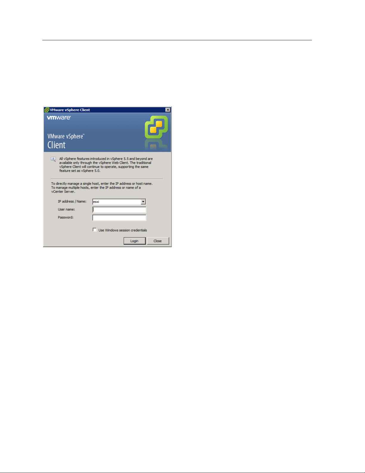
3.2.1 Launch the vSphere Client and connect to a vSphere instance.
1. Launch the VMware vSphere Client. The simplest way is to use the Start Menu shortcut added during
installation.
Start > All Programs > VMware > VMware vSphere Client
The VMware vSphere Client opens a login window.
2. Select the IP address or name of the VMware vSphere instance where Lighthouse will be installed from
the IP address/Name drop-down list.
3. Enter the User name and Password required to gain management privileges to the selected VMware
vSphere instance.
4. Click Login or press Return.
The login window displays progress text in the bottom left corner:
Connecting
Loading inventory
Loading main form
Displaying main form
The vSphere main form window opens.
3.2.2 Import the Lighthouse VM Open Volume Format (.ovf) image
1. From the vSphere Client menu bar, choose File > Deploy OVF Template.
The Deploy OVF Template window appears, with the first stage, Source, pre-selected.
2. If the file Opengear Lighthouse VM.ovf is on a remote computer via a URL, enter this URL in the
Deploy from a file or URL field. Otherwise, click Browse. An Open dialog appears.
Navigate to the directory containing the file Opengear Lighthouse VM.ovf.
Select Opengear Lighthouse VM.ovf and click Open.
Page 15
15
Lighthouse User Guide
3. The Deploy OVF Template window opens again, with the Opengear Lighthouse VM.ovf file
listed in the Deploy from a file or URL combo-box. Click Next.
4. The OVF Template Details stage appears, showing basic information about the Lighthouse VM
encapsulated by the .ovf file. Click Next.
5. The Name and Location screen appears with the Name field pre-populated and pre-selected.
The default name is Opengear Lighthouse VM. To change this, enter a new name. Click Next.
6. The Disk Format screen displays which data-store the Lighthouse VM’s virtual disk uses, how much
free space the virtual disk has available and which provisioning scheme is being used. Click Next.
7. The Network Mapping screen shows which destination or inventory network the Lighthouse VM’s
virtual network is mapped to. Click Next.
8. The Ready to Complete screen appears, listing the basic properties of the about-to-be-deployed
virtual machine. To be able to power-up the new virtual machine after deployment, select the Power
on after deployment checkbox. Click Finish.
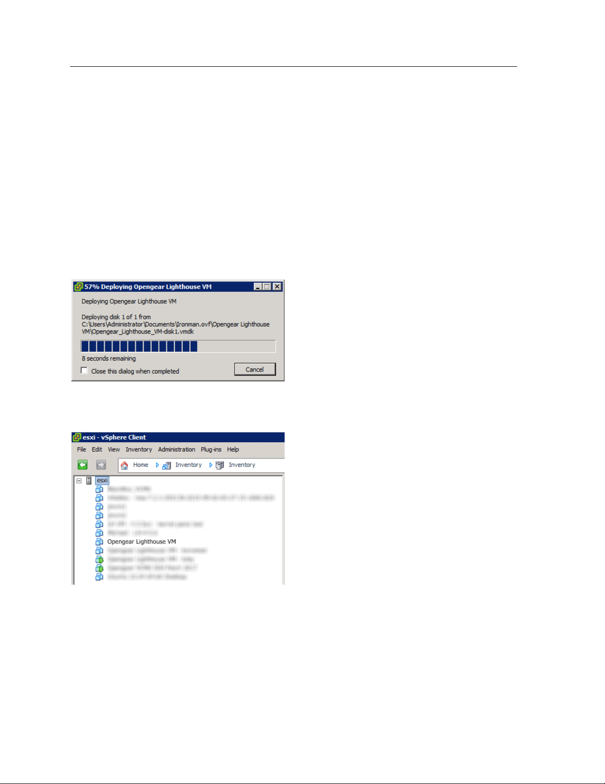
9. The Deploying Opengear Lighthouse VM progress dialog appears.
10. Once deployment has finished the Deployment Completed Successfully alert appears. Click Close.
The new virtual machine is now deployed and appears in the inventory list.
3.2.3 Launch the Opengear Lighthouse virtual machine
The vSphere Client provides several ways of launching a Virtual Machine hosted on a vSphere instance.
Begin by selecting the Opengear Lighthouse VM from the vSphere Client’s inventory list. The selected VM
can then be launched by doing one of the following:
•
Select Inventory > Virtual Machine > Power > Power On.
•
Press Ctrl-B.
Page 16

16
Lighthouse User Guide
•
Click the Power on the virtual machine link in the Basic Tasks section of the Getting Started tab.
This option requires the Getting Started tab be front-most. If it is not already the front-most tab,
make it active by clicking it.
•
Select Inventory > Virtual Machine > Open Console and then:
o Click Power On in the console tool bar, or
o Choose VM > Power > Power On from the console menu bar, or
o Press Ctrl-B.
NOTE: Only the fourth option above results in the running virtual machine being accessible from within
the vSphere Client. The first three boot the Lighthouse VM and get it running headless.
3.2.4 Access the console of a running but headless Opengear Lighthouse instance
If direct interaction with a running but headless *Opengear Lighthouse VM* is required, open a console
window.
Select the running Opengear Lighthouse VM in the vSphere Client’s inventory list, then do one of the
following:
•
Select Inventory > Virtual Machine > Open Console or
•
Right-click and select Open Console from the contextual menu that appears.
NOTE: A Lighthouse VM is running a bash shell with no other interactive options. As a result, when the
vSphere Client opens its console window, the Lighthouse VM captures the mouse pointer, making it
unavailable for use by any other window. Press CTRL+ALT to release the pointer.
3.3 VMware Workstation Player on Windows as host
Follow these steps when VMware Workstation Player is installed on the host Windows machine. VMwareready virtual machine files are stored in C:\Users\%USERNAME%\Virtual Machines\. This is the
location selected by default by VMware Workstation Player. If another location is preferred, adjust this
procedure as required.
Prepare the Lighthouse VM file for import into VMware Workstation Player.
1. Move the lighthouse-20.Q4.0-vmx.zip archive to C:\Users\%USERNAME%\Virtual
Machines\.
2. Right-click the archive and select Extract all from the contextual menu.
3. A Select a Destination and Extract Files dialog opens. By default, the location is the same folder
as the archive is in: C:\Users\%USERNAME%\Virtual Machines\. Leave this as the
destination folder.
4. Uncheck the Show extracted files when complete checkbox and then click Extract.
5. A folder called lighthouse is created inside C:\Users\%USERNAME%\Virtual
Machines\.
Import the Opengear Lighthouse VM file into VMware Workstation Player.
1. Launch VMware Workstation Player.
Page 17

17
Lighthouse User Guide
2. Click Open a Virtual Machine.
3. Navigate to C:\Users\%USERNAME%\Virtual Machines\lighthouse\.
VMware Workstation Player points to Libraries > Documents and includes
C:\Users\%USERNAME%\My Documents\.
Assuming this is the case, double-click Virtual Machines and then double-click
Lighthouse.
4. If only one file — Lighthouse — is visible, double-click it to add the Lighthouse 2020.Q4.0 virtual
machine to the VMware Workstation 12 Player virtual machines list. If more than one file appears,
double-click Lighthouse.vmx.
5. The Lighthouse virtual machine is added to the VMware Workstation 12 Player virtual machines
list.
6. With Opengear Lighthouse VM selected in the VMware Workstation 12 Player virtual machine list,
click Play virtual machine to boot Lighthouse.
3.4 VMware Workstation Pro on Windows as host
This procedure assumes VMware Workstation Pro is already installed on the host Windows machine and
that VMware-ready virtual machine files are stored in C:\Users\%USERNAME%\Virtual Machines\.
If another location is preferred, adjust the steps as needed.
Prepare the Opengear Lighthouse VM file for import into VMware Workstation Pro.
1. Move the lighthouse-20.Q4.0.zip archive to C:\Users\%USERNAME%\Virtual
Machines\.
2. Right-click the lighthouse-20.Q4.0-vmx.zip archive and select Extract all from the
contextual menu.
3. A Select a Destination and Extract Files dialog opens. The location is the same folder as the
PKZip archive is in: C:\Users\%USERNAME%\Virtual Machines\. Leave this as the
destination folder.
4. Uncheck the Show extracted files when complete checkbox and then click Extract.
5. A folder called lighthouse is created inside C:\Users\%USERNAME%\Virtual Machines\.
Import the Opengear Lighthouse VM file into VMware Workstation Pro.
1. Click Open a Virtual Machine.
2. Navigate to C:\Users\%USERNAME%\Virtual Machines\lighthouse\.
3. VMware Workstation Pro points to Libraries > Documents and this library includes
C:\Users\%USERNAME%\My Documents\. Double-click Virtual Machines and then
double-click Lighthouse.
4. If only one file — Lighthouse — appears, double-click it to add the Lighthouse 2020.Q4.0 virtual
machine to the VMware Workstation Pro virtual machines list. If more than one file appears,
double-click Lighthouse.vmx.
5. The Lighthouse 2020.Q4.0 virtual machine is added to the VMware Workstation Pro virtual
machines list.
6. With the Opengear Lighthouse VM selected in the My Computer listing and the subsequent
Opengear Lighthouse VM tab open, click Power on this virtual machine to boot Lighthouse.
Page 18

18
Lighthouse User Guide
3.5 VMware Workstation Player or Pro on Fedora Workstation as host
VMware Workstation Player 12 cannot be installed on Fedora 25 without substantial reconfiguration of a
base Fedora Workstation setup and leaves Fedora Workstation in a state that is unsupported by any
external entity.
Opengear does not support this particular combination of host operating system and virtual machine
manager.
3.6 Local deployment on Hyper-V running on Windows 10/Windows Server 2016
This procedure assumes Hyper-V is already installed on a Windows 10/Windows Server 2016 host
machine and the required Zip archive, ironmam-hyperv.zip is
in C:\Users\%USERNAME%$\Downloads.
1. Unzip lighthouse-hyperv.zip.
2. Navigate to the extracted folder. Make sure lighthouse.vhd and
lighthouse_virtual_machine_registration.ps1 are in the folder.
3. Right-click and choose Run with Powershell to execute the Powershell script.
4. Leave the host name empty when prompted to deploy Lighthouse to local machine.
5. Launch Hyper-V Manager. Lighthouse should be registered as a new VM image under Virtual
Machine.
6. Select Lighthouse from the list and click Start in the Action Panel to boot Opengear Lighthouse.
3.7 Remote Hyper-V deployment with pre-authenticated user
In this scenario, the user who performs Lighthouse deployment does not have local access to Hyper-V
installed on Windows 2016. However, user has access to a Windows 10 which can manage the Hyper-V
server remotely.
This procedure assumes Hyper-V is installed on Windows Server 2016 host machine and the required Zip
archive lighthouse-hyperv.zip is in C:\Users\%USERNAME%$\Downloads. Windows 10 is
already configured to manage Hyper-V on Windows Server 2016. Windows 10 and Windows Server 2016
must have the same user (same password) created. The user who performs the deployment must have
permission to both execute the Powershell script and deploy the image on Hyper-V.
1. Login to Windows 10 with the user mentioned above.
2. Unzip lighthouse-hyperv.zip
3. Navigate to the extracted folder. Make sure lighthouse.vhd and
lighthouse_virtual_machine_registration.ps1 are in the folder.
4. Right-click and choose Run with Powershell to execute the Powershell script.
5. Enter the fully qualified domain name for Windows Server 2016 when prompted to deploy
Lighthouse to the remotely-managed Windows Server 2016 machine.
6. Launch Hyper-V Manager. Lighthouse should be registered as a new VM image under Virtual
Machine for Windows Server 2016.
7. Select Lighthouse from the list and click Start in the Action Panel to boot Opengear Lighthouse.
Page 19

19
Lighthouse User Guide
3.8 Remote Hyper-V deployment with different user
In this scenario, the user who performs Lighthouse deployment does not have local access to Hyper-V
installed on Windows Server 2016. However, user has access to Windows 10 which can manage the
Hyper-V server remotely. The user who performs the deployment must have permission to both execute
the Powershell script and deploy the image on Hyper-V. This procedure assumes Hyper-V is installed on
Windows Server 2016 host machine and the required Zip archive, ironmam-hyperv.zip, is
in C:\Users\%USERNAME%$\Downloads. Windows 10 is already configured to manage Hyper-V on
Windows Server 2016.
1. Login to windows 10 with a user who does not exist on Windows Server 2016.
2. Unzip lighthouse-hyperv.zip.
3. Navigate to the extracted folder. Make sure lighthouse.vhd and
lighthouse_virtual_machine_registration.ps1 are in the folder.
4. Right-click and choose Run with Powershell to execute the Powershell script.
5. Enter the fully qualified domain name for Windows Server 2016 when prompted to deploy
Lighthouse to remotely managed Windows Server 2016 machine.
6. Enter the user details created on Windows Server 2016 which has permission to deploy Hyper-V.
7. Launch Hyper-V Manager. Lighthouse should be registered as a new VM image under Virtual
Machine for Windows Server 2016.
8. Select Lighthouse from the list and click Start in the Action Panel to boot Opengear Lighthouse.
3.9 VirtualBox on Windows as host
NOTE: when a Skylake processor is available, we do not recommend the use of VirtualBox.
NOTE: We recommend that VirtualBox users customize their instances and change their network cards to
one other than e1000. We also suggest virtio for better performance.
This procedure assumes VirtualBox is already installed on the host machine and the required PKZip
archive, lighthouse-20.Q4.0-ovf.zip is in C:\Users\%USERNAME%$\Downloads.
1. Unzip lighthouse-ovf. It may appear as lighthouse-20.Q4.0-ovf.zip depending on the
Windows Explorer preference settings).
2. Right-click the lighthouse-ovf archive and select Extract all from the contextual menu.
3. The Select a Destination and Extract Files dialog opens. The destination is
C:\Users\%USERNAME%\Downloads\Lighthouse-ovf.
4. Uncheck the Show extracted files when complete checkbox and edit the destination by removing
Lighthouse-ovf from the path.
5. Click Extract.
6. A folder called lighthouse-ovf is created inside C:\Users\%USERNAME%\Downloads\.
7. Launch VirtualBox.
8. The Oracle VM VirtualBox Manager window appears.
9. Choose File > Import Appliance.
10. The Appliance to import dialog opens.
11. Click Expert Mode.
12. The Appliance to import dialog changes from Guided Mode to Expert Mode.
13. Click the icon of a folder with an upward pointing arrow superimposed. This icon is to the far right
of the Appliance to import field.
14. The Open File dialog appears with C:\Users\%USERNAME%\Documents as the current folder.
Page 20

20
Lighthouse User Guide
15. Navigate to C:\Users\%USERNAME%\Downloads\Lighthouse.ovf\Opengear
Lighthouse VM\.
16. Select the file Opengear Lighthouse VM and click Open.
17. Double-click the text vm in the Name row and Configuration column to make it editable.
18. Type Opengear Lighthouse VM and press Enter.
19. Click Import.
20. A new virtual machine, called Opengear Lighthouse VM is added to the list of virtual machines
available to Virtual Box.
21. Select Opengear Lighthouse VM from the list.
22. Choose Machine > Settings. Or click the Settings icon in the VirtualBox Manager toolbar or press
Control+S.
23. The Opengear Lighthouse VM — Settings dialog appears.
24. Click the System option in the list of options running down the left-hand side of the dialog.
25. The dialog shows the System options available as three tabs: Motherboard, Processor, and
Acceleration. Depending on the underlying hardware platform, Acceleration may be greyed-out
and unavailable. The Motherboard tab is preselected.
26. In the Motherboard tab, select the Hardware Clock in UTC Time checkbox.
27. Click OK or press Return.
28. Select Opengear Lighthouse VM from the list and click Start in the Oracle VM VirtualBox
Manager toolbar to boot Lighthouse. Double-clicking Opengear Lighthouse VM in the list also
boots Lighthouse.
NOTE: Selecting the Hardware Clock in UTC Time checkbox is necessary because Lighthouse
expects the hardware clock to be set to UTC, not local time. Unlike other Virtual Machine
Managers, Virtual Box both exposes this option as a user-adjustable setting and does not set it to
UTC by default.
3.10 VirtualBox on macOS as host
VirtualBox should already installed on the host macOS machine and the required PKZip archive,
lighthouse-20.Q4.0-ovf.zip is in ~/Downloads.
1. Unzip lighthouse-20.Q4.0-ovf.zip.
This creates a folder — Lighthouse-ovf — in ~/Downloads that contains the following files
and folders:
Lighthouse-ovf
└── Opengear Lighthouse VM
├── Opengear Lighthouse VM.ovf
└── Opengear_Lighthouse_VM-disk1.vmdk
2. Launch Virtual Box.
The Oracle VM VirtualBox Manager window appears.
3. Choose File > Import Appliance or press Command+I.
4. The Appliance to import dialog sheet slides down from the Oracle VM VirtualBox Manager
toolbar.
5. Click Expert Mode.
The Appliance to import dialog sheet changes from Guided Mode to Expert Mode.
6. Click the icon of a folder with an upward pointing arrow superimposed. This icon is to the far-right
of the Appliance to import field.
Page 21

21
Lighthouse User Guide
7. The Open File dialog sheet slides down from the Oracle VM VirtualBox Manager toolbar. This
sheet opens with ~/Documents as the current folder.
8. Navigate to ~/Downloads/Lighthouse.ovf/Opengear Lighthouse VM/.
9. Select Opengear Lighthouse VM and click Open. (Depending on the Finder Preferences
settings, the file may present as Opengear Lighthouse VM.ovf.)
10. Double-click the text vm in the Name row and Configuration column to make it editable.
11. Type Opengear Lighthouse VM and hit Return.
12. Click Import.
A new virtual machine, called Opengear Lighthouse VM is added to the list of virtual machines.
13. Select Opengear Lighthouse VM from the list.
14. Choose Machine > Settings. Or click the Settings icon in the VirtualBox Manager toolbar. The
Opengear Lighthouse VM — Settings dialog appears.
15. Click the System option in the dialog’s toolbar.
16. The dialog shows the System options available as three tabs: Motherboard, Processor, and
Acceleration. (Depending on the underlying hardware platform, Acceleration may be greyed-out
and unavailable). The Motherboard tab is preselected.
17. In the Motherboard tab, select the Hardware Clock in UTC Time checkbox.
18. Click OK or press Return.
19. Select Opengear Lighthouse VM from the list and click Start in the Oracle VM VirtualBox
Manager toolbar to boot Lighthouse. Double-clicking Opengear Lighthouse VM in the list also
boots Lighthouse.
NOTE: Selecting the Hardware Clock in UTC Time checkbox is necessary because Lighthouse
expects the hardware clock to be set to UTC, not local time. Unlike other Virtual Machine Managers,
Virtual Box both exposes this option as a user-adjustable setting and does not set it to UTC by
default.
NOTE: By default, VirtualBox stores virtual machines in ~/VirtualBox VMs. If this is the first virtual
machine setup by VirtualBox, it creates the VirtualBox VMs folder in the current user’s homedirectory and a folder — Opengear Lighthouse VM — inside the VirtualBox VMs folder. The
Opengear Lighthouse VM folder contains the files and folders which make up Lighthouse when
run under Virtual Box.
3.11 VirtualBox on Ubuntu as host
Before beginning, make certain that VirtualBox and all required support files are installed on the host
machine and the PKZip archive, lighthouse-20.Q4.0-ovf.zip is in ~/Downloads.
1. Unzip lighthouse-20.Q4.0-ovf.zip.
This creates a folder — Lighthouse-ovf — in ~/Downloads that contains the following files
and folders:
Lighthouse-ovf
└── Opengear Lighthouse VM
├── Opengear Lighthouse VM.ovf
└── Opengear_Lighthouse_VM-disk1.vmdk
2. Launch Virtual Box.
3. The Oracle VM VirtualBox Manager window appears.
Page 22

22
Lighthouse User Guide
4. Choose File > Import Appliance.
5. The Appliance to import dialog opens.
6. Click Expert Mode.
7. The Appliance to import dialog changes from Guided Mode to Expert Mode.
8. Click the icon of a folder with an upward pointing arrow superimposed. This icon is to the far
right of the Appliance to import field.
9. A file-navigation dialog, choose a virtual appliance to import, opens with ~/Documents as
the current folder.
10. Navigate to ~/Downloads/Lighthouse.ovf/Opengear Lighthouse VM/.
11. Select Opengear Lighthouse VM.ovf and click Open.
12. Double-click the text vm in the Name row and Configuration column to make it editable.
13. Type Opengear Lighthouse VM and hit Return.
14. Click Import.
15. A new virtual machine, called Opengear Lighthouse VM is added to the list of virtual
machines available to Virtual Box.
16. Select Opengear Lighthouse VM from the list and click Start in the Oracle VM VirtualBox
Manager toolbar to boot Lighthouse. Double-clicking Opengear Lighthouse VM in the list also
boots Lighthouse.
NOTE: VirtualBox stores virtual machines in ~/VirtualBox VMs. If this is the first virtual machine
setup by VirtualBox it creates the VirtualBox VMs folder in the current user’s home-directory and a
folder — Opengear Lighthouse VM — inside the VirtualBox VMs folder. Inside Opengear
Lighthouse VM are the files and folders which make up Lighthouse when run under Virtual Box.
3.12 VirtualBox on Fedora Workstation as host
Before beginning, make certain that VirtualBox and all required support files are already installed on the
host machine and the PKZip archive, lighthouse-20.Q4.0-ovf.zip is in ~/Downloads.
1. Unzip lighthouse-20.Q4.0-ovf.zip. This creates a folder — Lighthouse.ovf — in
~/Downloads that contains the following files and folders:
Lighthouse.ovf
└── Opengear Lighthouse VM
├── Opengear Lighthouse VM.ovf
└── Opengear_Lighthouse_VM-disk1.vmdk
2. Launch Virtual Box.
The Oracle VM VirtualBox Manager window appears.
3. Choose File > Import Appliance or press Control-I.
The Appliance to import dialog opens.
4. Click Expert Mode.
The Appliance to import dialog changes from Guided Mode to Expert Mode.
5. Click the icon of a folder with an upward pointing arrow superimposed. This icon is to the far
right of the Appliance to import field.
The Open File dialog opens with ~/Documents as the current folder.
6. Navigate to ~/Downloads/Lighthouse.ovf/Opengear Lighthouse VM/.
7. Select Opengear Lighthouse VM and click Open.
8. Double-click the text vm in the Name row and Configuration column to make it editable.
9. Type Opengear Lighthouse VM and hit Return.
Page 23

23
Lighthouse User Guide
10. Click Import.
A new virtual machine, called Opengear Lighthouse VM is added to the list of virtual
machines available to Virtual Box.
11. Select Opengear Lighthouse VM from the list and click Start in the Oracle VM VirtualBox
Manager toolbar to boot Lighthouse. Double-clicking Opengear Lighthouse VM in the list also
boots Lighthouse.
NOTE: VirtualBox stores virtual machines in ~/VirtualBox VMs. If this is the first virtual machine setup
by VirtualBox, it creates the VirtualBox VMs folder in the current user’s home-directory and a folder —
Opengear Lighthouse VM — inside the VirtualBox VMs folder. Inside Opengear Lighthouse
VM are the files and folders which make up Lighthouse when run under Virtual Box.
3.13 Virtual Machine Manager (KVM) on Ubuntu as host
Virtual Machine Manager and all required support files should be installed on the host machine and the
the .tar archive, lighthouse-20.Q4.0-raw.hdd.tar is in ~/Downloads.
1. Expand lighthouse-20.Q4.0-raw.hdd.tar. This extracts lighthouse-20.Q4.0-
raw.hdd in ~/Downloads.
2. Launch Virtual Machine Manager.
3. Click New at the top left of the Virtual Machine Manager window (or choose File > New Virtual
Machine). The Source Selection window opens.
4. Click Select a file. A Select a device or ISO file dialog slides into view.
5. Navigate to ~/Downloads/.
6. Select the file lighthouse-20.Q4.0-raw.hdd and click Open in the top right-hand corner of
the dialog. A Review window opens providing basic information about the virtual machine or box,
as Boxes calls them, to be created.
7. Click Create in the top right corner of the Review window.
8. A new virtual machine instance, Opengear_Lighthouse_VM-disk1, is created and presented in the
Boxes window.
9. To rename the virtual machine instance, right-click on the machine instance and choose
Properties from the contextual menu that appears. Click anywhere in the Name field to select and
edit the name. Click the close box to save the changes.
3.14 Boxes on Fedora Workstation as host
Boxes and all required support files should be installed on the host machine and lighthouse-
20.Q4.0-ovf.zip is in ~/Downloads.
1. Unzip lighthouse-20.Q4.0-ovf.zip. This creates a folder — Lighthouse.ovf — in
~/Downloads that contains the following files and folders:
Lighthouse.ovf
└── Opengear Lighthouse VM
├── Opengear Lighthouse VM.ovf
└── Opengear_Lighthouse_VM-disk1.vmdk
2. Launch Boxes.
3. Click New in the Boxes window title bar. The Source Selection window opens.
Page 24

24
Lighthouse User Guide
4. Click Select a file. A Select a device or ISO file dialog opens.
5. Navigate to ~/Downloads/Lighthouse.ovf/Opengear Lighthouse VM/.
6. Select the file Opengear_Lighthouse_VM-disk1.vmdk and click Open in the top right-hand
corner of the dialog. A Review window opens providing basic information about the virtual
machine (or ‘box’, as Boxes calls them) to be created
7. Click Create in the top right corner of the Review window.
8. A new virtual machine instance, Opengear_Lighthouse_VM-disk1 is created and presented in the
Boxes window.
9. To rename the virtual machine instance, right-click on the machine instance and choose
Properties from the contextual menu that appears. Click anywhere in the Name field to select and
edit the name. Click Close to save the changes.
3.15 Boxes on CentOS as host
CentOS should be installed, complete with the Gnome desktop environment as the host operating system.
CentOS includes the full complement of KVM-centric virtualization tools including the GUI-based
virtualization management tools Boxes and virt-manager and the shell-based virtualization management
tool virsh.
This procedure assumes Boxes is used to setup and manage the Lighthouse VM and that the required
PKZip archive, lighthouse-20.Q4.0-ovf.zip is in ~/Downloads.
1. Unzip lighthouse-20.Q4.0-ovf.zip.
This creates a folder — Lighthouse.ovf — in ~/Downloads that contains the following files
and folders:
Lighthouse.ovf
└── Opengear Lighthouse VM
├── Opengear Lighthouse VM.ovf
└── Opengear_Lighthouse_VM-disk1.vmdk
2. Launch Boxes
3. Click New in the Boxes title bar.
4. Navigate to ~/Downloads/Lighthouse.ovf/Opengear Lighthouse VM/
5. Select Opengear Lighthouse VM and click Open. A new virtual machine, called Opengear
LighthouseVM is added to the list of virtual machines available to Boxes.
3.16 Azure environment
To use the Microsoft Azure environment:
1. Login to the Microsoft Azure portal at https://portal.azure.com
2. Under Azure services click the Storage Accounts icon.
3. Create a new storage account.
4. Navigate to the newly created storage account, click storage explorer and create a new blob
container.
5. Upload the lighthouse.vhd image provided with the lighthouse-azure.zip file.
6. Go to the newly created image and click Create VM.
7. Ensure the selected image is correct.
Page 25

25
Lighthouse User Guide
8. Choose the desired virtual machine instance size.
9. Enter the details for the Microsoft Azure admin user with either password OR SSH key authentication.
10. If SSH key authentication is selected, the user will be created without a password and will be unable
to access the UI.
11. To login to the Lighthouse UI, the user must then login via SSH with key authentication and configure
their password using the ogpasswd utility (eg. sudo ogpasswd -u 'username' -p 'newpassword').
12. Login via SSH with a password will remain disabled for this user.
13. Select the inbound ports enabled for the Lighthouse instance (SSH, HTTPs, and optionally HTTP).
14. Navigate to the next page of configuration (Disks) and select the desired storage option for the boot
disk.
15. Go to the Review page.
16. After validation passes, click Create.
17. Go to the Virtual Machines page, select the virtual machine and open the Serial Console. Lighthouse
should now be deploying on Microsoft Azure.
18. To allow nodes to enroll in Lighthouse, you will need to add the following firewall rules in the
Microsoft Azure virtual machine control panel:
a. Go to the virtual machine configuration and select Networking.
b. Add a rule to allow UDP connections from any source to port 1194 on the instance's internal
network address (10.0.0.x).
c. Add a rule to allow UDP connections from any source to port 1195 on the instance's internal
network address (10.0.0.x).
d. HTTPs and SSH should already be allowed from the initial setup If not, add them.
19. Confirm that the Azure instance public IP address has been added to external endpoints in Settings >
Administration.
3.17 Amazon Web Services (AWS) environment
To use Lighthouse with AWS, you will need to create an account, create an AWS EC2 instance, and create
an Amazon Machine Image. You will need to spin up a standard AWS EC2 instance with 30 gigs or more
of disk space to ensure there is enough room for the necessary operations.
To use the AWS environment, you will need to complete several steps. Visit AWS Help for assistance in
completing the following steps:
1. Sign Up for AWS
2. Create an IAM User.
3. Create a Key Pair
4. Connect to your instance using your key pair
5. Create a Virtual Private Cloud (VPC)
6. Create a Security Group
Launch a Linux build-box instance
We do not have a public AMI. You will need to launch a Linux build-box instance in order to create a
Lighthouse AMI. This is a one-time procedure, as once Lighthouse is running, you can upgrade it from the
Lighthouse Web GUI.
We have a compressed binary image and a script. On the first deployment of Lighthouse you do need to
spin up a Linux host in EC2 to use as a “build-box”, upload the Lighthouse AWS-specific aws.raw.tar
image, untar it, then run the Lighthouse aws-bootstrap script, which creates a private AMI. You can then
use this to launch one or more Lighthouse instances.
Page 26

26
Lighthouse User Guide
Using the AWS Management Console:
1. Open the Amazon EC2 console at https://console.aws.amazon.com/ec2/.
2. From the console dashboard, click Launch Instance.
3. The Choose an Amazon Machine Image (AMI) page displays a list of basic configurations that
serve as templates for your instance.
4. On the Choose an Instance Type page, click the hardware configuration of your instance.
NOTE: You’ll need to choose at least a medium-sized image or larger.
5. Click Review and Launch to let the wizard complete the other configuration settings for you.
6. On the Review Instance Launch page, under Security Groups, the wizard created and selected a
security group for you. You can use this security group, or you can select the security group that
you created when getting set up using the following steps:
a. Choose Edit security groups.
b. On the Configure Security Group page, ensure that Select an existing security group is
selected.
c. Select your security group from the list of existing security groups, and then click Review
and Launch.
7. On the Review Instance Launch page, choose Launch.
When prompted for a key pair, select Choose an existing key pair, then select your key pair.
NOTE: Don't select Proceed without a key pair. If you launch your instance without a key pair,
then you can't connect to it.
8. Click View Instances to close the confirmation page and return to the console.
Launch Lighthouse VM Instance
1. Click the acknowledgement check box, and then choose Launch Instances.
2. It can take a few minutes for the instance to be ready so that you can connect to it. Check that
your instance has passed its status checks in the Status Checks column.
Upload Lighthouse software to the build-box and run script to create the AMI
After creating the AWS EC2 instance:
1. Locate the aws_bootstrap.sh script, provided in the current Lighthouse release folder.
2. Connect via SCP and copy aws_bootstrap.sh onto the AWS EC2 instance.
3. While SSHed to your instance on AWS, run the built in aws configure command.
4. Provide an access key with administrative privileges.
NOTE: At a minimum, the access key sufficient permissions to create, attach, delete, and snapshot EBS
volumes as well as create an Amazon Machine Image (AMI).
5. Download the Lighthouse image from the Opengear FTP site.
6. Copy the raw_hdd image to the AWS EC2 instance and untar the file. Optionally, you can untar
and then copy the file.
7. From AWS, run the aws_bootstrap.sh script with the appropriate parameters to tell it where to
find the untarred Lighthouse image on the instance.
Page 27

27
Lighthouse User Guide
NOTE: aws-bootstrap.sh creates an AMI from a Lighthouse image and has the following options:
-f FILENAME Use the specified local file to create the image
-r URI Download the image file from the specified URI
-d DEVICE Attach temporary disk images to the specified device (eg, xvde)
-n NAME The name to use for generated images (default: Lighthouse)
-h Display help message
8. When complete, you'll have an AMI called Lighthouse you can use to create a Lighthouse
instance with any hardware configuration you require.
9. To set a password for the root user on Lighthouse:
a. Open the Configure instance details page of the AMI launch process.
b. Under the Advanced Details section, add a root password using the userdata field in the
format password=Whatever123. If you do not, you will have to log in via SSH to set it.
NOTE: Optionally, you can specify a custom startup script in the Advanced Details
section with script_uri=http://my.domain/my_script.sh. This script will be run once on first
boot. Different user options should be provided on separate lines.
10. When done, the EC2 instance can be shut down and removed. Future instances can be created
from the AMI.
NOTE: Currently AWS support is limited to:
• All standard Lighthouse operations
• Running on the AWS platform
• Providing aws-cli tools for interaction with AWS
• Loading the provided SSH key for the root user
• Running custom scripts on startup (see above)
• Providing a root password via userdata (see above)
At this time we do not support:
• Using AWS's database services
• Using AWS's redis services
• Using any of AWS's scalability functionality
NOTE: boot up is headless, so most of the information in section 4. First boot of the Lighthouse
VM does not apply. The root password must be specified in the Advanced Details.
Page 28

28
Lighthouse User Guide
4. First boot of the Lighthouse VM
NOTE: This section does not apply to Azure or AWS.
During boot, two screens open.
1. The first notes the VM is Booting to latest installed image.
The selected image is Lighthouse Root 1. Two other images are available: Lighthouse Root 1 and
Root 2. Do not change the boot image the VM boots from.
2. The second screen prompts to Select Lighthouse boot mode and displays four options:
• Graphics console boot
• Graphics console recovery mode
• Serial console boot
• Serial console recovery mode
Graphics console boot is preselected and should not be changed. After the first boot has
completed a message appears:
Welcome to Lighthouse. This is software version:
2020.Q4.0
3. The final step in the initial setup appears:
To complete initial setup, please set a new root password.
Press ENTER to continue.
4. After pressing Enter, a prompt appears:
Enter new root password:
5. Enter a password and press Enter. Keep in mind that non-US-English keyboards are not supported
in the graphics console.
NOTE: We recommend you set a temporary password at this point and change it to a very strong highentropy password as soon as possible using the WebUI.
6. The confirm prompt appears:
Confirm given password
7. Re-enter the password and press Enter. Multiple configuration notices appear ending with a login
prompt:
lighthouse login:
Page 29

29
Lighthouse User Guide
8. Enter root and press Enter. A password prompt appears:
Password:
Enter the newly-set password and press Enter. A standard bash shell prompt appears with the list of
static, DHCP, and IPv6 addresses.
net1 192.168.0.1/24
net1:dhcp 192.168.1.186/24
net1 fe80::a00:27ff:fe39:daa3/64
root@lighthouse:~#
Page 30

30
Lighthouse User Guide
5. Initial system configuration
5.1 Lighthouse IP addressing
When the Lighthouse VM is booted and running, it can be reached at:
• The static address, 192.168.0.1, or
• The address it is assigned by any DHCP server it finds. Type ifconfig command to see which IP
address the VM has been allocated by DHCP.
• Static IP address on another subnet, requiring IP address, mask, gateway set using ogconfig-cli
commands.
Only the first two options are available out-of-the-box. The static IP on another subnet has to be
configured first.
If there is no DHCP and Lighthouse is not reachable on the default address 192.168.0.1 then the static IP
address can be changed from the console using the ogsetnetwork.sh command.
root@lighthouse:~# ogsetnetwork.sh --help
Usage: ogsetnetwork.sh [Use options below to configure a static IP]
-a, --address Static IP address to set
-n, --netmask Netmask for IP address
-g, --gateway Network gateway address
-d, --dns1 Chosen DNS server #1
-D, --dns2 Chosen DNS #2
Example:
ogsetnetwork.sh -a 192.168.1.24 -n 255.255.255.0 -g 192.168.1.1
Tip: Type ogset<tab> and tab completion will give you the full command.
5.2 Loading Lighthouse
Open a new browser window or tab and enter:
1. https://192.168.0.1/ , https://[DHCP-supplied address]/, or an IPv6
address, for example: https://[fe80::a00:27ff:fe39:daa3/64].
2. Press Return. The Lighthouse Login page loads.
Page 31

31
Lighthouse User Guide
5.3 Login to Lighthouse
To login to Lighthouse:
1. Enter a username in the Username field. The first time you log in, the Username will be root.
2. Enter the password in the Password field.
3. Click Log In or press Enter. The Dashboard loads.
When you log in, you will see a few standard Lighthouse interface elements including:
• The primary menu options MONITOR, MANAGE, CONFIGURE, and SETTINGS on the left.
• A light/dark mode toggle switch on the bottom left of the interface. This control allows you to
modify the appearance of Lighthouse for low lighting situations.
• System menu options Add Node, Help, System, and Log Out on the top right.
• Some column headings have Arrow Icons next to them. Click to toggle between ascending and
descending order.
The elements that appear on the Dashboard page depend on the privileges granted to the currently
logged in user.
Page 32
32
Lighthouse User Guide
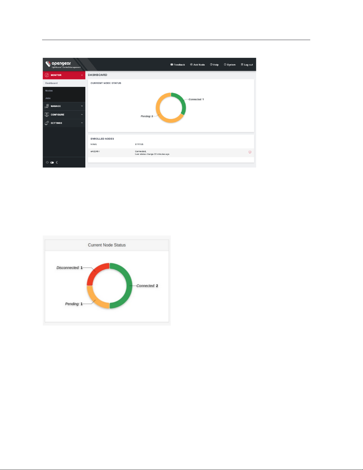
For root users, the Dashboard displays Enrolled Nodes, Cellular Health Status, Current Node Status, and
Licensing Information.
Cellular Health is clickable and will take you to the MANAGE > NODES > Node Web UI page where you
can view the Cellular Health column with information on each node.
Current Node Status is clickable. Nodes may be Connected, Disconnected, or Pending.
Clicking on:
• Pending opens CONFIGURE > NODE ENROLLMENT > Pending Nodes
• Connected opens CONFIGURE > NODE ENROLLMENT > Enrolled Nodes
• Disconnected opens MANAGE > NODES > Node Web UI filtered to show only disconnected nodes
NOTE: The appearance of the Dashboard, the sidebar, and other Lighthouse pages depends on the
privileges assigned to the currently logged in user. In this guide, screenshots represent what the root user
sees. Users with different privileges will see filtered views of available nodes, managed devices, users,
groups, tags, and Smart Groups have different privileges with regards to creating and changing settings
within Lighthouse.
Page 33
33
Lighthouse User Guide
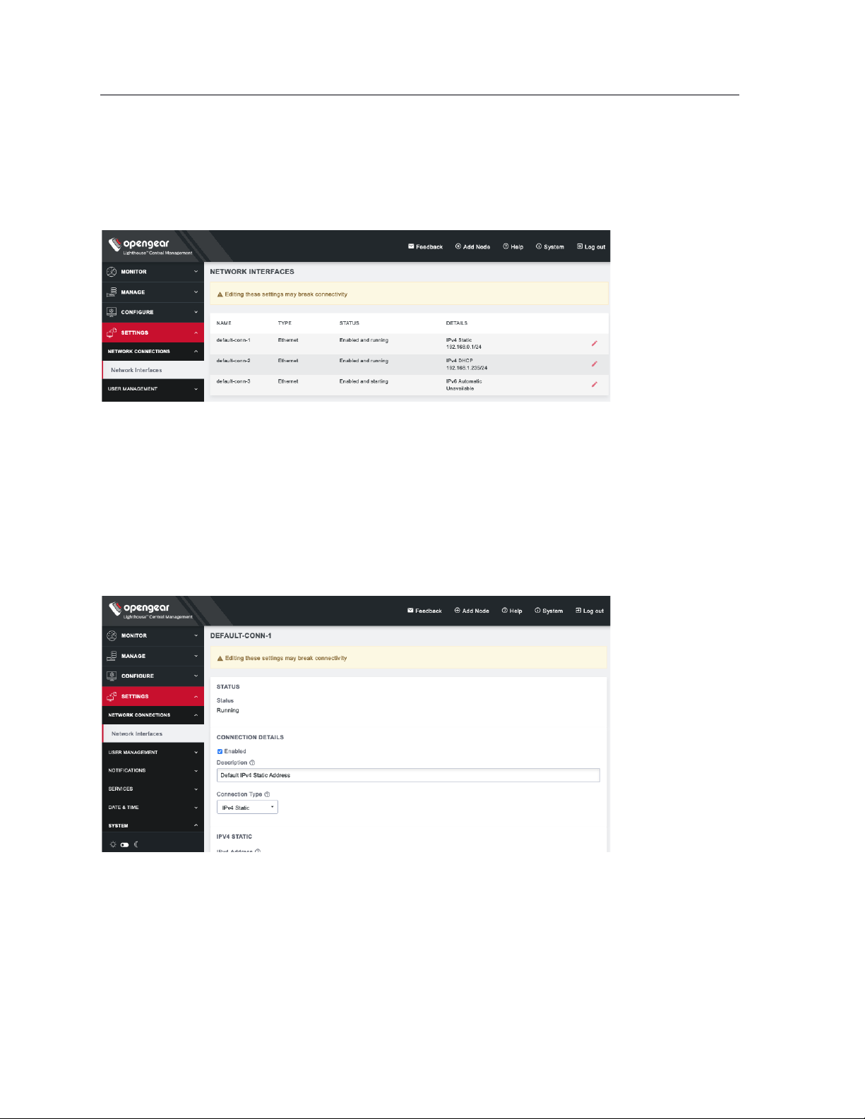
5.4 Network connections
To see the network connections available to Lighthouse, select SETTINGS > NETWORK CONNECTIONS >
Network Interfaces
This displays three connections: static and DHCP IPv4 interfaces and by default, an automatic IPv6
connection.
To edit a given network interface:
1. Select SETTINGS > NETWORK CONNECTIONS > Network Interfaces
2. Click the Edit icon to the right of the network interface to be modified.
3. Make the desired changes.
4. Click Apply.
NOTE: Don’t change the configuration method. Instead, disable the interface which will not be
used by unchecking the Enabled checkbox. If default-static and default-DHCP are changed to the
same configuration method (i.e. both are set to Static assignment or both are set to DHCP)
neither interface works.
Page 34
34
Lighthouse User Guide
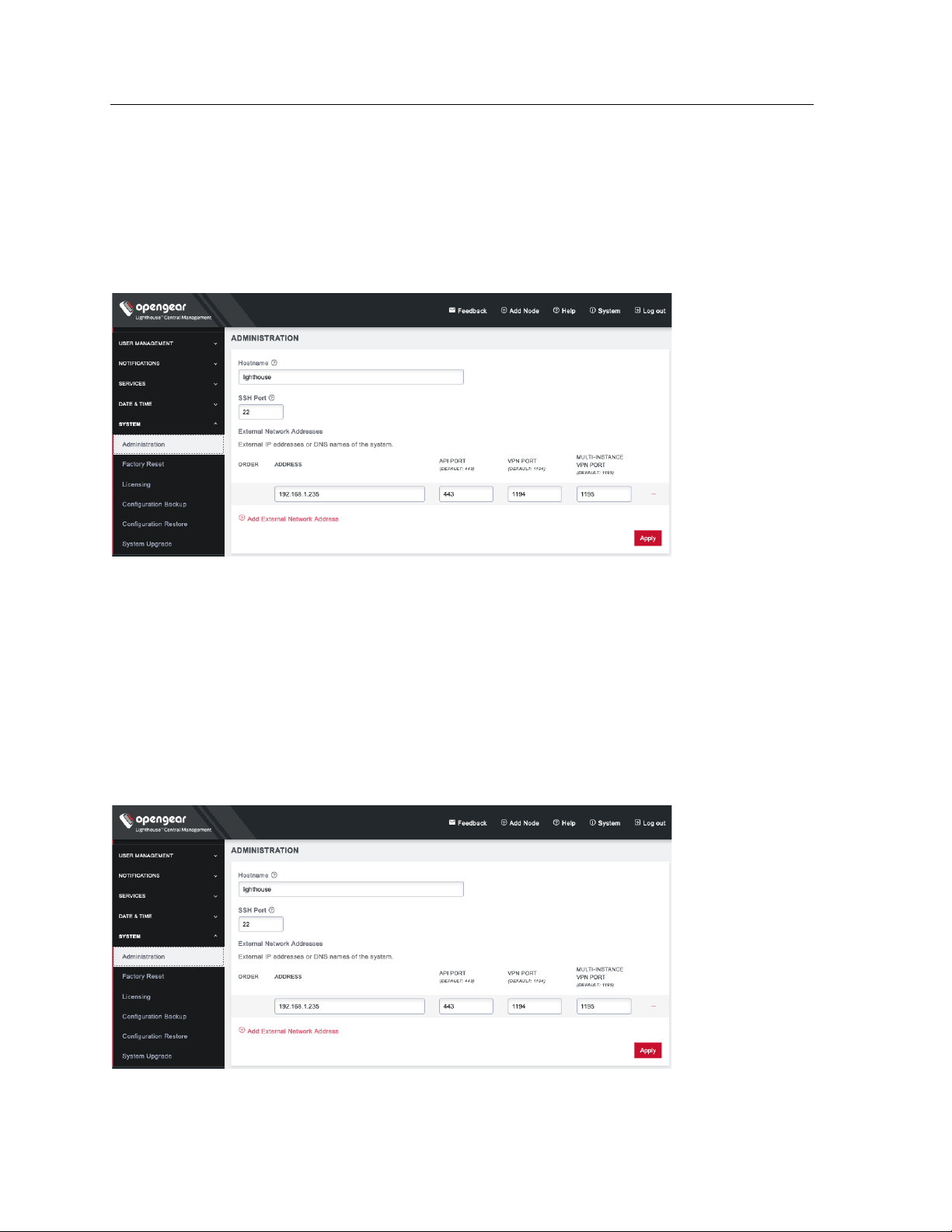
5.5 Setting the Lighthouse hostname
To set the hostname for a running Lighthouse instance:
1. Select SETTINGS > SYSTEM > Administration.
2. Edit the Hostname field as desired.
3. Click Apply.
5.6 Adding external IP addresses manually
Adding a Lighthouse instance’s external IP address or addresses to a Lighthouse instance’s configuration
is an optional step.
To add a single external address:
1. Select SETTINGS > SYSTEM > Administration.
2. In the Address field of the External Network Addresses section, enter an IP address.
Page 35
35
Lighthouse User Guide
3. Change the API Port, VPN Port, or Multi-Instance VPN Port if the ports used on the entered IP
address are different from the default settings.
4. Click Apply.
To add further external addresses to a Lighthouse instance’s configuration:
1. Click the + button. A second row appears in the External Network Addresses section.
2. In the Address field, enter an IP address.
3. Change the API Port, VPN Port, or Multi-Instance VPN Port if the ports used on the entered IP
address are different from the default settings.
4. Click Apply.
To change the order in which manually added IP addresses are sent to remote nodes:
1. Click the up and down arrows in the Order column to change the order in which the IP addresses
are listed.
2. Click Apply.
If external IP addresses are manually added to a Lighthouse configuration, these addresses are sent to a
remote node during enrollment. If no external IP address is manually added, default external IP addresses
are used.
The external IP addresses are sent to a remote node during enrollment in the following order:
1. net1:dhcp
2. net1:static1
3. The IP address connected to the default gateway.
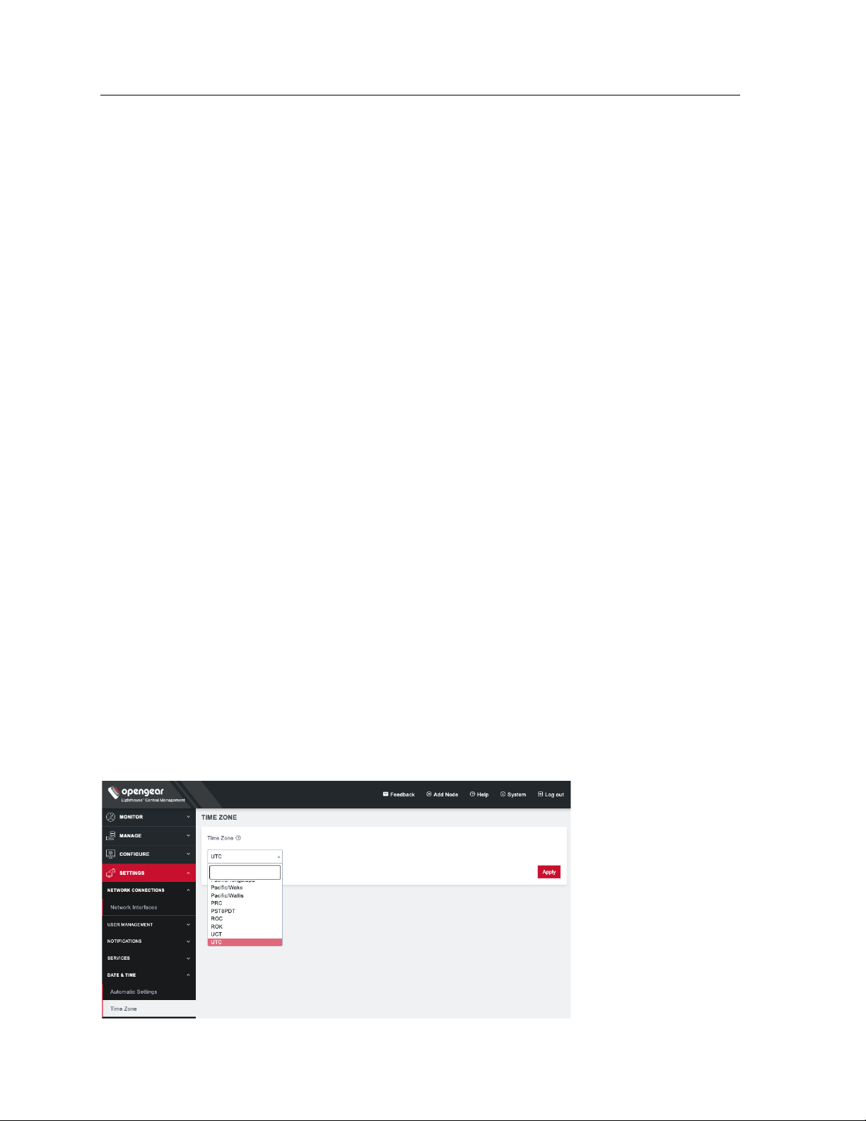
5.7 Setting the Lighthouse internal clock
To set the time zone:
1. Select SETTINGS > DATE & TIME > Time Zone.
2. Select the Lighthouse instance’s time-zone from the Time Zone drop-down list.
3. Click Apply.
Page 36
36
Lighthouse User Guide
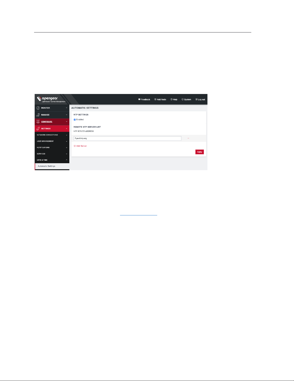
To use an NTP Server to automatically manage date and time:
1. Select SETTINGS > DATE & TIME > Automatic Settings.
2. Click the Enabled checkbox.
3. Click on + Add Server.
4. Enter a working NTP Server address in the NTP Server Address field.
5. Click Apply.
5.8 Examine or modify the Lighthouse SSL certificate
Lighthouse ships with a private SSL Certificate that encrypts communications between it and the
browser.
NOTE: If you plan to use the Lighthouse multiple instance feature, the certificate will be used on all
instances. In this case, we recommend using a wildcard certificate.
To examine this certificate or generate a new Certificate Signing Request, select SETTINGS > SERVICES >
HTTPS Certificate. The details of the Current SSL Certificate appear.
Below this listing is a Certificate Signing Request form, which can be used to generate a new SSL
certificate.
Page 37
37
Lighthouse User Guide
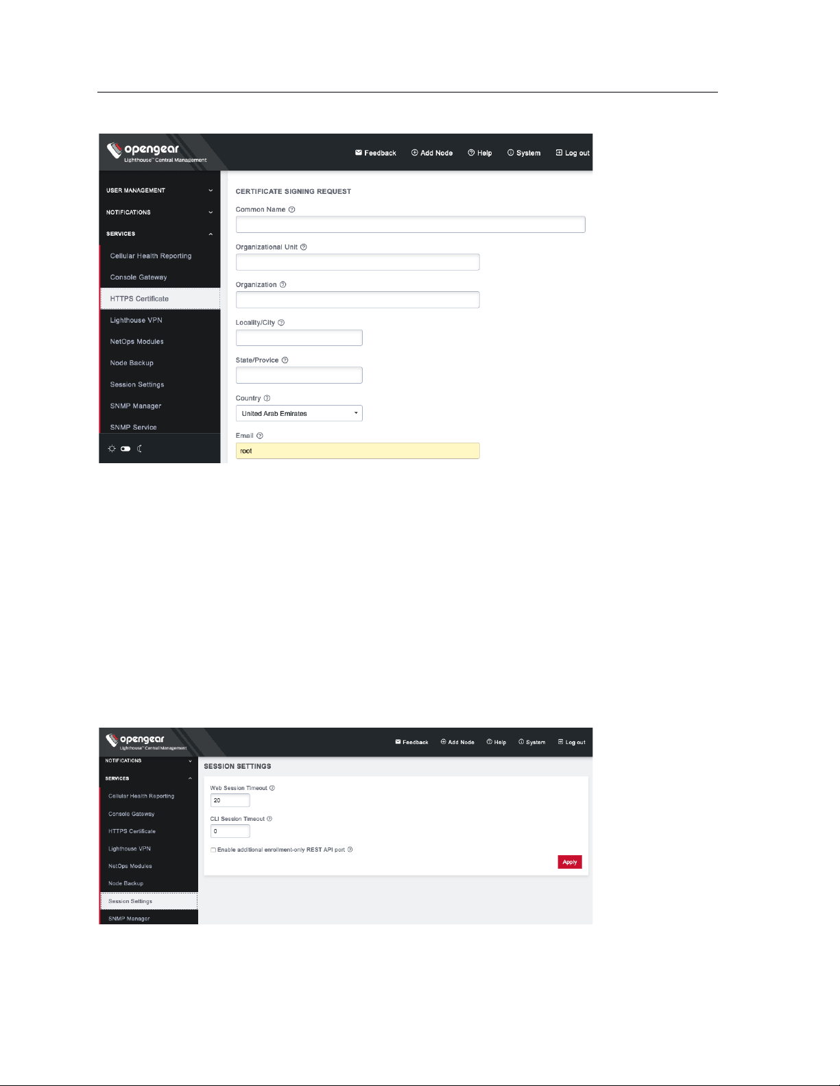
5.9 Examine or modify Lighthouse Session Settings
To modify Web and CLI session settings select SETTINGS > SERVICES > Session Settings.
• Web Session Timeout: This value can be set from 1 to 1440 minutes.
• CLI Session Timeout: This value can be set from 1 to 1440 minutes or set it to 0 to disable the
timeout. Changes take effect the next time a user logs in via the CLI.
• Enable additional enrollment-only REST API port: This port defaults to 8443. When this option is
enabled, only /nodes endpoint is accessible via port 8443(GET/POST/PUT) and all other
endpoints return a 404 Not Found error. Enabling this API allows users who are using NAT for the
Lighthouse to expose an external port publicly only for nodes that are attempting to enroll to the
Lighthouse, and not for the other functionality available from the REST API. After this option is
disabled, all endpoints should be accessible as per normal usage.
Page 38
38
Lighthouse User Guide
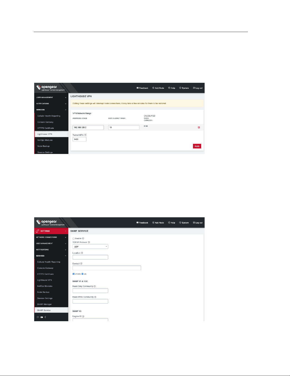
5.10 Examine or change the MTU of the Lighthouse VPN tunnel
The MTU setting can be configured for traffic that is travelling through the Lighthouse VPN in an attempt
to solve MTU path discovery problems. To modify the MTU of the Lighthouse VPN tunnel select
SETTINGS > SERVICES > Lighthouse VPN. Allowed values are between 1280 and 1500.
5.11 Enable or modify SNMP Service
Administrative users can configure SNMP settings under SETTINGS > SERVICES > SNMP Service.
Lighthouse supports both v1/v2 and v3 SNMP versions, which can be running at the same time. The
SNMP service is not enabled by default and starts once it has been configured correctly. If the user does
not provide an Engine ID, the auto-generated ID coming out of snmpd is displayed. Only standard
enterprise MIBs can be used. Lighthouse Health statistics (load/uptime/memory usage, etc.) can be
retrieved.
To enable SNMP Service,
Page 39
39
Lighthouse User Guide
1. Select the Enable checkbox.
2. Choose from the v1/v2c and v3 checkboxes.
3. Fill in the appropriate information for the SNMP versions.
4. Click Apply.
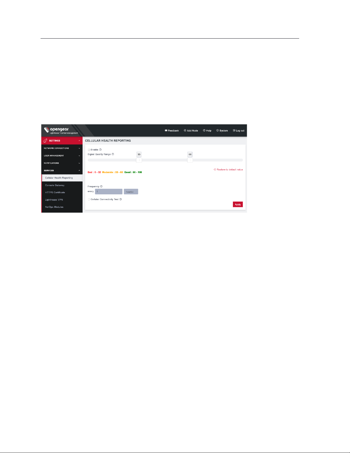
5.12 Cellular Health Settings
Administrative users can control the cellular health reporting settings under SETTINGS > SERVICES >
Cellular Health Reporting.
• Check the Enable box to enable Cellular Health monitoring.
• Adjust the sliders on this screen to control what you consider Good, Bad, and Moderate signal
quality to be. This will change the Cellular Health information displayed in various node lists and
on the Dashboard.
• Adjust how frequently Lighthouse will check the signal quality.
• Finally, you can run a periodic Cellular Connectivity Test which will make sure the cellular can
actually connect. This will use cellular data.
NOTE: Cellular Health Reporting requires Console Server firmware version 4.5 or greater.
5.13 Lighthouse MIBs
Lighthouse MIBs can be found in /usr/share/snmp/mibs/.
Lighthouse can be configured to expose managed node information such as node name, node model
number, node port label, license status, etc. via SNMP.
Some generic information about Lighthouse version and nodes count can be found at:
ogLhStatus:
ogLhVersion
ogLhNodes
ogLhNodesTotal
ogLhNodesPending
ogLhNodesConnected
ogLhNodesDisconnected
ogLhNodesTable with detailed information about nodes.
For enrolled Opengear node, the following information is available.
Page 40

40
Lighthouse User Guide
ogLhNodesTable:
ogLhNodeIndex
ogLhNodeName
ogLhNodeModel
ogLhNodeProductType
ogLhNodeVpnAddress
ogLhNodeSerialNumber
ogLhNodeUptime
ogLhNodeConnStatus
ogLhNodePortsTable:
ogLhPortIndex
ogLhPortLabel
ogLhPortID
ogLhNodeInterfacesTable:
ogLhNodeInterfaceIndex
ogLhNodeInterfaceName
ogLhNodeInterfaceAddress
For enrolled third-party node, the following information is available:
ogLhThirdPartyNodesTable:
ogLhThirdPartyNodeIndex
ogLhThirdPartyNodeSSHPort
ogLhThirdPartyNodeName
ogLhThirdPartyNodeModel
ogLhThirdPartyNodeProductType
ogLhThirdPartyNodeAddress
ogLhThirdPartyNodeSerialNumber
ogLhThirdPartyNodeUptime
ogLhThirdPartyNodeConnStatus
ogLhThirdPartyNodePortsTable:
ohLhThirdPartyPortIndex
ogLhThirdPartyPortLabel
ogLhThirdPartyPortConnectionMethod
ogLhThirdPartyPortMode
ogLhThirdPartyRemotePort
ogLhThirdPartyPortLineID
You can query for licensing information.
ogLhLicenseStatus:
ogLhLicInstalled
ogLhLicSupported
ogLhLicExpiry
ogLhLicStatus
ogLhLicFeatureName
You can also query for enrolled node cellular health information.
ogLhNodeCellularHealth
SNMP commands such as snmpwalk or snmpget retrieve Lighthouse specific information.
Setup: SNMP is configured with version 1 and public is community string
Page 41

41
Lighthouse User Guide
Lighthouse public IP address is 192.168.1.1
All MIBs, including Lighthouse MIB are available in /usr/share/snmp/mibs
Below are some examples of Lighthouse MIB queries using SNMP:
Walk through the entire ogLighthouseMib using name:
snmpwalk -m ALL -v1 -c public 192.168.1.1 ogLighthouseMib
snmpwalk -m ALL -M /usr/share/snmp/mibs -v1 -c public 192.168.1.1
ogLighthouseMib
Walk through the entire ogLighthouseMib using the OID directly:
snmpwalk -m ALL -M /usr/share/snmp/mibs -v1 -c public 192.168.1.1
1.3.6.1.4.1.25049.18.1
Get the total nodes enrolled in Lighthouse:
snmpget -m ALL -v1 -c public 192.168.1.1 ogLhNodesTotal.0
snmpwalk -m ALL -v1 -c public 192.168.1.1 ogLhNodesTotal
Get serial number with enrolled node having VPN address 192.168.128.2:
snmpwalk -m ALL -v1 -c public 192.168.1.1 ogLhNodeSerialNumber.192.168.128.2
snmpget -m ALL -v1 -c public 192.168.1.1 ogLhNodeSerialNumber.192.168.128.2
Get cellular health for all enrolled nodes:
snmpwalk -m ALL -c public -v 1 192.168.124.143 ogLhNodeCellularHealth
OG-LIGHTHOUSE-MIB::ogLhNodeCellularHealth.192.168.128.2 = INTEGER: good(4)
OG-LIGHTHOUSE-MIB::ogLhNodeCellularHealth.192.168.128.3 = INTEGER: good(4)
OG-LIGHTHOUSE-MIB::ogLhNodeCellularHealth.192.168.128.4 = INTEGER: bad(2)
OG-LIGHTHOUSE-MIB::ogLhNodeCellularHealth.192.168.128.5 = INTEGER: unknown(0)
OG-LIGHTHOUSE-MIB::ogLhNodeCellularHealth.192.168.128.6 = INTEGER: bad(2)
5.14 SNMP Manager Settings
Administrative users can configure the SNMP Manager settings. Select SETTINGS > SERVICES > SNMP
Manager. The SNMP Manager allows SNMP TRAP/INFORM messages to be sent from Lighthouse to a
configured server any time a node connection status is changed.
Page 42

42
Lighthouse User Guide
To enable the SNMP Manager,
1. Under the Settings section, select the Enable checkbox.
2. Choose UDP, UDP over IPv6, TCP, or TCP over IPv6 in the Manager Protocol drop-down.
3. Enter the Manager Address to receive SNMP messages.
4. Enter the Manager Port.
5. Check the SNMP protocol Version from the v1, v2c, v3 drop-down.
Depending on the selected SNMP version, complete the following steps.
For v1, enter the SNMP Community to use for messages.
For v2c:
1. Choose TRAP or INFORM as the SNMP Message Type.
2. Enter the SNMP Community to use for messages.
For v3:
1. Choose TRAP or INFORM as the SNMP Message Type.
2. Specify an optional Engine ID for sending an SNMP TRAP message. If left blank, the auto-
generated Engine ID from the SNMP Service will be used. An Engine ID is not needed for an
SNMP INFORM message.
3. Enter the SNMP v3 Engine ID and desired Security Level.
4. Enter the Username to send the messages as, select the Authentication Protocol, either MD5 or
SHA, and enter the SNMP user’s Authentication Password.
5. Choose a Privacy Protocol, either DES or AES, and enter a Privacy Password.
Page 43

43
Lighthouse User Guide
For all three SNMP versions, trigger TRAP/INFORM notifications by checking either or both of the Node
Connection Status and the Node Cellular Heath Status checkboxes. Click Apply.
When a node connection status changes, a nodeStatusNotif notification is sent, populated with data
about the node's connection status, address and name.
Structure of notifications for Opengear nodes:
nodeStatusNotif
ogLhNodeName
ogLhNodeIndex
ogLhNodeConnStatus
Structure of notifications for third-party nodes:
thirdPartyNodeStatusNotif
ogLhThirdPartyNodeIndex
ogLhThirdPartyNodeName
ogLhThirdPartyNodeAddress
ogLhThirdPartyNodeConnStatus
5.15 Syslog export
Page 44

44
Lighthouse User Guide
Administrative users can specify multiple external servers to export the syslog to via TCP or UDP. Select
SETTINGS > SERVICES > Syslog.
This page lists any previously added external syslog servers. To add a new one,
1. Click the + symbol. The Add External Syslog Server dialog opens.
2. Enter the Server Address.
3. Enter the Protocol, either UDP or TCP.
4. Enter the correct Port. If no port is entered, UDP defaults to port 514 and TCP defaults to 601.
5. Click Apply.
To edit an existing syslog server, click the Edit button . Delete a server by clicking the x button .
Page 45

45
Lighthouse User Guide
Here are a few examples of what lines in the syslog look like:
Edit the user “fred” and make him a member of the admin group
2020-05-22T16:22:40.646116+01:00 LH20Q3-pre rest_api_log[2513]: GET 200 (root |
192.168.1.230) - /api/v3.5/groups?page=1&per_page=99
2020-05-22T16:22:46.403616+01:00 localhost rest_api_log[62]: PUT 200 (root |
192.168.1.230) - /api/v3.5/users/users-2 REQUEST={'user': {'username': 'fred',
'password': '********', 'description': 'fred', 'enabled': True, 'groups': ['groups2'], 'rights': {'delete': True, 'modify': True}, 'no_password': False, 'expired':
False, 'locked_out': False}} RESPONSE={'user': {'username': 'fred', 'description':
'fred', 'enabled': True, 'id': 'users-2', 'no_password': False, 'expired': False,
'locked_out': False, 'rights': {'delete': True, 'modify': True}, 'groups': ['groups2']}}
2020-05-22T16:22:46.490627+01:00 localhost rest_api_log[62]: GET 200 (root |
192.168.1.230) - /api/v3.5/users?page=1&per_page=10 RESPONSE={'users': [{'username':
'root', 'description': 'System wide SuperUser account', 'enabled': True, 'id': 'users1', 'no_password': False, 'expired': False, 'locked_out': False, 'rights': {'delete':
True, 'modify': True}, 'groups': ['groups-2']}, {'username': 'fred', 'description':
'fred', 'enabled': True, 'id': 'users-2', 'no_password': False, 'expired': False,
'locked_out': False, 'rights': {'delete': True, 'modify': True}, 'groups': ['groups2']}], 'meta': {'total_pages': 1}}
Disable the user “fred”
2020-05-22T16:24:11.626425+01:00 localhost rest_api_log[62]: PUT 200 (root |
192.168.1.230) - /api/v3.5/users/users-2 REQUEST={'user': {'username': 'fred',
'password': '********', 'description': 'fred', 'enabled': False, 'groups': ['groups2'], 'rights': {'delete': True, 'modify': True}, 'no_password': False, 'expired':
False, 'locked_out': False}} RESPONSE={'user': {'username': 'fred', 'description':
'fred', 'enabled': False, 'id': 'users-2', 'no_password': False, 'expired': False,
'locked_out': False, 'rights': {'delete': True, 'modify': True}, 'groups': ['groups2']}}
Enable the user “fred”
2020-05-22T16:25:08.013266+01:00 localhost rest_api_log[62]: PUT 200 (root |
192.168.1.230) - /api/v3.5/users/users-2 REQUEST={'user': {'username': 'fred',
'password': '********', 'description': 'fred', 'enabled': True, 'groups': ['groups2'], 'rights': {'delete': True, 'modify': True}, 'no_password': False, 'expired':
False, 'locked_out': False}} RESPONSE={'user': {'username': 'fred', 'description':
'fred', 'enabled': True, 'id': 'users-2', 'no_password': False, 'expired': False,
'locked_out': False, 'rights': {'delete': True, 'modify': True}, 'groups': ['groups2']}}
2020-05-22T16:25:08.236626+01:00 LH20Q3-pre configurator_users[21644]: User <fred>
added to passwords file
Change the user “fred's” password
Page 46

46
Lighthouse User Guide
2020-05-22T16:29:41.698685+01:00 localhost rest_api_log[62]: PUT 200 (root |
192.168.1.230) - /api/v3.5/users/users-2 REQUEST={'user': {'username': 'fred',
'password': '********', 'description': 'fred', 'enabled': True, 'groups': ['groups2'], 'rights': {'delete': True, 'modify': True}, 'no_password': False, 'expired':
False, 'locked_out': False}} RESPONSE={'user': {'username': 'fred', 'description':
'fred', 'enabled': True, 'id': 'users-2', 'no_password': False, 'expired': False,
'locked_out': False, 'rights': {'delete': True, 'modify': True}, 'groups': ['groups2']}}
2020-05-22T16:29:41.866376+01:00 localhost rest_api_log[62]: GET 200 (root |
192.168.1.230) - /api/v3.5/users?page=1&per_page=10 RESPONSE={'users': [{'username':
'root', 'description': 'System wide SuperUser account', 'enabled': True, 'id': 'users1', 'no_password': False, 'expired': False, 'locked_out': False, 'rights': {'delete':
True, 'modify': True}, 'groups': ['groups-2']}, {'username': 'fred', 'description':
'fred', 'enabled': True, 'id': 'users-2', 'no_password': False, 'expired': False,
'locked_out': False, 'rights': {'delete': True, 'modify': True}, 'groups': ['groups2']}], 'meta': {'total_pages': 1}}
5.16 Node Backup
NOTE: Node backup requires firmware 4.6 or later.
Administrative users can enable automatic node backup. Up to 10 backups can be stored on a rolling
basis.
1. Select SETTINGS > SERVICES > Node Backup.
2. Click the Enable checkbox to turn on this service.
Page 47

47
Lighthouse User Guide
3. Under the Storage section, choose the Number of stored backups you wish to keep.
4. Choose how long you wish these backups to be stored after unenrollment. Selecting Days opens
a field that allows you to enter a number.
5. Enter the Location you wish to store the backup files. We suggest you store backups at
/mnt/nvram/.
6. Click Validate to make sure the location exists and has enough space to store them.
7. Click Apply or set a schedule.
To set an automated schedule for performing node backups:
1. Scroll down to the Scheduling section.
2. For the Start time, choose either Immediately or choose Set Time to open editable Date and Time
fields.
3. Choose how often you wish to Repeat the backup by adjusting the values for Interval.
NOTE: You can modify these options by returning to SETTINGS > SERVICES > Node Backup at any
time.
5.17 Monitor Nodes
Lighthouse allows you to view all nodes including connected, not connected, enrolled, and pending, as
well as nodes using cellular. Go to MONITOR > Nodes.
This page displays the cellular health and number of ports. It also offers a button on the right of
connected nodes to access the Web UI.
To the right of the table, you can filter by Smart Group, connection status, and perform a text search. By
default, the Show all filter is selected.
Page 48
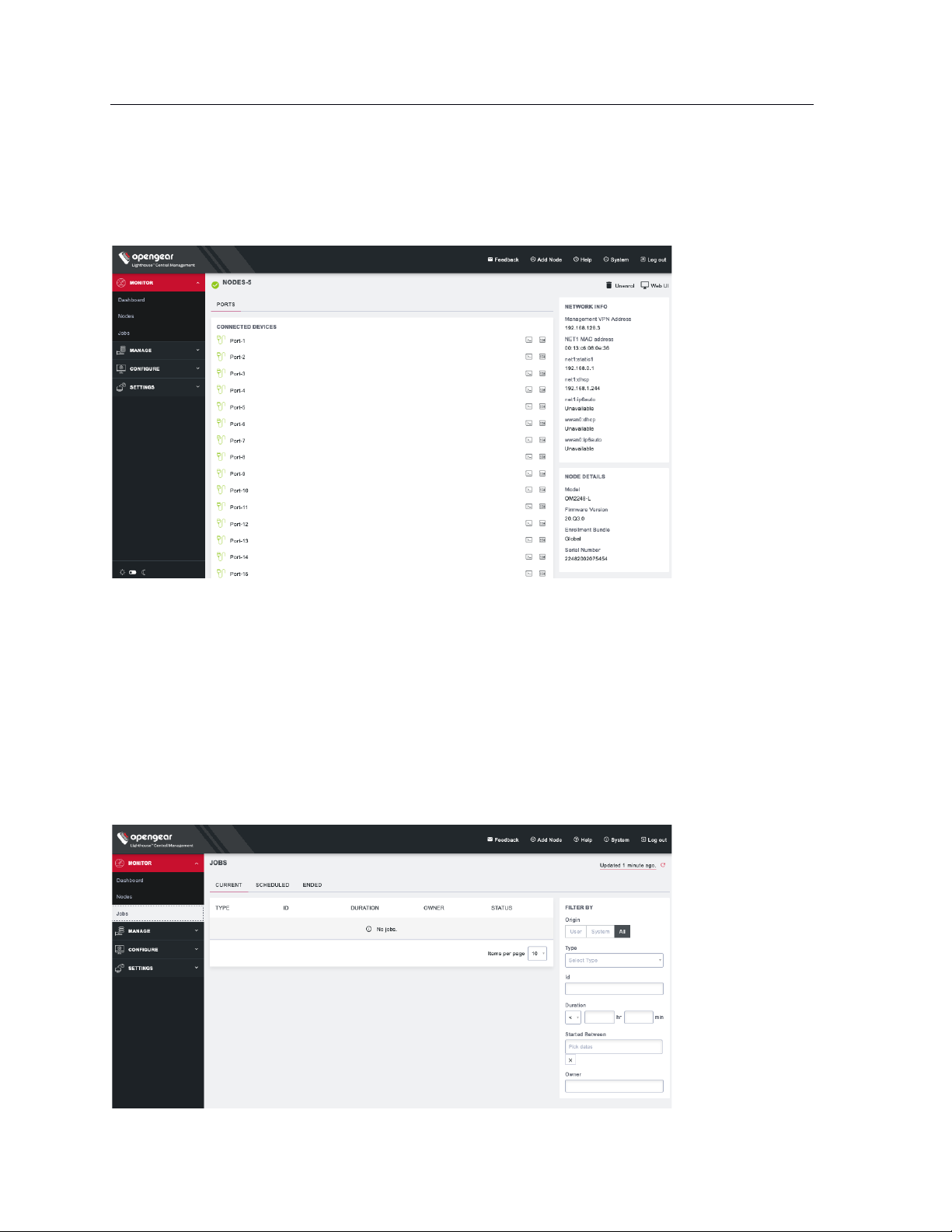
48
Lighthouse User Guide
You can click on any connected node to view the node details, list of connected devices, and a list of
unconfigured ports. From this detail page, you can access the web terminal and SSH of each connected
device. You can also unenroll a connected node or visit the Web UI using the buttons on the top right of
the page.
5.18 Monitor Jobs
You can keep track of jobs in Lighthouse which are scheduled, running, or have run.
NOTE: For the 20.Q4.0 release, this can only monitor system-created jobs. Future releases will add
increased functionality.
Go to MONITOR > Jobs.
Page 49

49
Lighthouse User Guide
At the top of the page, you can click on CURRENT, SCHEDULED, or ENDED links to see those jobs. You
can also use the FILTER BY form on the right to further refine your results by type, ID, job duration, dates
the job began, and owner.
Page 50
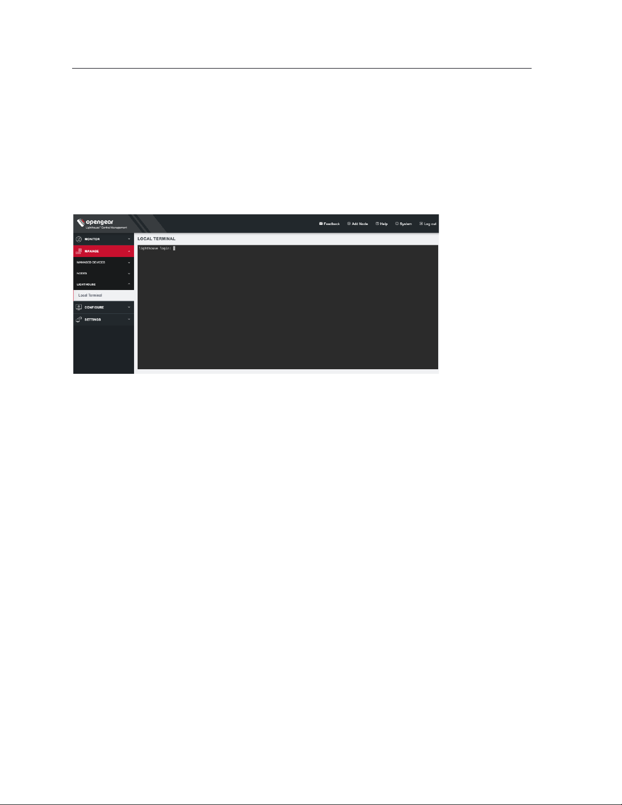
50
Lighthouse User Guide
6. Shut Down or Restart Lighthouse
6.1 Shut down a running Lighthouse instance
To shut down a running Lighthouse instance:
1. Select MANAGE > LIGHTHOUSE > Local Terminal
2. At the Local Terminal login prompt enter a username with administrative privileges (e.g. root).
3. At the Password: prompt, enter that account’s password. A Last login date and time for that
account are returned to STD OUT and a shell prompt for the logged in user appears.
4. Enter the command shutdown now and press Return. The virtual machine shuts down.
6.2 Restarting a running Lighthouse instance
To restart a running Lighthouse instance, follow the first three steps of the Shutting down a running
Lighthouse instance procedure above. At the shell prompt, enter one of these commands and press
Return:
• reboot
• shutdown -r now
The Lighthouse virtual machine shuts down and reboots.
7. Using Lighthouse
After Lighthouse has been installed and configured, a small set of nodes should be enrolled, and a set of
tags and smart groups should be created that allow nodes access to be filtered to the correct subset of
users.
Once these nodes are installed, access to the Node’s Web UI and serial ports should be tested.
This section covers:
Page 51
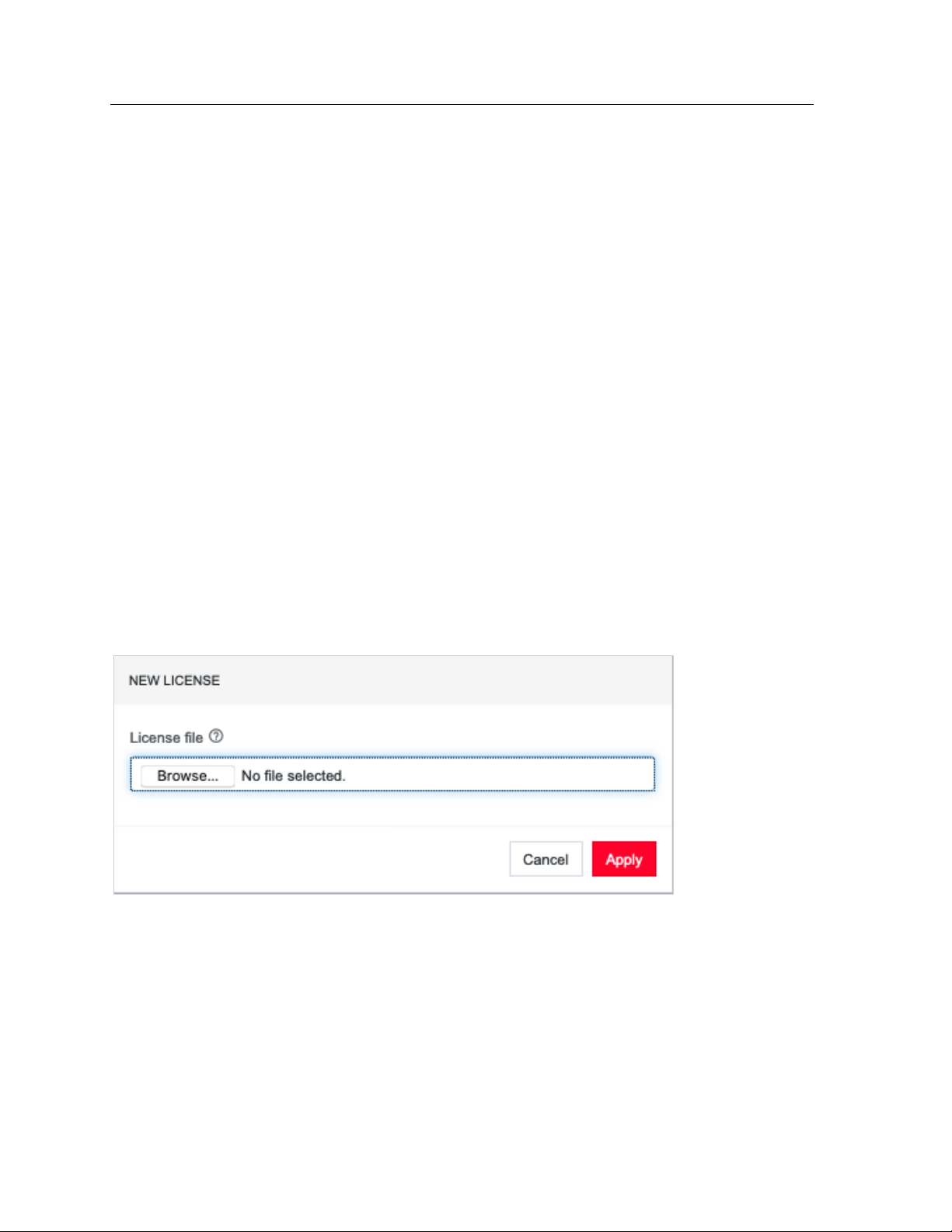
51
Lighthouse User Guide
• Licensing third-party nodes before enrollment
• Enrolling nodes
• The Enrolled Nodes page
• Filtering pages displaying nodes
• Creating and editing Smart Groups
• Creating and editing Managed Device Filters
• Connecting to a node’s web management interface
• Connecting to a node’s serial ports via Console Gateway
7.1 Licensing third-party nodes before enrollment
Lighthouse includes support for managing third-party remote nodes at no cost. Support for third-party
remote nodes is not built-in to a new Lighthouse instance, however: it is added via a license.
A license is an encrypted, RFC 7519-compliant, JSON web token that contains key-values. Licenses are
distributed by Opengear and are available as .zip files by e-mail via a fulfillment procedure.
Before enrolling a third-party remote node, its corresponding license must be added to Lighthouse as
follows:
7.1.1 Adding a license using the Lighthouse UI
1. Select SETTINGS > SYSTEM > Licensing
2. Click the + button at the top of the page. A New License dialog opens.
3. Click Browse… to select the license file to upload.
4. Click Apply.
7.1.2 Showing installed licenses in the Lighthouse UI
To see all installed licenses, select SETTINGS > SYSTEM > Licensing.
Installed licenses are also shown on the Lighthouse dashboard under the LICENSING INFORMATION
section. Select MONITOR > Dashboard to open the Dashboard.
Page 52
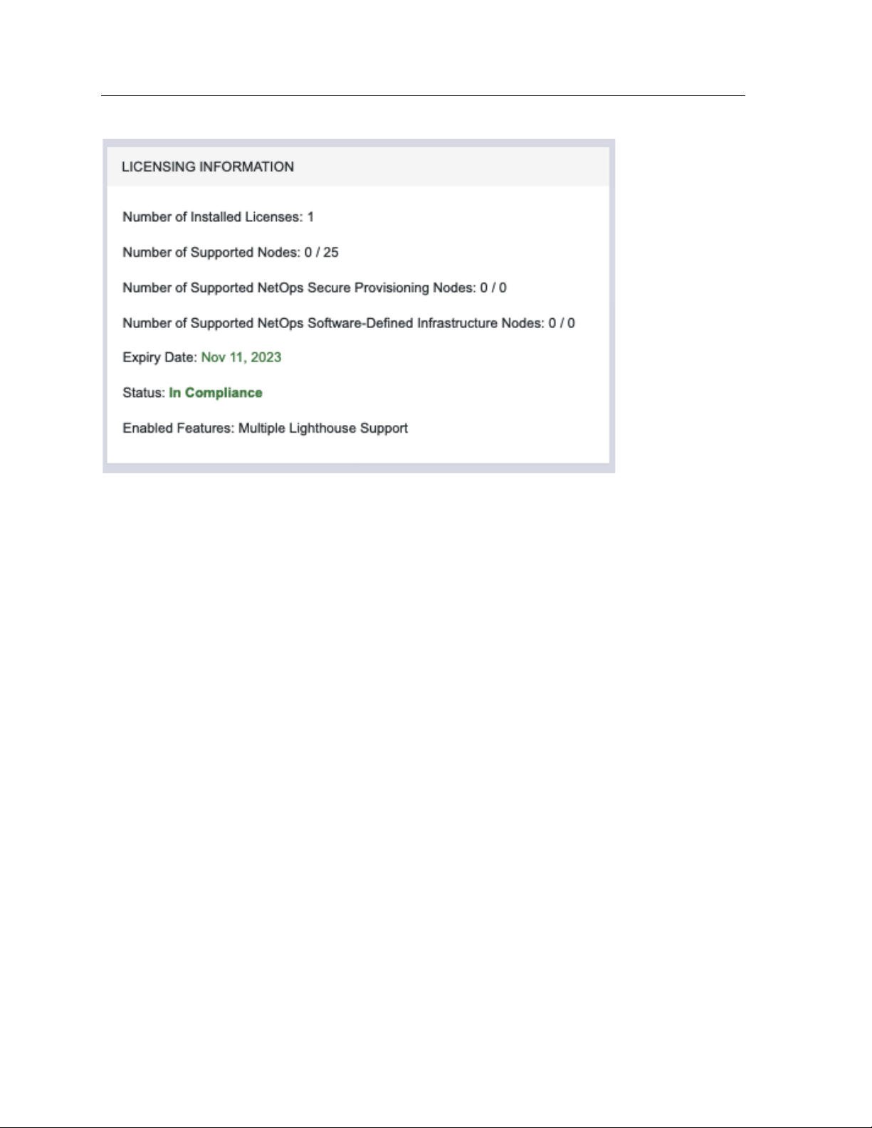
52
Lighthouse User Guide
The dashboard also displays messages when:
• The number of nodes supported by a license has been reached or exceeded.
• The maintenance period of a license has expired.
7.1.3 Showing installed licenses via the Local Terminal
oglicdump is a shell-based tool that writes the current licensing status of a Lighthouse instance to STD
OUT (or, using the -o switch, a file).
For example:
# oglicdump
{
"OGLH": {
"contact": {
"email": "test@test.com",
"name": "test",
"phone": "test"
},
"features": {
"additional": {
"multipleinstance": "1",
"thirdpartynodes": "1"
},
"maintenance": 1548806400,
"nodes": 20
}
}
}
If no licenses are installed, oglicdump returns the following:
Page 53

53
Lighthouse User Guide
# oglicdump
No data found
7.2 Enrolling nodes
7.2.1 Enrollment overview
Enrolling nodes is the process of connecting nodes to Lighthouse to make them available for access,
monitoring, and management. Enrollment can be performed via:
• The Lighthouse Web UI
• The Node Web UI
• ZTP
• USB key
Credentials must be provided to authenticate either the Lighthouse during enrollment via the Lighthouse
WebUI, or the node during the other enrollment scenarios.
The Lighthouse VPN uses certificate-authenticated OpenVPN tunnels between Lighthouse and remote
nodes. These tunnels rely on the time being synchronized between the Lighthouse instance and the
console server or other remote node. During enrollment, if a remote node is not relying on an NTP server
to set its time, it inspects the HTTP Date header sent by Lighthouse and sets its local time to match that
of the Lighthouse instance.
If a remote node is relying on an NTP server to set its own time, it still checks the HTTP Date header sent
by Lighthouse to affect the time synchronization but does not set its local time to that of the Lighthouse
instance.
When enrolling via Lighthouse, an administration username and password for the node must be provided.
When enrolling via the node, an enrollment token must be provided. A default enrollment token can be set
on the CONFIGURE > NODE ENROLLMENT > Enrollment Settings page, and individual tokens set per
enrollment bundle.
Enrollment is a two-step process:
1. Once enrollment starts, nodes receive their enrollment package, and establish a VPN connection
to Lighthouse.
2. The node is now in the Pending state and needs to be Approved before the node is available for
access, management, or monitoring.
NOTE: This second step can be skipped by selecting the Auto-approve node checkbox when
configuring an enrollment bundle.
7.2.2 Enrollment bundles
An enrollment bundle is a downloadable file that stores provisioning information, allowing for bulk
enrollment and manipulation of remote nodes.
Page 54
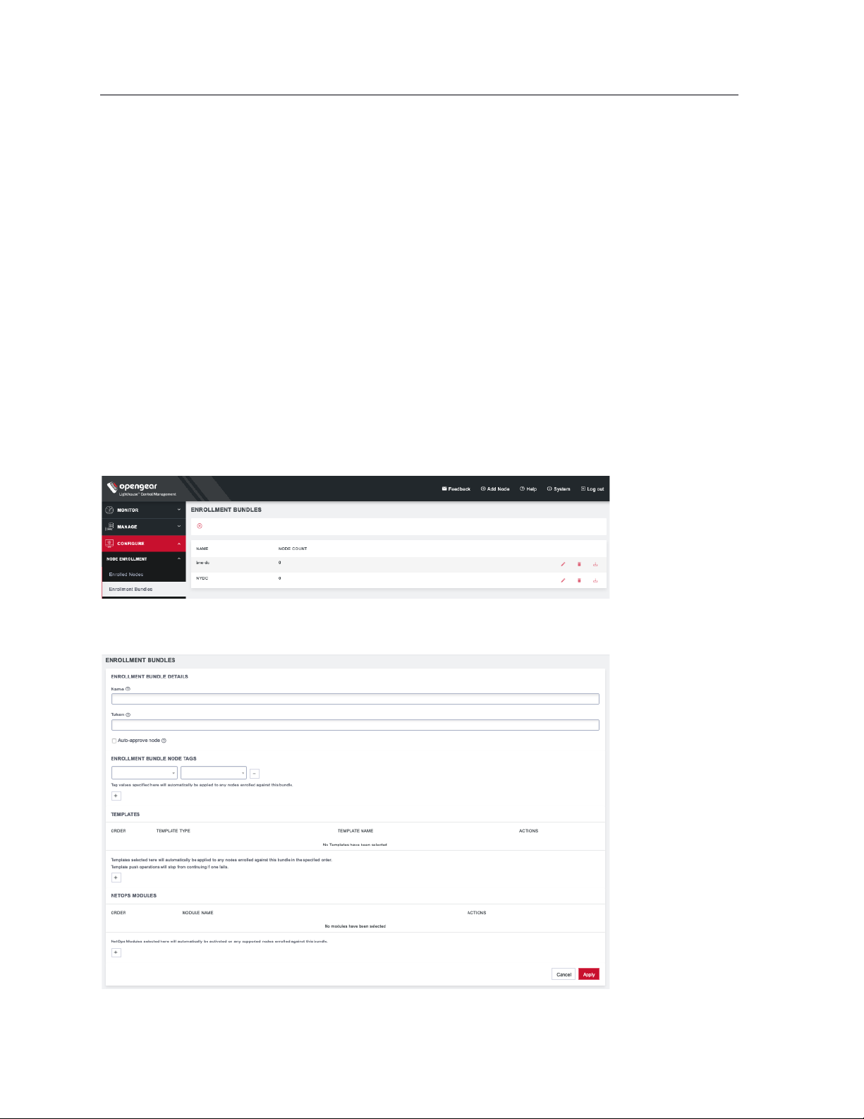
54
Lighthouse User Guide
Applying an enrollment bundle during enrollment allows tags to be associated with nodes when they’re
first enrolled, rather than manually assigning tags after the nodes are enrolled.
This is useful for larger roll outs where there are many nodes deployed with a similar configuration and
responsibilities. If relevant Smart Groups and tags have been set up, newly enrolled nodes are
immediately visible for the relevant users to configure and use.
Associating templates with an enrollment bundle allows to run a set of templates on a node, after it has
been enrolled. Any template defined on the Lighthouse can be added to an enrollment bundle, and each
bundle supports any number of templates.
NOTE: NetOps modules (see NetOps User Guide) can also be associated with enrollment bundles.
7.2.3 Creating an enrollment bundle
An enrollment bundle can be created in a Lighthouse instance as follows:
1. Select CONFIGURE > NODE ENROLLMENT > Enrollment Bundles
2. Click the + button. The Enrollment Bundle Details page appears.
Page 55
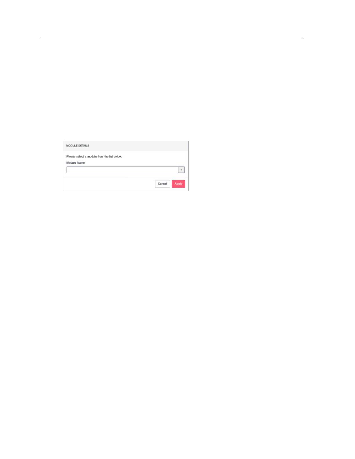
55
Lighthouse User Guide
3. Enter a Name and Authentication Token for the bundle in the respective fields.
4. Select the number of Tags and Values to apply to any nodes that enroll using this enrollment
bundle.
5. (Optional) Select the Auto-approve node checkbox.
When this is checked, a device configured using this enrollment bundle is not placed in pending
mode during the enrollment process. Instead, it is automatically approved for enrollment after it
has been identified.
6. You can also use this bundle to automatically activate NetOps modules for any supported nodes.
Scroll down to the NETOPS MODULES section and press the + button to open the MODULE
DETAILS dialog.
7. Select the desired Module Name from the drop-down list. Click Apply.
With the enrollment bundle named, use the ENROLLMENT BUNDLE NODE TAGS to populate it with the
desired name-value pairs:
1. Select a field name from the left-most drop-down menu.
2. Select or enter a value from the right-most drop-down menu.
3. Click the + button to add a new pair of drop-down menus.
4. Select another field name and select or enter another value.
5. Repeat until all desired name-value pairs are displayed.
6. Click Apply.
With the enrollment bundle named, use the TEMPLATES to populate it with the desired list of templates
to be applied post-enrollment:
1. Click the + button to add a new pair of drop-down menus.
2. Select a value from the Template Type menu. The selected template type filters the available
names to those templates of that type.
3. Select a value from the Template Name menu.
4. Repeat until all desired type-name pairs are displayed.
5. Click Apply.
6. The templates in the table can be reordered using the arrow buttons in the far-left column of the
table and are executed in the order they appear. The order buttons appear if there is more than
one template in the table.
Template push operations stop if one template fails.
7.2.4 Structure of an enrollment bundle
An enrollment bundle file, manifest.og, contains a series of field-value pairs that an unconfigured
device can use to configure itself.
Page 56
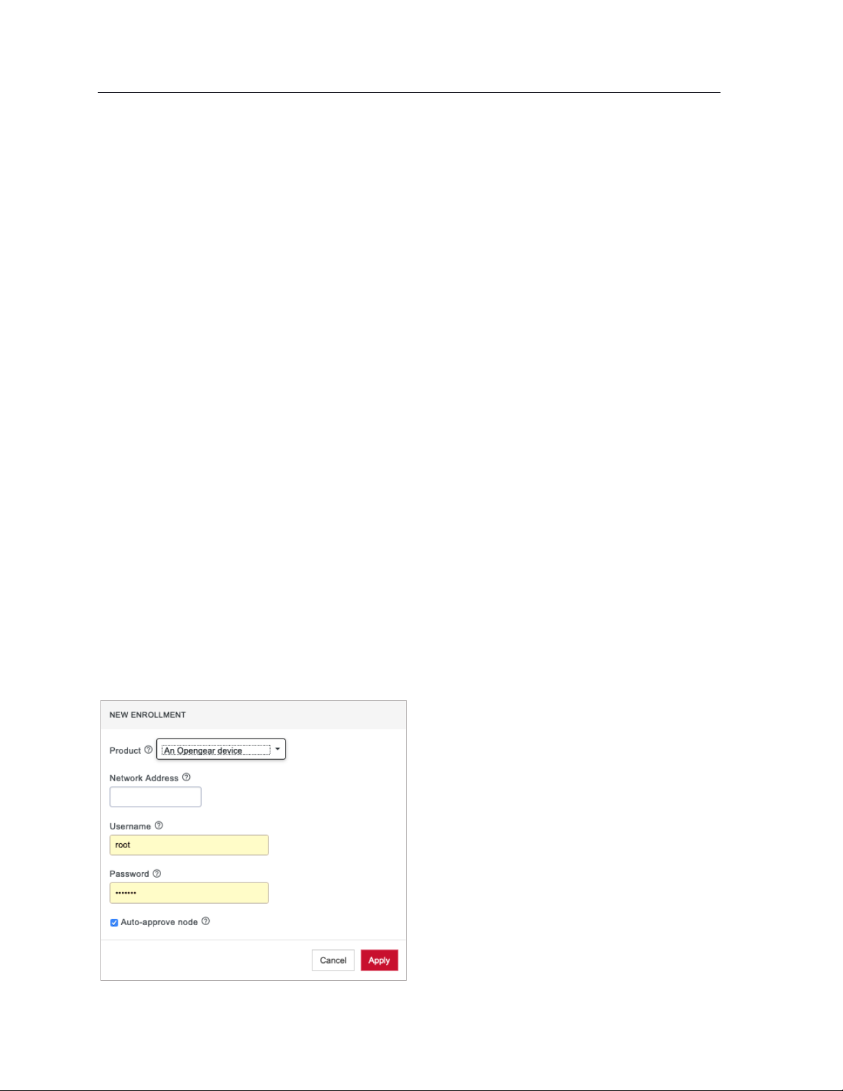
56
Lighthouse User Guide
Options that can be set in manifest.og include new firmware, custom configuration scripts, OPG config
files, and Lighthouse enrollment details.
By default, manifest.og includes the following field-value pairs (with example values):
address=192.168.88.20
api_port=4443
bundle=bne-dc
password=secret
Custom field-value pairs can be added manually. The field names are potential field names for a realworld, customized file, but the values following each field name are examples:
script=configure_ports.sh
image=acm7000-3.16.6.image
external_endpoints=192.168.1.2:4444,192.168.1.3:4445
7.2.5 Enrollment via Lighthouse Web UI
Enrollment via Lighthouse Web UI only works if the Node is reachable from Lighthouse.
1. Select the Add Node shortcut in the top menu bar to open a NEW ENROLLMENT dialog.
2. Select the Product type from the Product drop-down menu.
3. Available options in the Product drop-down menu are:
• An Opengear device
• A generic third-party device
• An Avocent ACS6000
• An Avocent ACS8000
• An Avocent ACS Classic
• A Cisco 2900 Series
• A Digi Passport
Page 57
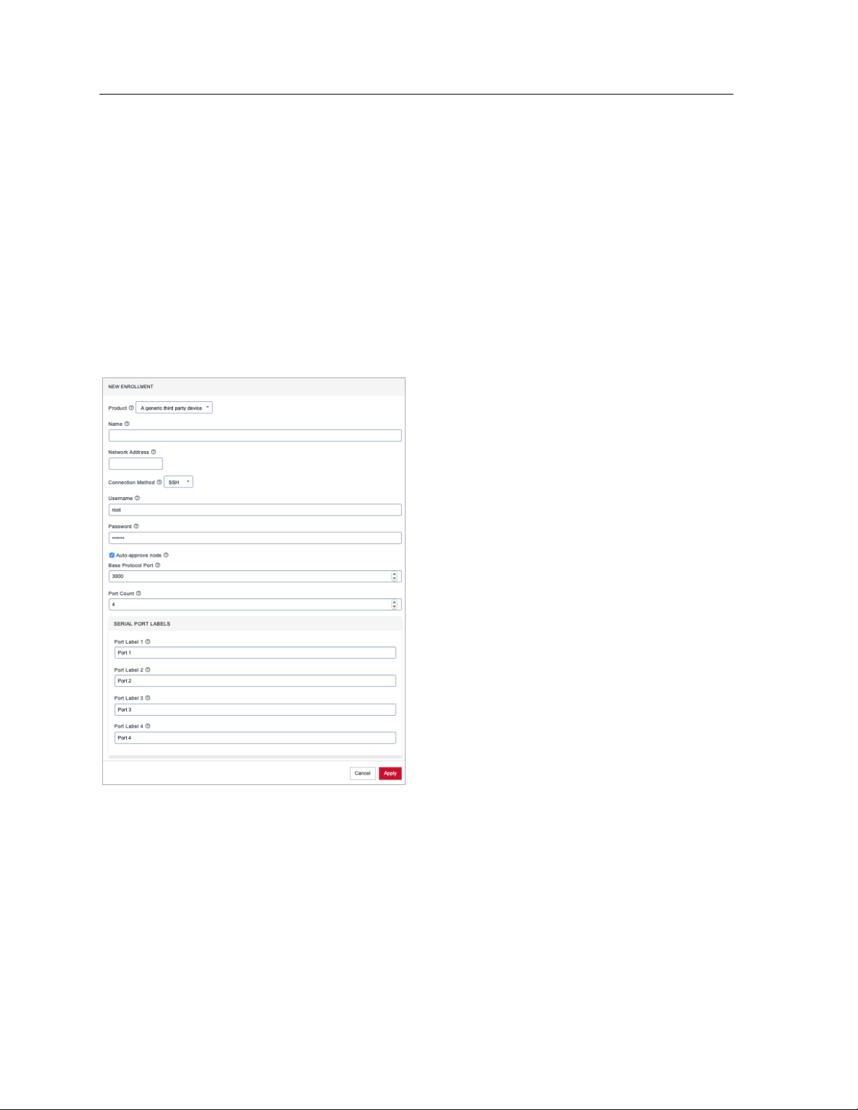
57
Lighthouse User Guide
4. Enter the Name, Network Address, Username, and Password of the node being enrolled. The
Username and Password fields are for the login credentials required by the remote node being
enrolled, not the login credentials used to login to the Lighthouse instance.
NOTE: Lighthouse populates the node name field with the hostname of the enrolled node rather
than a user provided value. It is no longer possible for users to specify a custom name, except
when enrolling third party nodes. Console servers with firmware 4.1.1 and higher provide their
hostname in the node information, with pre-4.1 nodes instead just having their node id used as
the name. Nodes enrolled prior to upgrading to 5 have their names switched to the new standard
if the node is running 4.1.1 firmware but retain their old name if older firmware is still installed.
5. To enroll a generic third-party device, there are three more required fields: Connection Method,
Base Protocol Port, and Port Count.
6. Choose SSH or Telnet from the Connection Method drop-down menu, as appropriate for the
connection method supported by the third-party device.
7. Enter a base number in the Base Protocol Port. By default, this is set to 3000. The Base Protocol
Port number is the starting port number from which the third-party device’s individual serial port
network port numbers will be derived.
8. Enter the number of serial ports the third-party device has in the Port Count field. Below the Port
Count field is a Serial Port Labels section. Whatever number is entered in the Port Count field, the
Port Label x fields in this section update to match.
9. Optionally, edit the labels used to identify each serial port in the Serial Port Labels section.
10. Click Apply.
Page 58

58
Lighthouse User Guide
Once enrolled, the console server’s details are removed from the Pending Nodes page and added to
the CONFIGURE > NODE ENROLLMENT > Enrolled Nodes page.
7.2.6 Enrollment via Node Web UI
If the node is situated behind a firewall, Lighthouse is not able to initiate an enrollment. It needs to be
triggered from the Node Web UI.
1. Log into the Node Web UI.
2. Select Serial & Network > LIGHTHOUSE.
3. Enter the Server Address of Lighthouse (which can be hostname, FQDN, or IP address)
4. Optionally, enter the Server Port.
5. Enter the Enrollment Bundle (if a specific bundle is being used), and the Enrollment Token
(either the global token or the bundle-specific token).
6. Select Apply Settings. The enrollment process begins.
7.2.7 Lighthouse Enrollment via OM, ACM, CM, and IM Web UI
• OM: Nodes can be enrolled into a Lighthouse instance on OPERATIONS MANAGER Web UI using
the CONFIGURE > LIGHTHOUSE Enrollment menu item and the lhvpn-callhome command.
See the OPERATIONS MANAGER User Guide for more details.
• ACM, CM and IM: On the Web UI, select Serial & Network > Lighthouse to open the Request
Enrollment with Lighthouse Server page.
7.2.8 Mass Enrollment using ZTP
For mass node enrollments using ZTP, three new custom DHCP fields are handled by ZTP scripts.
These fields contain the URL, Bundle Name and Enrollment Password used in an enrollment which is
kicked off after all other ZTP handling is completed. If a reboot is required because of a config file being
provided the enrollment starts after the reboot. Otherwise it happens immediately.
Here is a sample configuration file for the ISC DHCP Server:
option space opengear code width 1 length width 1;
Page 59

59
Lighthouse User Guide
option opengear.config-url code 1 = text;
option opengear.firmware-url code 2 = text;
option opengear.enroll-url code 3 = text;
option opengear.enroll-bundle code 4 = text;
option opengear.enroll-password code 5 = text;
class "opengear-config-over-dhcp-test" {
match if option vendor-class-identifier ~~ "^Opengear/";
vendor-option-space opengear;
option opengear.config-url "http://192.168.88.1/config.xml";
option opengear.enroll-url "192.168.88.20";
option opengear.enroll-bundle "";
option opengear.enroll-password "default";
}
NOTE: The maximum amount of data allowable as DHCP options is 1200 bytes, including all overhead
inherent in the structuring of this data. Individual options are limited to 255 characters.
7.2.9 Enrollment via USB drive
USB Enrollment enables the configuration of a device using a manifest file copied to a USB drive and
inserted into the unconfigured device before it first boots.
Once created (see Creating an enrollment bundle above), manifest.og files can be downloaded from a
Lighthouse instance as follows:
1. Select CONFIGURE > NODE ENROLLMENT > Enrollment Bundles. A list of existing Enrollment
Bundles appears.
2. In the Actions column of the particular bundle, click the download button, a downward arrow in a
circle.
3. Depending on the browser’s configuration, a manifest.og file is either downloaded to the local
system or the browser opens a dialog asking to specify where download should be copied.
To enroll via USB drive:
4. Copy manifest.og to the root directory on a USB drive.
5. Plug the USB drive into an unconfigured and powered-down console server.
6. Power the console server up.
On first boot, the device looks for a file — manifest.og — on any USB drives attached to the
device and configures the device based on their contents.
Page 60

60
Lighthouse User Guide
7.3 The Enrolled Nodes page
CONFIGURE > NODE ENROLLMENT > Enrolled Nodes lists all enrolled nodes in the order they are enrolled
to Lighthouse.
On the bottom right of the page is an Items per page drop-down that allows you to select the number of
nodes per page. Choose a default value of 10, 20, 50, 80, or 100 nodes per page, or enter a custom value
between 1 and 100. This setting applies to the current user session only and will be lost when current
user logs out. This drop-down is also presented on Pending Nodes, Console Gateway, and Node Web UI
pages.
It also displays details about each node (such as model, firmware version, serial number) and status.
Status is the current connection status of the node and displays either of two things:
• Connected: Last status change x [time unit] ago: The time since Lighthouse connected to the
console server.
• Disconnected: last status change x [time unit] ago: The time since Lighthouse disconnected from
the console server.
Configuration Retrieval Status displays if any configuration retrieval sections failed when performing a
configuration sync with this node, such as Groups, Users, Node Description, Authorization, or Serial Ports.
Configuration Template Run Status displays the result of the most recent configuration template push on
this node, listing which templates finished applying, or failed to apply to the node. This information is
displayed until the next template push has completed on this node.
The Configuration Retrieval Status and Configuration Template Run Status are not displayed if there is
no relevant data to display and are only displayed for users with Lighthouse Administrator or Node
Administrator permissions.
Results of the Configuration Retrieval Status and Configuration Template Run Status will indicate:
• Success: all templates were successfully executed on the node.
Page 61

61
Lighthouse User Guide
• Partial Failure: some templates failed to execute on the node, or some config sections failed to
synchronize.
• Failure: all templates failed to execute on the node, or all config sections failed to synchronize.
The detailed information is shown in a popover that appears when the summary of each status is
clicked on, navigated to, or hovered over. The format of the detailed information for each status
shown on relevant popovers is as follows:
• Retrieval failed for: section_name, section_name, section_name.
• Template(s) failed to apply: template_name, template_name, template_name.
• Template(s) successfully applied: template_name, template_name, template_name.
If SETTINGS > SERVICES > Cellular Health Reporting is Enabled, the Cellular Health column appears and
displays the node’s current cellular status. If this state is Good|Moderate|Bad, the color indicator and the
text are clickable links that open a popup containing detailed health information.
This popup includes the following information:
• Cellular IP Address (IPv4 and IPv6)
• Cellular interface status (Up|Down)
• Conditions
• Signal Quality
• RSSI
• Connection Type
• Sim Issues
• Connectivity Test (Passed|Failed|Connectivity Test Disabled)
7.4 Filtering pages displaying nodes
There are three ways to filter search results: Free Text Search, Smart Group Filtering, and Managed
Device Filtering. They can be used independently from each other or in combination. MANAGE >
MANAGED DEVICES > Console Gateway uses all of them because it is the only page which lists all nodes
with managed devices.
Page 62
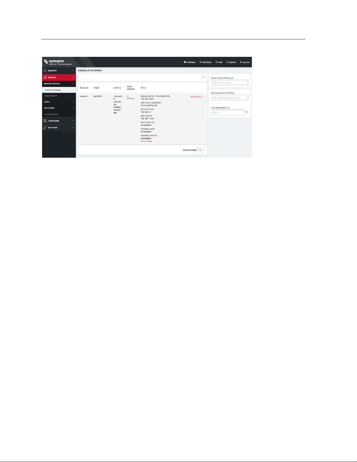
62
Lighthouse User Guide
7.4.1 Filtering using the Free Text Search field
The Free Text Search text-entry field allows the near real-time filtering. It searches over node name,
firmware version, management VPN address, MAC address, and serial number. Type a string (e.g. 4.1.1 or
192.168.128.1 or CM7148) and press Return. Only nodes which include that string in their Name or
Description are displayed.
The Free Text Search field treats multiple search terms (i.e. terms delimited by the space character) as
Boolean AND searches.
For example, a search on the string:
4.1.1 CM7148
returns any nodes that have both CM7148 AND 4.1.1 in searchable fields (e.g. CM7148 in the name field
and 4.1.1 in the firmware version field).
To make a search string that contains spaces into a single searched entity, enclose the string in double
quotes.
7.4.2 Filtering using the Smart Group Filtering drop-down menu
Selecting from the Select Smart Group drop-down menu sets the page to display the subset of nodes that
belong to the selected group. See Creating Smart Groups for how to create such groups.
Once a particular Smart Group has been selected, further filtering options become available under Fields
to search:
Page 63

63
Lighthouse User Guide
In the example above, the CONFIGURE > NODE ENROLLMENT > Enrolled Nodes page is being filtered on
the Sandy-4 Smart Group.
To add more filtering options:
1. Click Field to search.
2. Select a field and enter a value in the text box.
3. Select an Operator from the drop-down box on the right.
4. Click the + Add Parameters button. Select a parameter.
5. Click Apply.
7.4.3 Filtering using the Managed Device Filtering drop-down menu
Selecting from the Managed Device Filter drop-down menu sets the page to display the subset of nodes
that belong to the selected group. See Creating Smart Groups below for how to create such groups.
Once a particular Managed Device Filter has been selected, further filtering options become available
under Fields to search:
To add more filtering options:
1. Click Field to search.
2. Select a field and enter a value in the text box.
3. Select an Operator from the drop-down box on the right.
4. Click the + Add Parameters button. Select a parameter.
Page 64

64
Lighthouse User Guide
5. Click Apply.
7.5 Creating Smart Groups
Smart Groups are saved search parameters used within Lighthouse for grouping related remote nodes.
A user group can be linked to a particular Smart Group. When a group is linked in this fashion, members
of the group inherit rights over all nodes in the group based on the group’s role. See 8.3 Modifying existing
groups for how to set a group’s role and linked Smart Group.
Smart Groups can also be used to filter visible nodes on pages that display enrolled nodes (such as
CONFIGURE > NODE ENROLLMENT > Enrolled Nodes) to make it easier to drill down to a particular
console.
Smart Groups are dynamic, so as more nodes are added to the system, the filters update.
To create a Smart Group:
1. Navigate to any page which displays the Smart Group search interface, for example CONFIGURE
> NODE ENROLLMENT > Enrolled Nodes or MANAGE > NODES > Node Web UI.
2. Click on the Select Smart Group drop-down and select New Smart Group...
3. Click the Field to search drop-down to select a node attribute to filter on.
These attributes include details about the device (Internal VPN Address, MAC Address, Name,
Product, SSH Port, Firmware Version, Model, Serial Number, Node ID, Connection Status, Cell Health),
and include any tags that have been configured in the system. For filtering access to devices, tags are
the most useful attributes to filter on. When a tag is selected, the Field to search text box contains tag
values.
4. Click the Operator drop-down to select the operator to apply to the Value.
5. Select the Value to be matched against.
6. Click Apply to see the results of the filter.
7. Click Save As and type in a name for your new Smart Group.
This Smart Group can now be used for filtering nodes for display and for access.
Page 65
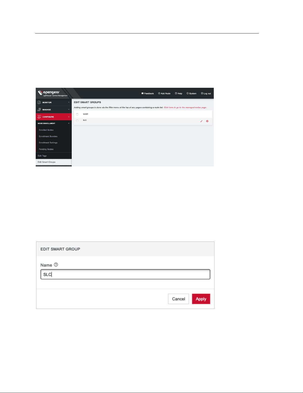
65
Lighthouse User Guide
7.6 Editing an existing Smart Group
To edit an existing Smart Group:
Select CONFIGURE > Edit Smart Groups.
• Click the Delete button to delete an existing Smart Group.
• Click the Edit Group button to change a Smart Group’s name.
To change the search parameters used by a Smart Group:
1. Navigate to a page that displays Smart Groups for filtering (e.g. CONFIGURE > NODE
ENROLLMENT > Enrolled Nodes).
2. Select the required Smart Group to be changed from the Select Smart Group drop-down menu.
3. Change the Tag and Operator values as required.
4. Click Save as.
5. Leave the Smart Group name unedited and click Apply. The changed Smart Group overwrites the
existing Smart Group.
Page 66
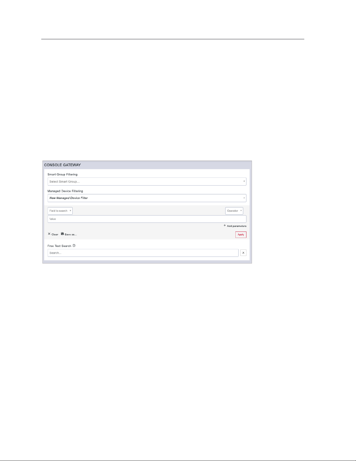
66
Lighthouse User Guide
7.7 Creating Managed Device Filters
Managed Device Filters are saved search parameters for grouping related managed devices on remote
nodes. Managed Device Filters can be used to filter visible nodes with managed devices on the MANAGE
> MANAGED DEVICES > Console Gateway page to make it easier to find a particular console.
Managed Device Filters are dynamic, so as more nodes with managed devices which match saved filters
are added to the system, the filters update.
To create a Managed Device Filter:
1. Navigate to the MANAGE > MANAGED DEVICES > Console Gateway page.
2. Click on the Select Managed Device Filter drop-down and select New Managed Device Filter.
3. Click the Field to search drop-down to select a node attribute to filter on.
4. Select Port Label configuration.
5. Click the Operator drop-down to select the operator to apply to the Value.
6. Populate the Value to be matched against.
7. Click Apply to see the results of the filter.
8. Click Save As and type in a name for the filter.
This Managed Device Filter can now be used for filtering nodes with managed devices.
7.8 Editing an existing Managed Device Filter
To edit an existing Managed Device Filter, select CONFIGURE > Edit Managed Device Filters page.
Page 67
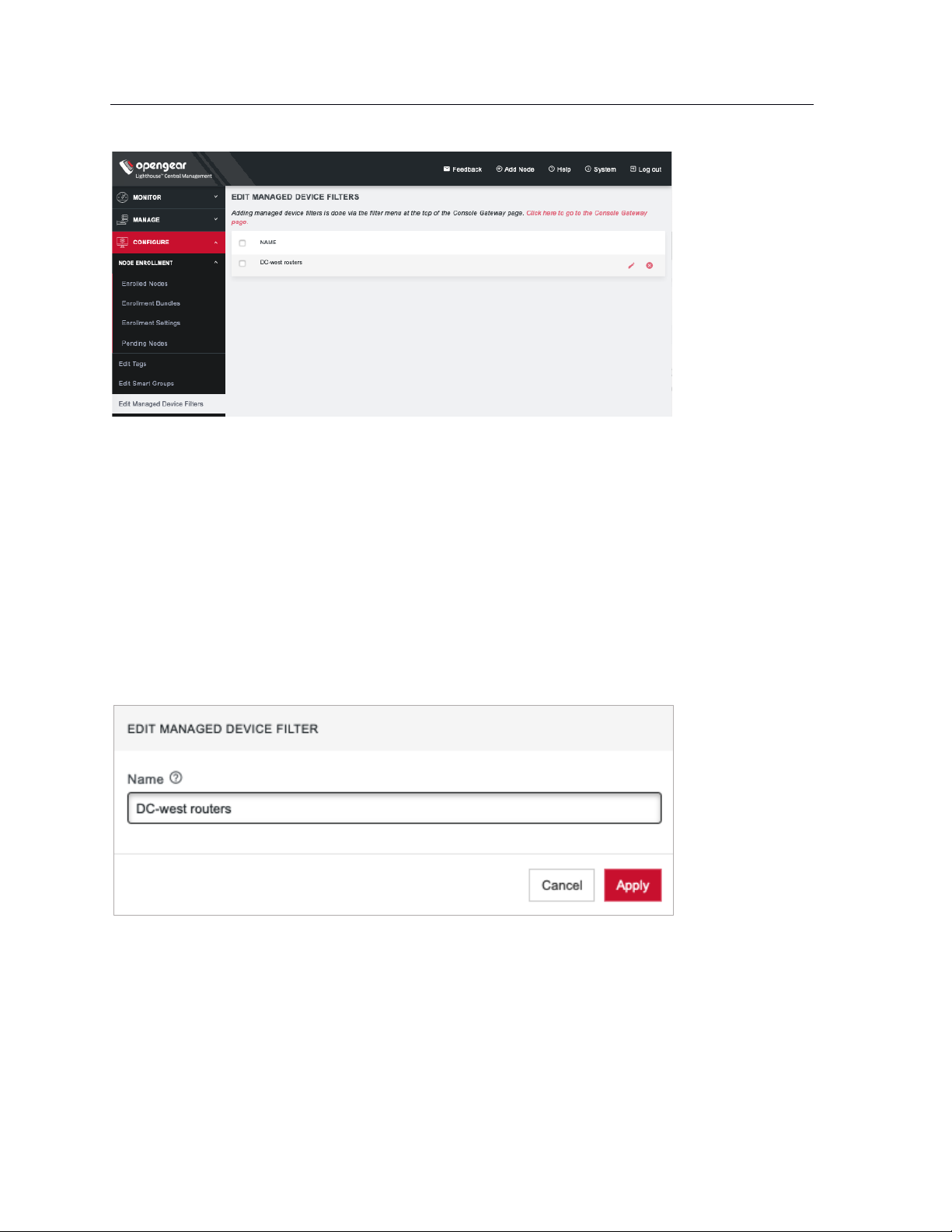
67
Lighthouse User Guide
• Click the Delete button to delete an existing Managed Device Filter.
• Click the Edit button to change a Managed Device Filter’s name.
To change the search parameters used by a Managed Device Filter:
1. Navigate to a page that displays Managed Device Filter, such as MANAGE > MANAGED DEVICES
> Console Gateway.
2. Select the Managed Device Filter to change from the Select Managed Device Filter drop-down
menu.
3. Change the parameters (e.g. Operator values) as required.
4. Click Save as.
5. Leave the Managed Device Filter name unedited and click Apply. The modified Managed Device
Filter overwrites the existing Managed Device Filter.
7.9 Connecting to a node’s web-management interface
Once a node has been enrolled, its own web-management interface can be accessed from within the
Lighthouse UI. To connect to an enrolled node’s web-management interface:
1. Select MANAGE > NODES > Node Web UI.
Page 68
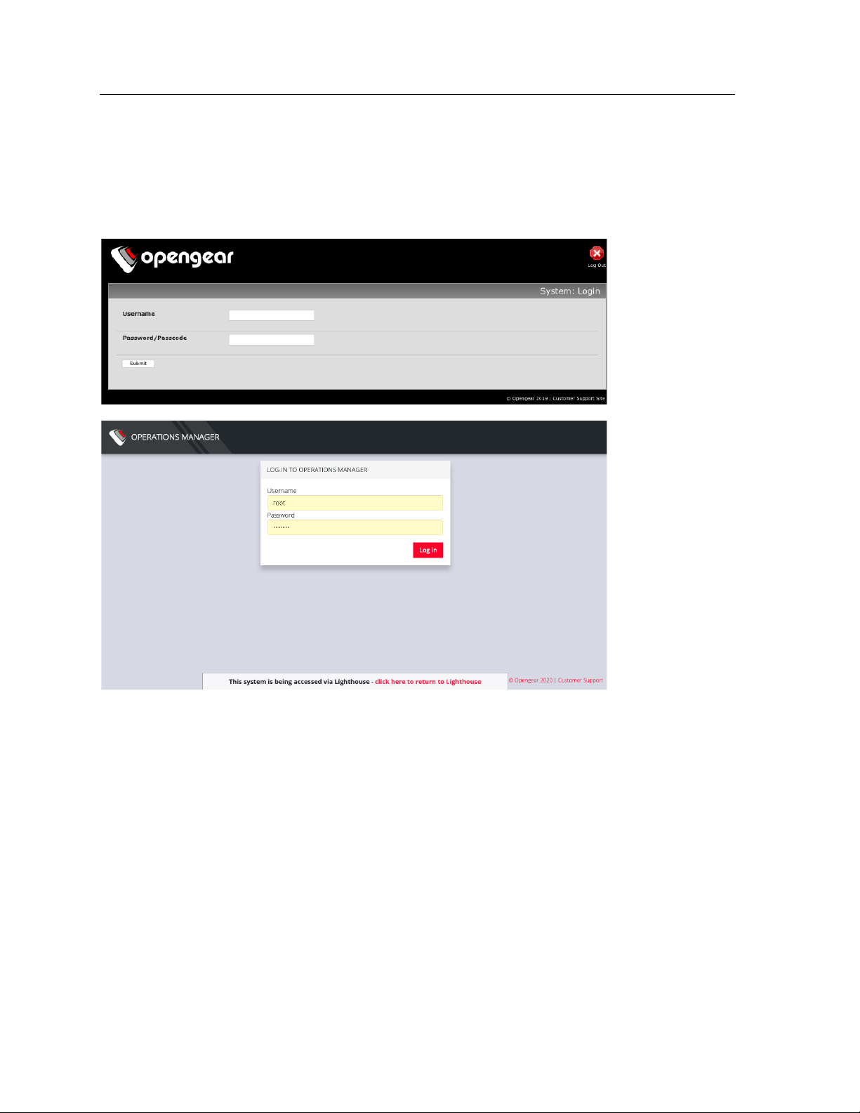
68
Lighthouse User Guide
2. In the Actions column, click the Access Web UI link for the particular node.
The web-based login for that node loads.
3. Authenticate using the username and password required by that node. The appearance of the
Web UI depends on which device you have added. Below is the ACM/CM/IM Web UI, followed by
the OM Web UI.
At the bottom of the browser window is a visual indication that the console server session is being
mediated through Lighthouse and a link allowing for a quick return to Lighthouse.
7.10 Connecting to a node’s serial ports via Console Gateway
Searching for serial ports on Lighthouse can be accomplished by selecting MANAGE > MANAGED
DEVICES > Console Gateway and MANAGE > MANAGED DEVICES > Quick Search.
The Items per page drop-down on Quick Search page allows user to select the number of ports per page.
Choose a default value of 10, 20, 50, 80, or 100 ports per page, or enter a custom value between 1 and
100. This setting applies to the current user session only and will be lost when user logs out.
NOTE: Port-centric search allows filtering via the Managed Device Filters and displays a list of ports
within enrolled nodes that match the search terms, while node-centric search allows filtering via Smart
Groups and node properties. Quick Search can be used to filter on the managed device label.
Page 69

69
Lighthouse User Guide
Node-centric searching
1. Select MANAGE > MANAGED DEVICES > Console Gateway.
2. Find the particular port using the Smart Group Filtering options to restrict the listed nodes.
3. Click the + button in the Access Console Ports row adjacent the particular node.
Port-centric searching
1. Select MANAGE > MANAGED DEVICES > Console Gateway.
2. Find the particular port by using the Managed Device Filtering options to restrict the listed
managed devices within enrolled nodes.
Once the serial port is located, serial port access via Console Gateway can be accomplished in two ways:
• HTML5 Web Terminal
• SSH
Quick Search
1. Select MANAGE > MANAGED DEVICES > Quick Search.
2. Enter the managed device label, aka name, in the Quick Managed Device Search field. This search
live-updates as user type.
3. Use Web Terminal and/or SSH links inside Actions on a particular port to access it.
7.10.1 Access via HTML5 Web Terminal
To provide easy console port access, Lighthouse includes a HTML5 Web Terminal. The HTML5 Web
Terminal includes native cut, copy and paste support. The terminals available on nodes do not.
To access a console port via the Web Terminal:
1. Locate the particular port by using one of the search techniques discussed above.
2. Click the Web Terminal link for the particular port. A new tab opens containing the Web Terminal.
To close a terminal session, close the tab, or type ~. in the Web Terminal window.
7.10.2 Access via SSH
To access ports via SSH, the user can either use a console chooser menu to select the node and the
console port or use a direct SSH link from the Web UI to connect to the port.
To access a console port via a Direct SSH link:
1. Locate the particular port by using one of the search techniques discussed above.
2. Click the SSH link to connect to the URL.
These auto-generated links use the colon (:) as the field-delimiter. The auto-generated SSH link has the
following form:
Page 70
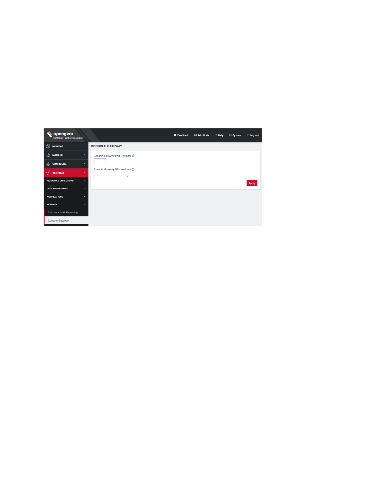
70
Lighthouse User Guide
ssh://user-name:console-server-name:port-number@lighthouse-ip-address
Some web browsers associate the colon character with delimiting the protocol at the beginning of a URI
so they don’t pass these auto-generated URIs correctly.
To work around this, the default delimiter character can be changed. To change this character:
Select SETTINGS > SERVICES > Console Gateway.
• Enter a delimited character in the Console Gateway Port Delimiter text-entry field. The carat, ^, is
the most common alternative.
• Use the Console Gateway SSH Address drop-down menu to choose an address from which to
SSH. The list of available addresses contains the current network interfaces and external network
addresses. The value defaults to net1:dhcp if it exists and net1:static otherwise. The additional
external addresses can be added to this list using the SETTINGS > SYSTEM> Administration
page.
To use the console chooser menu, SSH to the Lighthouse appliance with the username format
username:serial. This connects to the Lighthouse and presents a list of nodes that the user can access.
Once the user selects a node, they are presented with a list of console ports they have access to. When
one is selected, the user is connected to that port. For faster access, there are username format
shortcuts that give more specific lists of serial ports, or direct access without a menu.
• username:node_name
When a valid node name is specified, a list of console ports that the user can access on that node
is shown. If they do not have access to this node, the connection fails.
• username:node_name:port_name
When a valid node name and port name are specified, and the user has access to that node and
port, the user is connected to this port. If they do not have access to that port, the connection
fails.
• username:port_name
When a valid port name is specified, the user is connected to first port with that port name found.
If the user does not have access to this port, the connection fails.
NOTE: Node names and port names are not case sensitive.
Page 71

71
Lighthouse User Guide
7.10.3 Example Console Gateway session
$ ssh adminuser:serial@lighthouse-name-or-ip-here
1: cm71xx
Connect to remote > 1
1: Cisco Console 2: Port 2
Connect to port > 1
router#
Page 72
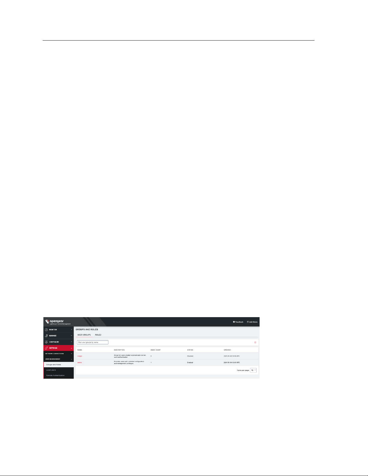
72
Role
Description
Lighthouse
Administrator
The Lighthouse Administrator role is assigned to groups whose members need to manage and
maintain the Lighthouse appliance. Members have access to all data on the Lighthouse system
Node
Administrator
The Node Administrator role is assigned to groups that need to manage and maintain a set of Nodes.
Each group with the Node Administrator role must have an associated Smart Group which is evaluated
to define the set of nodes that the group members have access to.
Node User
The Node User role is assigned to groups that need to access a set of nodes. Each group with the Node
User role must have an associated Smart Group which is evaluated to define the set of nodes that the
group members have access to. Optionally, access to the managed devices can be limited by
associating the saved Managed Device Filter with the Node User role.
Lighthouse User Guide
8. Lighthouse user management
Lighthouse supports locally defined users, and remote users that are authenticated and authorized by
AAA.
Users must be members of one or more groups. Each group has a role assigned to it which controls the
level of access that group members have to the system. These roles are:
Group membership can either be defined locally for local users or defined on the AAA server. Groups that
are assigned by the AAA servers must still exist locally.
8.1 Password fields in Lighthouse
All password fields in Lighthouse are write-only. They accept data from the clipboard or pasteboard but
do not pass data out.
8.2 Creating new groups and roles
8.2.1 CREATE A NEW GROUP
1. Select SETTINGS > USER MANAGEMENT > Groups and Roles. The User Groups tab should be
selected.
2. Click + on the upper right. The New Group page opens.
Page 73
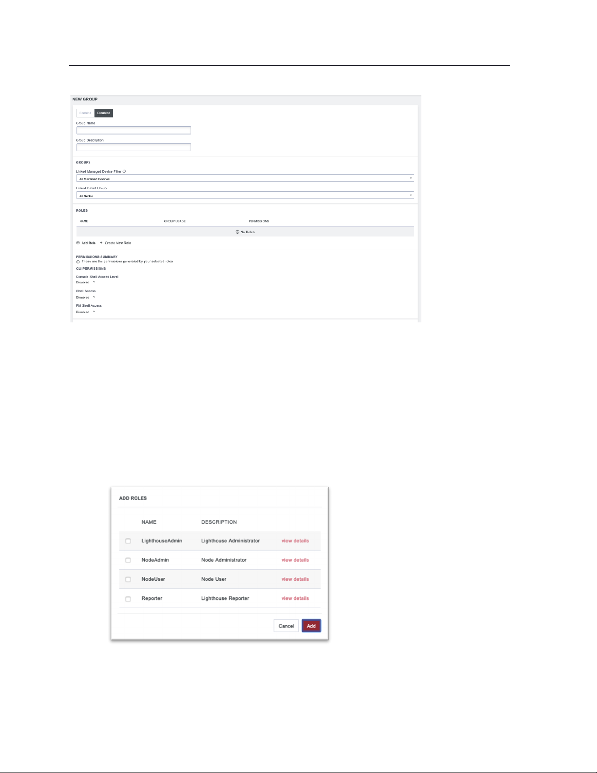
73
Lighthouse User Guide
3. Enter a Group Name and Group Description.
Group Name is case sensitive. It can contain numbers and some alphanumeric characters. When
using remote authentication, characters from a user's remote groups that are not allowed on
Lighthouse are converted to underscores during authentication. Local groups can be created that
take that into account, allowing the authentication to continue.
4. The CLI Permissions section displays permissions based on the roles you have assigned to this
group. To change the permissions, you can edit or add new roles with the desired CLI
Permissions. See CREATE A NEW ROLL below.
5. Click Enabled to enable group.
6. If desired, you can select a Linked Managed Device Filter and Linked Smart Group to associate
with this group.
7. Add one or more roles by clicking Add Role and checking the desired roles.
Each role has specific operation permissions associated with it and CLI (Command Line
Interface) access levels for console shell, shell, and PM shell. Click view details to see the
information for each group.
Page 74

74
Lighthouse User Guide
8. You can also control the new group’s permissions independently of the roles you add to your
group. Scroll to the bottom of the page to specify Full Access, Read Only, or Deny. Click to the
right of each Operation row to see all options.
NOTE: See Available Operations Permissions below for a list of all options.
9. Click Save Group.
Page 75
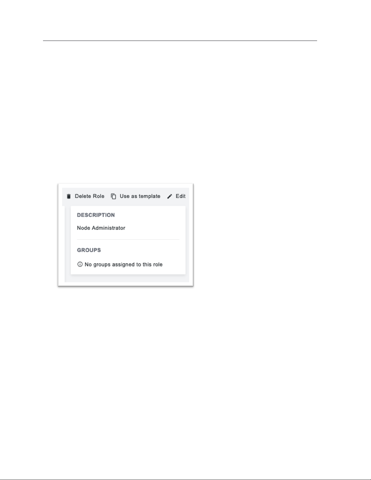
75
Lighthouse User Guide
Available Roles:
Lighthouse Administrator: Members of groups with this role have Full access to all nodes and
managed devices.
NodeAdmin: Has no shell access. Has Read Only access to Netops Modules, all Nodes &
Congfiguration Operations, Cell Health, Smart Groups, Tags, and Jobs.
NodeUser: Has PM Shell access. Has Read Only access to Nodes & Devices (Base) and Tags.
Lighthouse Reporter: Has no shell access. Has Read Only access to all Operations.
You can also create a custom role that allows you to modify CLI Permissions and Operations
Permissions by clicking Create New Role on the New Group page.
A new role can also be based on an existing role with the Use as template link on the upper right of a
role’s detail page.
Available Operations Permissions:
Actions
Events – Enable or disable if events are used to generate notifications.
Subscriptions – Manage third-party access to events.
Logging
Port Logging – Manage port logging settings.
Syslog – Manage system syslog settings.
Netops
Netops Modules
Nodes & Configuration
Nodes & Devices (Base) – Access to dashboard, nodes, managed devices, node enrollment,
console gateway, and Node web UI.
Nodes & Devices (Advanced) – Access to jobs, pending nodes, smart groups, and managed
device filters.
Template Push – Manage templates and push templated to nodes.
Service Settings
LHVPN
Cell Health
Page 76

76
Lighthouse User Guide
Console Gateway
Date & Time
HTTPS
Netops – Install Netops modules and manage local Netops repositories.
Node Backup
Session Settings
SNMP
SSH
Syslog
Smartgroups & Tags
Bundles – Manage and use bundles.
Smart Groups – Manage and use smart groups.
Tags – Manage and use tags.
System
Admin & Licensing – Manage access settings for Lighthouse and license settings.
Backup & Restore
Jobs
Multi-instance – Manage multi-instance settings and control state of instances.
Network Interfaces – Manage network interface settings.
System Upgrade & Reset
Users & Permissions
Authentication – Manage authentication settings including methods, policies, and restrictions.
Groups & Roles – Create and edit groups and roles. May not assign them to users.
Users – View, manage, create, and delete users.
Page 77

77
Lighthouse User Guide
NOTE: When a new group is given the Lighthouse Administrator role, members of the group have access
to the sudo command. Groups or users with the Lighthouse Administrator role are added to the admin
group, which is in the list of allowed sudoers. On first boot of a new Lighthouse instance, the root user is
the only member of the admin group and the only user with sudo access.
8.2.2 CREATE A NEW ROLE
1. Select SETTINGS > USER MANAGEMENT > Groups and Roles.
2. Click the ROLES tab.
3. Click + on the upper right. The Create Role page opens.
4. Enter a Role Name and Role Description.
5. Modify the CLI Permissions for as desired.
Console Shell Access: Ability to connect to nodes’ command lines via Lighthouse’s SSH.
Shell Access: Ability to access Lighthouse’s command line as administrator.
PM Shell Access: Ability to connect to serial ports via SSH.
Page 78

78
Lighthouse User Guide
6. You can also control the new roles Operation Permissions independently. Specify Full Access,
Read Only, or Deny. Click to the right of each Operation row to see all options.
NOTE: See Available Operations Permissions for a list of all options.
7. Click Save Role.
A new role can also be based on an existing role with the Use as template link on the upper right of a
role’s detail page.
8.3 Modifying existing groups
To modify an existing group:
1. Select SETTINGS > Groups and Roles. If necessary, click on the USER GROUPS tab.
2. Click the name of the group to be modified.
3. Click the Edit icon on the upper right and make desired changes.
4. Click Save Group.
Page 79

79
Lighthouse User Guide
The group details page allows the group’s Description, Role, Linked Smart Group, and Linked Managed
Device Filter to be set and changed.
If a Group’s Role is Lighthouse Administrator, the group’s Linked Smart Group is All Nodes and Linked
Managed Device Filter is All Managed Devices. This cannot be changed. If a Group has a Linked Smart
Group other than All Nodes or a Linked Managed Device Filter other than All Managed Devices, the group’s
Role cannot be set to Lighthouse Administrator.
See 7.5 Creating Smart Groups for details regarding creating and using Smart Groups and Creating
Managed Device Filters for details regarding creating and using Managed Device Filters.
The Groups page also allows you to delete groups. All users who were members of the deleted group lose
any access and administrative rights inherited from the group.
NOTE: The netgrp group is inherited as the primary group for all remote AAA users who are not defined
locally on Lighthouse. By default, netgrp has the Lighthouse Administrator role and is disabled - it must
be enabled to take effect for remote AAA users.
8.4 Use an existing group as a template for a new group
To use an existing group as a template for a new group:
1. Select SETTINGS > USER MANAGEMENT > Groups and Roles. If necessary, click on the USER
GROUPS tab.
2. Click the name of the group to be used as a template.
3. Click the Use as Template icon on the upper right. This opens a new group page with the settings
from the group you selected as a template.
4. Change the Group Name and make and other desired changes.
5. Click Save Group.
Page 80
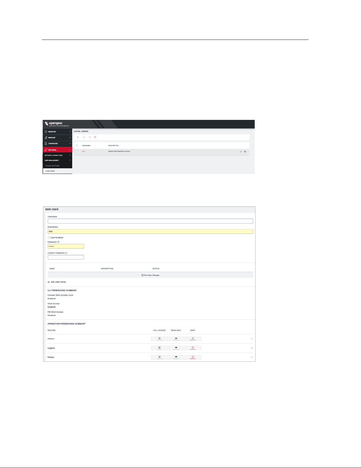
80
Lighthouse User Guide
8.5 Creating new local users
To create a new local user:
1. Select SETTINGS > USER MANAGEMENT > Local Users.
By default, the root user is the only user listed.
2. Click the + button. The New User page appears.
3. Enter a Username, Description, and Password.
4. Re-enter the Password in the Confirm Password field.
5. Click on Add User Group to add this user to any existing User Groups.
6. Choose which CLI options this user should have.
7. Select any Operation Permissions this user should have.
8. Select the User Enabled checkbox.
9. Click Save User.
Page 81

81
Lighthouse User Guide
To create a new user without password which causes them to fail back to remote authentication:
1. Select SETTINGS > USER MANAGEMENT > Remote Authentication
2. Choose a Scheme and enter appropriate settings.
3. Select SETTINGS > USER MANAGEMENT > Local Users
4. Click the + button. The New User dialog loads.
5. Enter a Username and Description.
6. Select the Remote Password Only checkbox.
7. Select the Enabled checkbox.
8. Click Apply.
NOTE: When a new user is created, an entry is added to the syslog, indicating the new user's name, the
user that performed the operation, database queries, and the time that it occurred:
2020-05-22T16:22:46.490627+01:00 localhost rest_api_log[62]: GET 200 (root |
192.168.1.230) - /api/v3.5/users?page=1&per_page=10 RESPONSE={'users': [{'username':
'root', 'description': 'System wide SuperUser account', 'enabled': True, 'id': 'users1', 'no_password': False, 'expired': False, 'locked_out': False, 'rights': {'delete':
True, 'modify': True}, 'groups': ['groups-2']}, {'username': 'fred', 'description':
'fred', 'enabled': True, 'id': 'users-2', 'no_password': False, 'expired': False,
'locked_out': False, 'rights': {'delete': True, 'modify': True}, 'groups': ['groups2']}], 'meta': {'total_pages': 1}}
If the created user is set to disabled, the configurator_users message does not appear as they have
not been added to the passwords file.
The syslog can be accessed from Lighthouse by clicking Help > Technical Support Report.
8.6 Modifying existing users
To edit settings for an existing user:
1. Select SETTINGS > USER MANAGEMENT > Local Users
2. Click the name of the user to edit this user and make desired changes. You may change CLI
access and specific access to operations. You may also control which groups this user is a
member of.
3. Click Save User.
Page 82
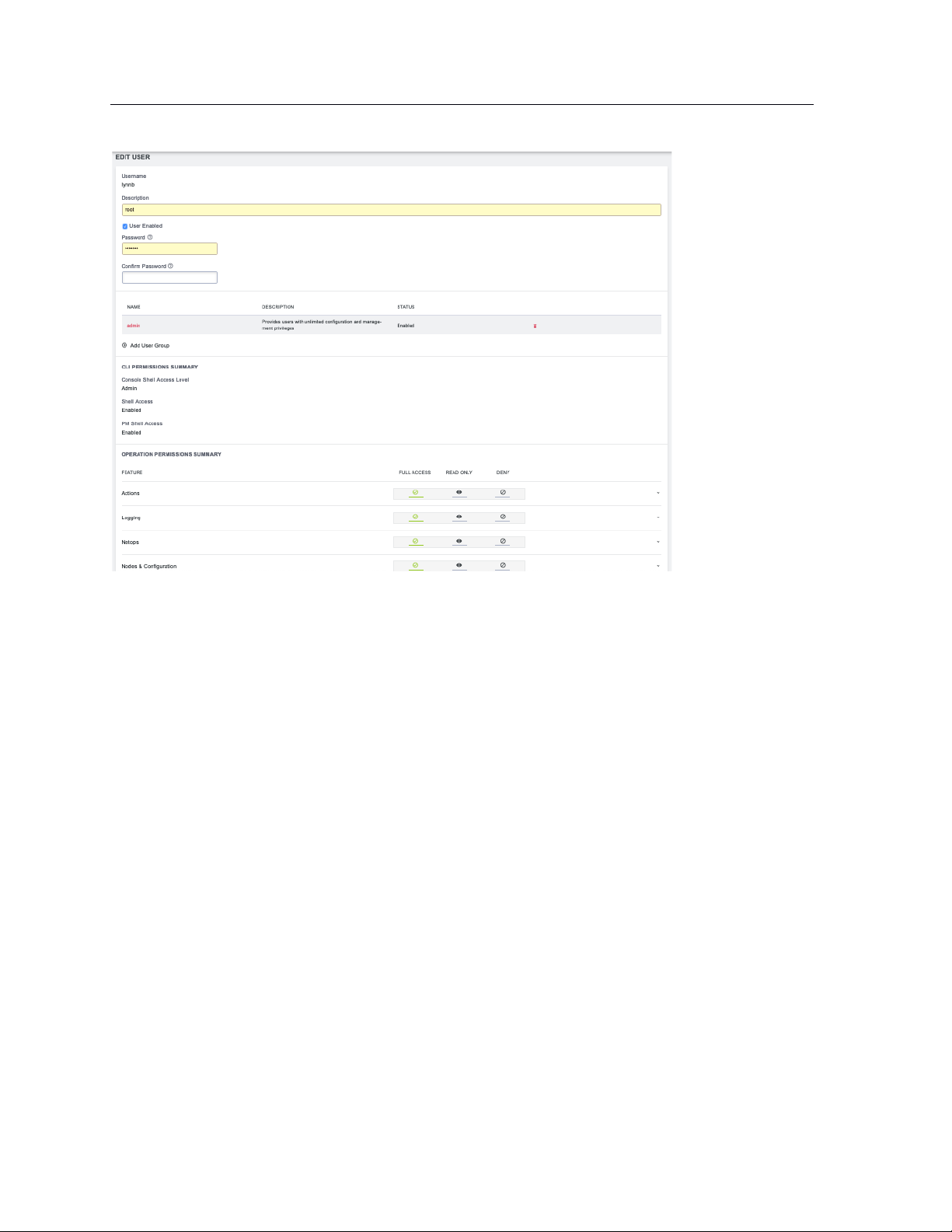
82
Lighthouse User Guide
The Edit Users dialog also allows the user’s Description to be changed and the user’s Password to be
reset. The username cannot be changed. To disable a user, uncheck the Enabled checkbox.
Disabled users cannot login to Lighthouse using either the Web-based interface or via shell-based logins
(i.e. sshusername-disabled@lighthouse-name-or-ip). The user and the /home/username-disabled directory
still exist in the Lighthouse VM file system.
8.7 Expire user password
You can set user passwords to expire. To expire a user’s password:
1. Select SETTINGS > USER MANAGEMENT > Local Users
2. Click the Expire Password button in the Actions section of the user to be deleted.
3. Click Yes in the Confirmation dialog.
The next time this user logs in, the user will be required to change the password.
Page 83
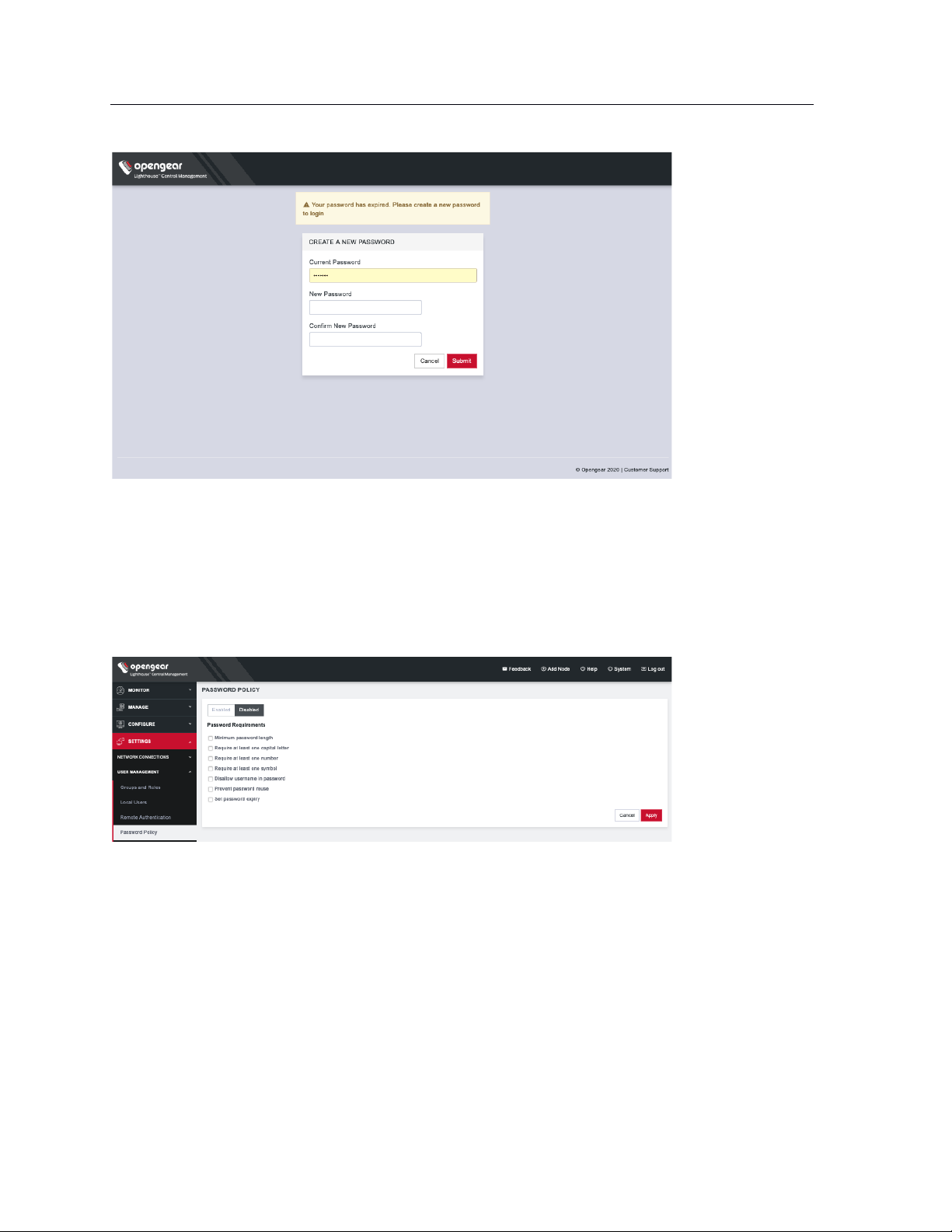
83
Lighthouse User Guide
8.8 Setting password policy
Lighthouse Administrators can apply Password Policies. To do so, select SETTINGS > USER
MANAGEMENT > Login Restrictions, choose Enabled, and click Save. Click Password Policy.
Choose one or more options from the following:
• Minimum password length – from 1 to 128
• Require at least one capital letter
• Require at least one number
• Require at least one symbol
• Disallow username in password
• Prevent password reuse – choose a number of days or select Always
• Set password expiry – select a number of days until passwords expire. At next login, the user will
need to reset the password.
Page 84

84
Lighthouse User Guide
8.9 Deleting users
To delete a user:
1. Select SETTINGS > USER MANAGEMENT > Local Users
2. Click the Delete button in the Actions section of the user to be deleted.
3. Click Yes in the Confirmation dialog.
8.10 Disabling a Lighthouse root user
To disable a root user:
1. Make sure that another user exists that is in a group that has the Lighthouse Administrator role.
2. Select SETTINGS > USER MANAGEMENT > Local Users
3. Click Disable in the Actions section of the root user.
4. Click Yes in the Confirmation dialog.
To enable root user back log in with another user exists that is in a group that has the Lighthouse
Administrator role and click Enable in the Actions section of the root user.
8.11 Configuring AAA
Lighthouse supports three AAA systems:
• LDAP (Active Directory and OpenLDAP)
• RADIUS
• TACACS+
Authentication works much the same with each, but group membership retrieval varies. The following
sections detail the configuration settings for each provider and explain how group membership retrieval
works.
To begin, select SETTINGS > USER MANAGEMENT > Remote Authentication.
Page 85
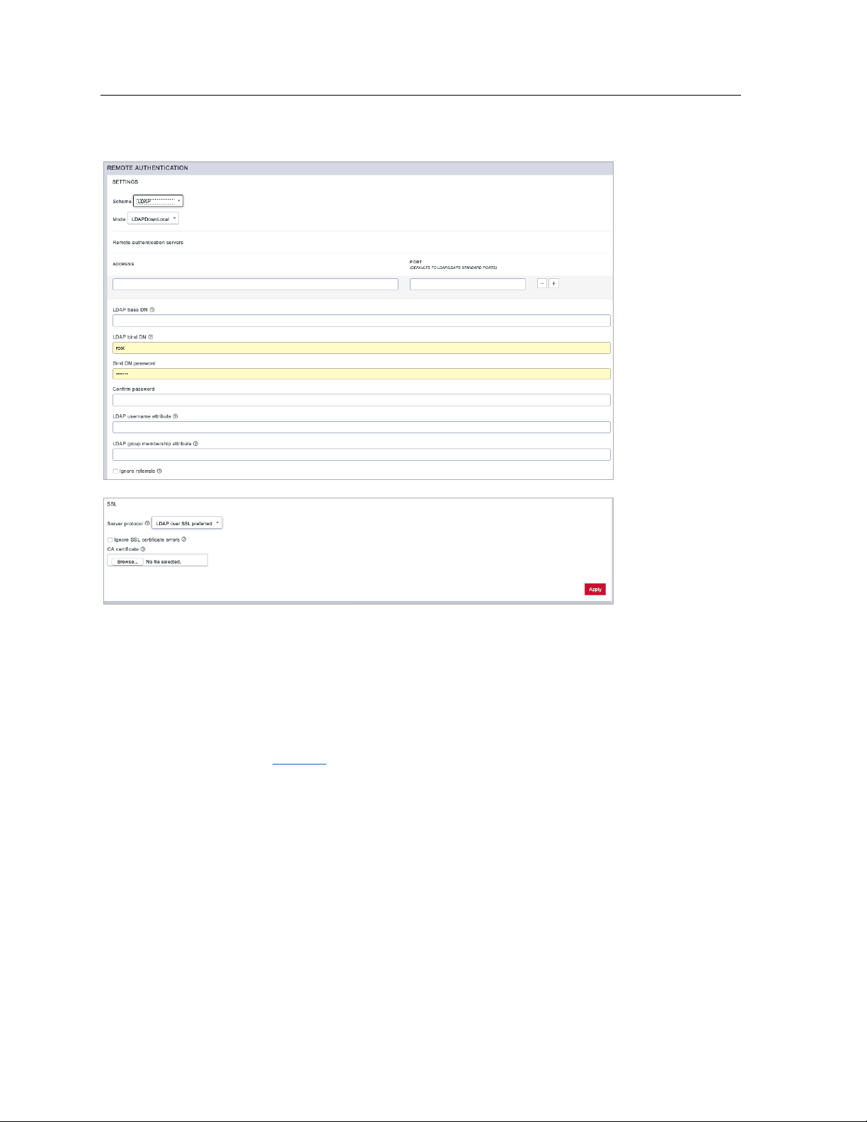
85
Lighthouse User Guide
8.11.1 LDAP Configuration
1. Select LDAP from the Scheme drop-down menu.
2. Choose the desired Mode from the drop-down menu.
• LDAPDownLocal
• LDAP: Default behavior
• LDAP/Local
• Local/LDAP
NOTE: See the Glossary for more information about these modes.
3. Add the Address and optionally the Port of the LDAP server to query.
4. Add the LDAP Base DN that corresponds to the LDAP system being queried.
For example, if a user’s distinguished name is cn=John Doe,dc=Users,dc=ACME,dc=com, the
LDAP Base DN is dc=ACME,dc=com
5. Add the LDAP Bind DN. This is the distinguished name of a user with privileges on the LDAP
system to perform the lookups required for retrieving the username of the users, and a list of the
groups they are members of.
6. Add and confirm a password for the binding user.
7. Add the LDAP username attribute. This depends on the underlying LDAP system. Use
sAMAccountName for Active Directory systems, and uid for OpenLDAP based systems.
Page 86
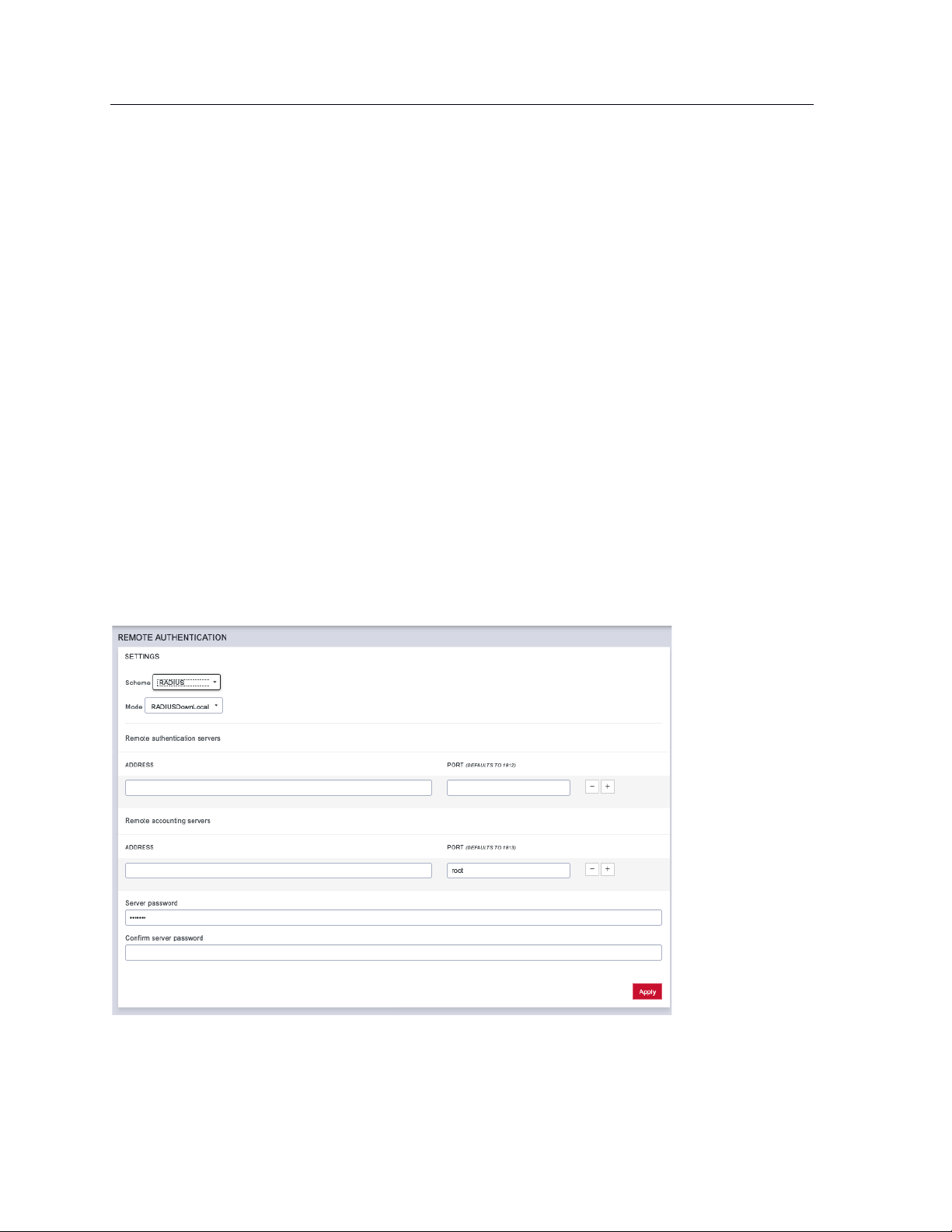
86
Lighthouse User Guide
8. Add the LDAP group membership attribute. This is only needed for Active Directory and is
generally memberOf.
9. If desired, check Ignore referrals option. When checked, LDAP will not follow referrals to other
remote authentication servers when logging users in to Lighthouse. If multiple remote
authentication servers exist on the network, checking this option may improve login times.
10. Under the SSL section, choose the desired Server protocol.
LDAP over SSL preferred: this will attempt LDAPS before trying LDAP without SSL
LDAP (no SSL) only: non-SSL LDAP is always used
LDAP over SSL only: LDAP over SSL is always used
11. If desired, check Ignore SSL certificate errors to ignore any SSL certificate errors.
12. CA Certificate is used to upload an SSL Certificate which will verify any LDAP servers you specify
on the page.
NOTE: The certificate will be uploaded but will not be used if you've chosen to ignore certificate
errors.
13. Install the CA certificate by clicking the Browse… button and locating the appropriate file.
14. Click Apply.
NOTE: Multiple servers can be added. The LDAP subsystem queries them in a round-robin fashion.
8.11.2 RADIUS configuration
To configure RADIUS:
1. Select SETTINGS > USER MANAGEMENT > Remote Authentication.
2. In the Settings section, select RADIUS from the Scheme drop-down menu.
3. Choose the desired Mode from the drop-down menu.
• RADIUSDownLocal
Page 87
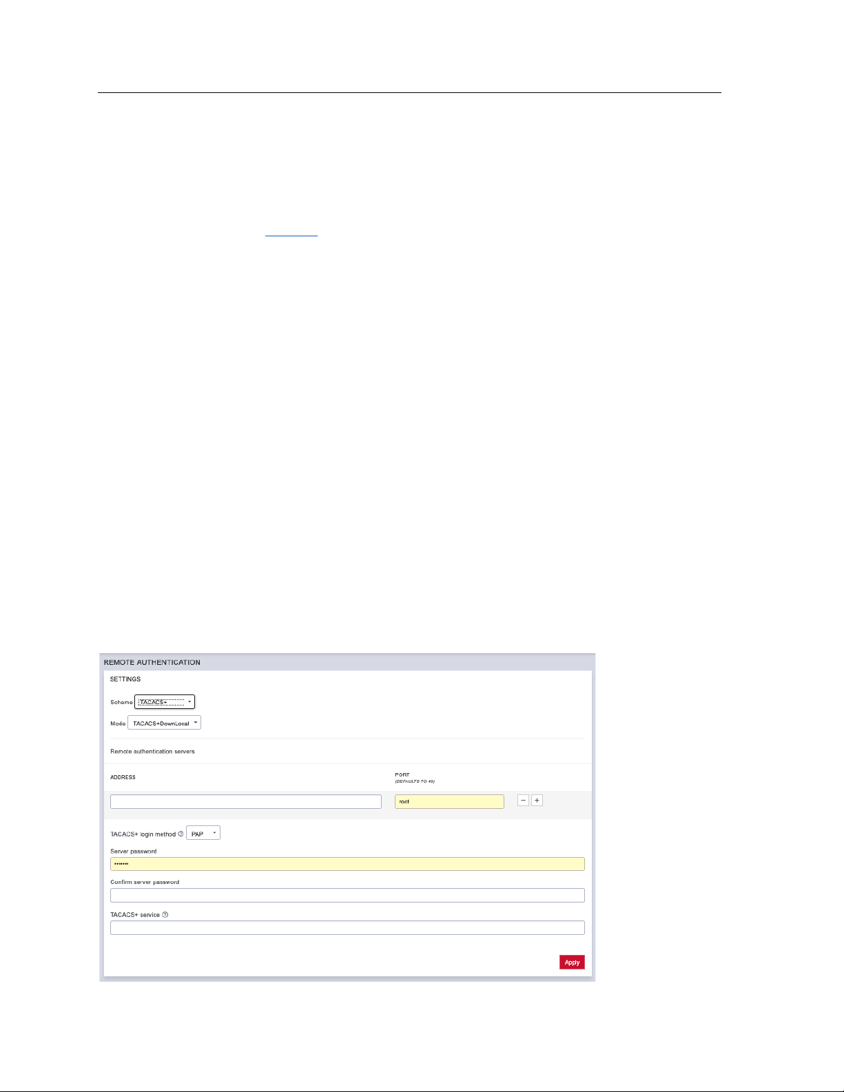
87
Lighthouse User Guide
• Radius
• RADIUS/Local
• Local/RADIUS
NOTE: See the Glossary for more information about these modes.
4. Add the Address and optionally the Port of the RADIUS authentication server to query.
5. Add the Address and optionally the Port of the RADIUS accounting server to send accounting
information to.
6. Add the Server password, also known as the RADIUS Secret.
NOTE: Multiple servers can be added. The RADIUS subsystem queries them in a round-robin fashion.
To provide group membership, RADIUS needs to be configured to provide a list of group names via the
Framed-Filter-Id attribute. The following configuration snippet shows how this can be configured for
FreeRADIUS:
operator1 Auth-Type := System
Framed-Filter-ID = ":group_name=west_coast_admin,east_coast_user:"
NOTE: The Framed-Filter-ID attribute must be delimited by the colon character.
8.11.3 TACACS+ configuration
To configure TACACS+:
1. Select SETTINGS > USER MANAGEMENT > Remote Authentication.
Page 88
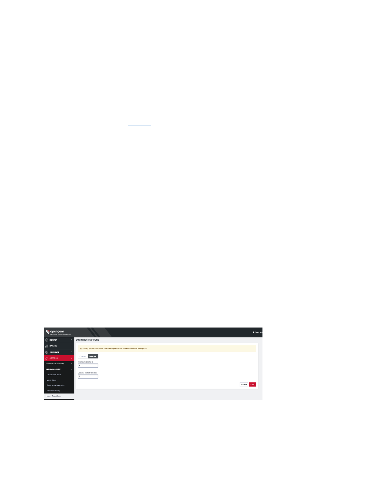
88
Lighthouse User Guide
2. Select TACACS+ from the Scheme drop-down menu.
3. Choose the desired Mode from the drop-down menu.
• TACACSDownLocal:
• TACACS: Default behavior
• TACACS/Local
• Local/TACACS
NOTE: See the Glossary for more information about these modes.
4. Add the Address and optionally the Port of the TACACS+ authentication server to query.
5. Select the Login Method. PAP is the default method. However, if the server uses DES-encrypted
passwords, select Login.
6. Add the Server password, also known as the TACACS+ Secret.
7. Add the Service. This determines the set of attributes sent back by the TACACS+ server
NOTE: Multiple servers can be added. The TACACS+ subsystem queries them in a round-robin fashion.
To provide group membership, TACACS+ needs to be configured to provide a list of group names This
following configuration snippet shows how this can be configured for a tac_plus server:
user = operator1 {
service = raccess {
groupname = west_coast_admin,east_cost_user
}
}
To do this with Cisco ACS, see Setting up permissions with Cisco ACS 5 and TACACS+ on the Opengear
Help Desk.
8.12 Setting login restrictions
Admin users can apply Login Restrictions. Select SETTINGS > USER MANAGEMENT > Login
Restrictions.
Enter a value for either or both of the following:
Page 89
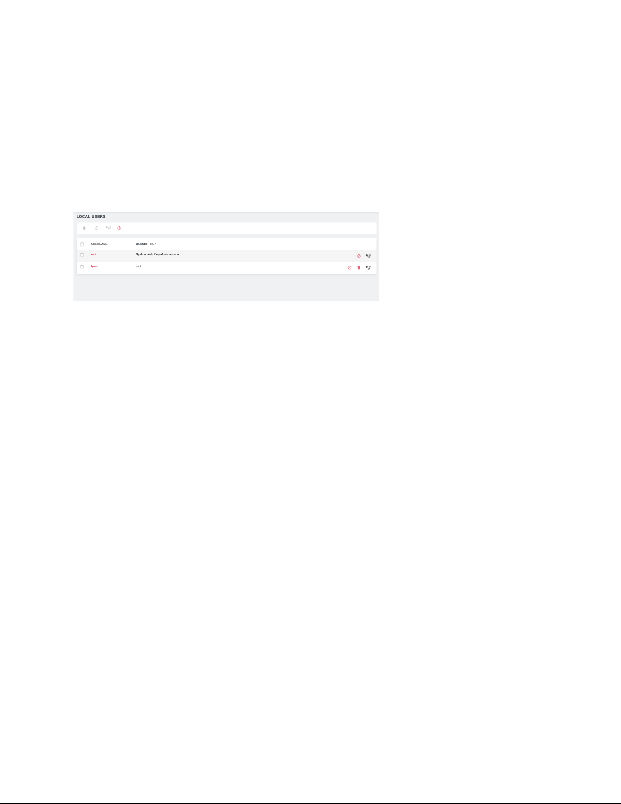
89
Lighthouse User Guide
• Maximum attempts – choose a number of attempts a user can enter an incorrect password
before being locked out.
• Lockout period – enter a number of minutes until a user can try to login again after reaching
maximum incorrect login attempts.
After a user has been locked out, an administrator can unlock the account. To do this, go to SETTINGS >
USER MANAGEMENT > Local Users. Click the Unlock button associated with the locked out user’s row in
the User table.
Page 90

90
Lighthouse User Guide
9. Notifications
Lighthouse has a MessageBus functionality that allows you to connect Lighthouse to third party systems
for notifications, ticket creation, and alerts.
Lighthouse allows integrations such as:
If a node goes into failover mode
• Create a trouble ticket with your companies Zendesk trouble ticketing system
• Trigger an alert to the companies on call scheduled via PagerDuty
If Lighthouse license is 45 days from expiry
• Send an email to purchasing
• Create a calendar notification
Zapier is the first integration that is available within Lighthouse. In order for events to be fired from
Lighthouse and received by Zapier:
• The Lighthouse should have a valid enterprise license.
• The event should be enabled on Lighthouse.
• There must be a Zap created to handle the event.
Once these requirements are met, a user will be able to receive Lighthouse event messages via third-party
apps integrated with Zapier.
To enable events, go to SETTINGS > NOTIFICATIONS > Events. Click the checkbox next to the desired
event to select it and click the Enable button at the top of the table to enable it. To enable all events, click
the checkbox on the top left of the screen and click the Enable button.
To disable an event, select the checkbox next to it, then the Disable button at the top of the screen.
Page 91
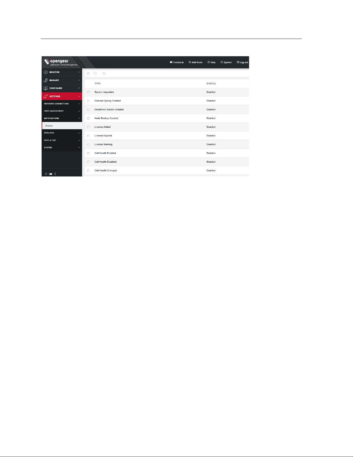
91
Lighthouse User Guide
Known Issues/Limitations/Warnings
• Secondary Lighthouses will not be able to send events to messagebus.
• Unknown behavior and errors can be expected in case the user tries to integrate a secondary
Lighthouse with Zapier and creates zaps.
• Modifying the system time will result in unexpected behavior with events being triggered.
• Zapier does not support IPv6.
Here are the specific events currently supported.
• System Upgraded: Event fired when Lighthouse is upgraded
• External Syslog Created: Event fired by Lighthouse when a user creates external syslog server.
• Enrolment Bundle Created: Event fired when a user creates a new enrolment bundle.
• Node Backup Created: Event fired when a node backup is created by the user. This event will only
fire if there are nodes enrolled and a backup is successfully created.
• License Added: Event fired when a user imports a new license.
• License Expired: Event fired when a license expires.
• License Warnings (60/45/30/15): Event fired warning user that their Lighthouse license will
expire in 60 → 45 → 30 → 15 days.
• Cell Health Enabled: Event fired when user enables cell health on Lighthouse.
• Cell Health Disabled: Event fired when user disables cell health on Lighthouse.
• Cell Health Changed: Event fired when a node’s cell health changes in the order Good > Moderate,
Moderate > Bad, Good > Bad and all in reverse.
• Node Enrolled: Event fired when a node enrolls into Lighthouse.
• Node Unenrolled: Event fired when a node unenrolls from Lighthouse.
• Node Failed Over: Event fired when a node fails over to the designated failover interface.
• Node Failed Back: Event fired when a node fails back to primary interface.
• Node Port Logging Enabled: Event fired when node port logging is enabled.
• Node Port Logging Disabled: Event fired when node port logging is disabled.
• User Created: Event fired when a user is created.
• User Deleted: Event fired when user is deleted.
Page 92

92
Lighthouse User Guide
• Group Created: Event fired when group is created.
• Group Deleted: Event fired when group is deleted.
• Role Created: Event fired when role is created.
• Role Deleted: Event fired when role is deleted.
Page 93

93
Lighthouse User Guide
10. Lighthouse central configuration
Templates are a centralized way of changing the configuration for enrolled Opengear console server
nodes by pushing pre-defined configuration templates to selected nodes. Lighthouse supports the
creation and execution of Users and Groups, Authentication and Script templates.
10.1 Creating new users and groups templates
Administrators can access CONFIGURE > CONFIGURATION TEMPLATING > Users and Groups
Templates to create, edit, and delete users and groups templates. Each template must contain at least
one group.
Each template contains a list of user-defined groups and/or individual users. Each group has a defined
role which determines what privileges group members have. User roles are defined by the groups they are
a member of.
The available group roles are:
• Node Administrator — maps to the administrator role on the nodes.
• Node User — maps to the ports user role and the pmshell role on the nodes. Ports access can be
restricted if required.
To create a new users and groups template:
1. Select CONFIGURE > CONFIGURATION TEMPLATING > Users and Groups Templates.
2. Click the + button. The New Users and Groups Template page loads.
Page 94

94
Lighthouse User Guide
3. Enter a Name and Description for a template in the Template Details section.
4. Click the + Add a group button in the Set Group List section to add a new group. The Group
Details dialog loads.
5. Enter a Group Name, a Description, and select a Role for the group.
6. If Node User role is selected, the Restrict accessible Serial Ports checkbox and Serial Ports
range appear.
7. Use the checkbox to restrict access and specify as port or range of ports in the Serial Ports range
text box.
8. Click Apply.
9. Click the + Add a user button in the Set User List section to add new users. The User Details
dialog loads.
10. Enter a Username, a Description, and a Password for the user. Type the password again in the
Confirm Password text box.
11. Optionally, click checkboxes next to the groups this user should belong to. Only groups from this
template are available.
12. Click Apply.
13. Continue adding new groups and users until finished.
14. Click Save Template.
NOTE: When a users and groups template is pushed to a node, all custom groups on that node are
replaced by groups defined in the template. If no users are in the new template, existing users will
Page 95

95
Lighthouse User Guide
remain on the node. To push users, the selected nodes need to be running firmware version 4.3.0 or
later.
10.2 Modifying existing users and groups templates
The Edit Users and Groups Template dialog allows a template’s Description, Group List, and User List to
be set and changed.
To modify a template:
1. Select CONFIGURE > CONFIGURATION TEMPLATING > Users and Groups Templates.
2. Click Edit button next to the template to be modified. The Edit Users and Groups Template dialog
appears.
3. Make changes to the template’s details, group list, or Individual user list as required.
4. Click the x button under Actions next to any groups or users which need to be removed.
5. Click Save Template.
Page 96
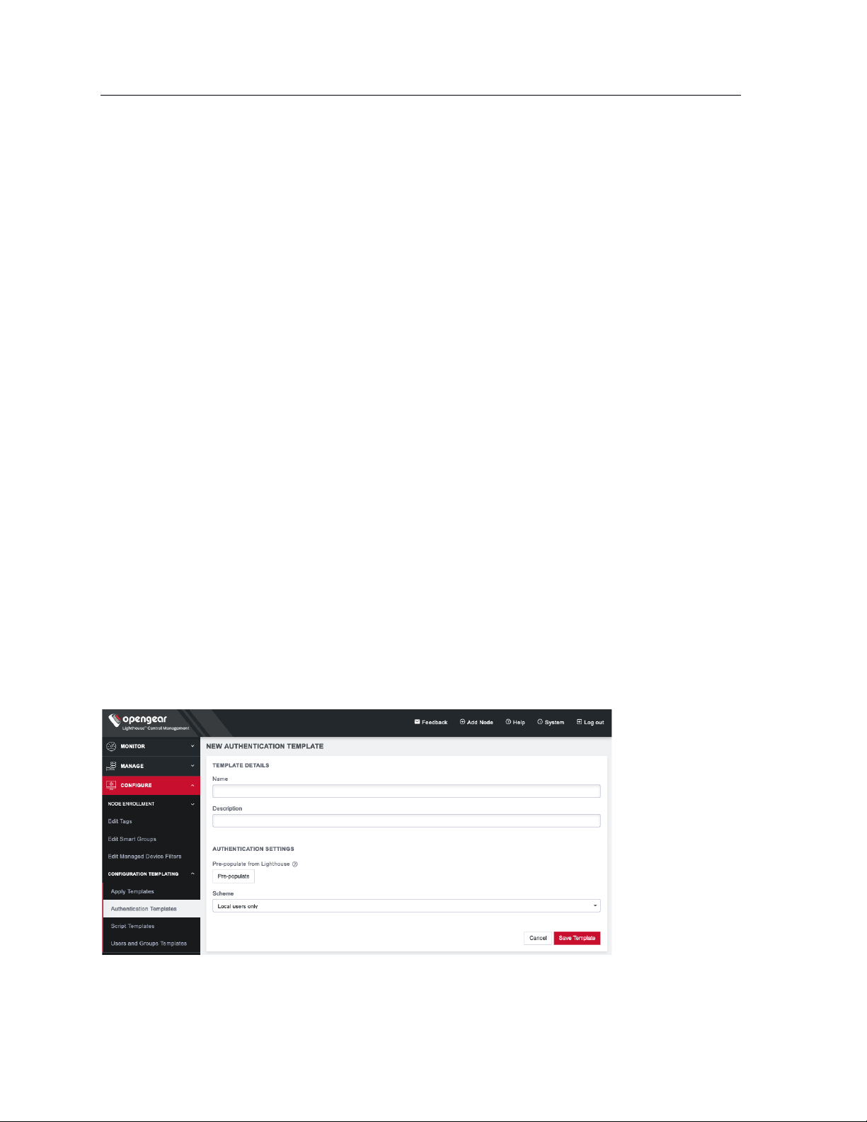
96
Lighthouse User Guide
10.3 Deleting users or groups from a template
To delete a template:
1. Select CONFIGURE > CONFIGURATION TEMPLATING > Users and Groups Templates.
2. Click the Edit button in the Actions section of the template.
3. Click the x button under Actions next to any groups or users which need to be removed.
4. Click Save Template to save the changes.
10.4 Deleting users and groups templates
To delete a template:
1. Select CONFIGURE > CONFIGURATION TEMPLATING > Users and Groups Templates.
2. Click the Delete button next to the template to be removed. The Confirmation alert box appears.
3. Click Yes in the Confirmation dialog. The template is deleted.
10.5 Creating new authentication templates
Only users assigned to the Lighthouse Administrator role can access CONFIGURE > CONFIGURATION
TEMPLATING > Authentication Templates and create authentication templates.
The supported modes are Local, Radius, TACACS+, and LDAP. For example, if an authentication template
is configured to use RADIUS as an authentication source, that corresponds to RADIUSDownLocal with Use
Remote Groups ticked on the downstream node.
To create a new authentication template:
1. Select CONFIGURE > CONFIGURATION TEMPLATING > Authentication Templates.
2. Click the + button. The New Authentication Template page loads.
3. Enter a Name and Description for a template in the Template Details section.
Page 97
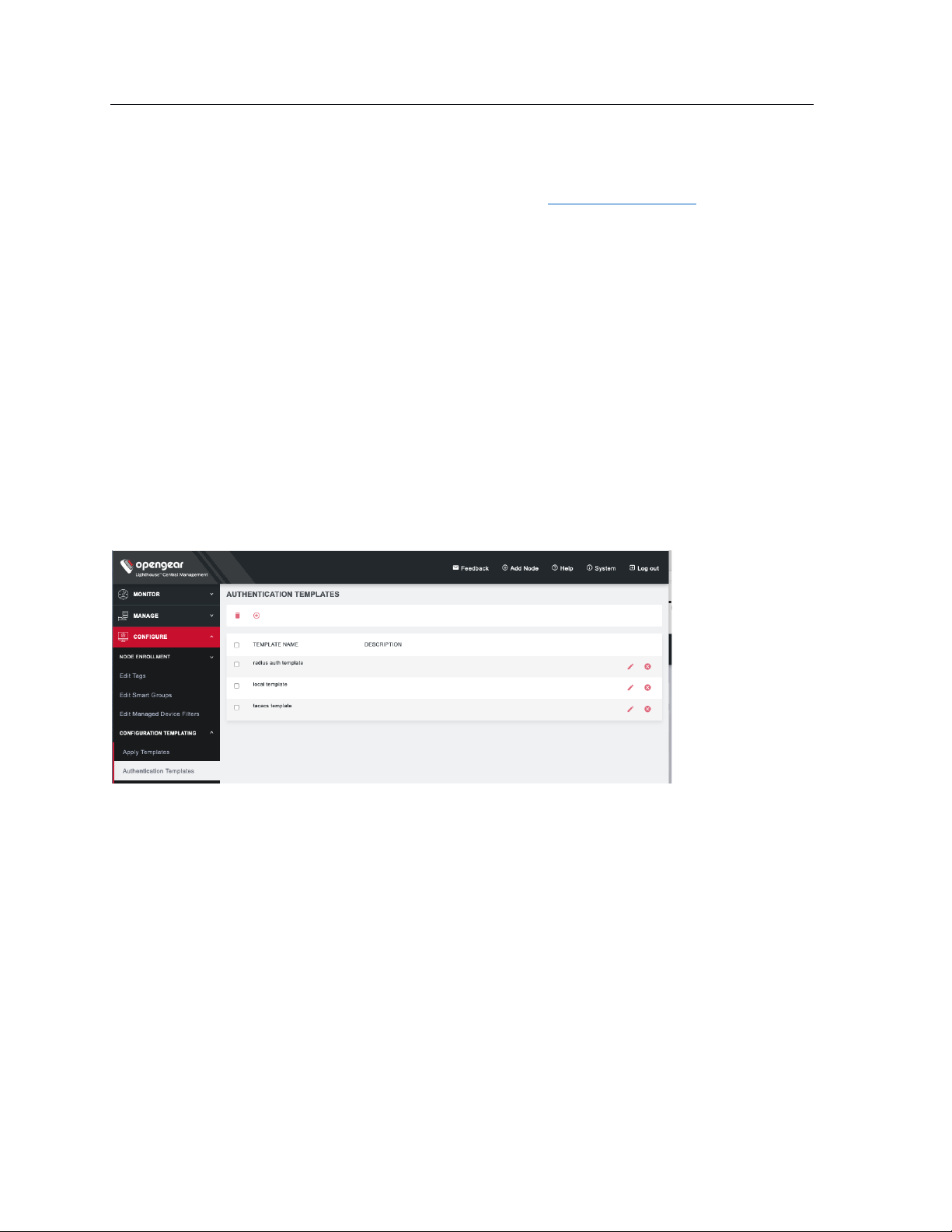
97
Lighthouse User Guide
4. Select a desired Scheme or click Pre-populate to pre-populate a template with the current
Lighthouse remote authentication configuration.
5. Enter or update authentication settings if required. See 8.10 Configuring AAA for an example.
6. Click Save Template.
NOTE: When an authentication template is pushed to a node, the authentication settings at that node are
replaced by the those defined in the authentication template.
NOTE: The authentication templates do not support the full list of settings that the Opengear console
servers support. However, templates can be applied, and then additional settings configured manually.
10.6 Modifying existing authentication templates
The Edit Authentication Template dialog allows the template’s Description and Authentication Settings to
be set and changed.
To modify an existing authentication template:
1. Select CONFIGURE > CONFIGURATION TEMPLATING > Authentication Templates.
2. Click Edit next to the template to be modified. The Edit Authentication Template dialog appears.
Page 98
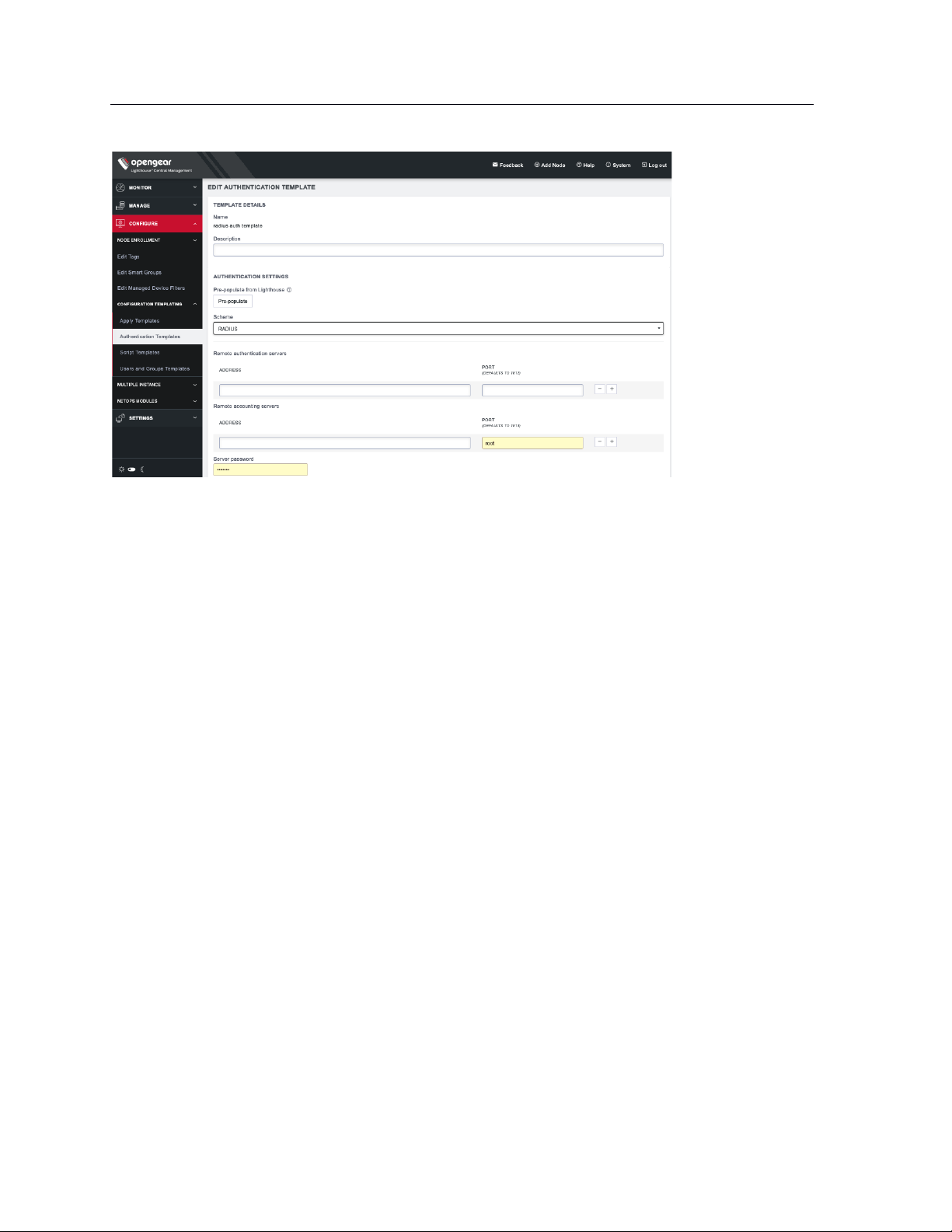
98
Lighthouse User Guide
5. Make required changes.
6. Click Save Template.
10.7 Deleting authentication templates
To delete an authentication template:
1. Select CONFIGURE > CONFIGURATION TEMPLATING > Authentication Templates.
2. Click Delete next to the template to be removed. The Confirmation alert box appears.
3. Click Yes in the Confirmation dialog. The authentication template is deleted.
10.8 Creating new script templates
Users assigned to the Lighthouse Administrator role can access CONFIGURE > CONFIGURATION
TEMPLATING > Script Templates and create script templates.
Script Templates allow the user to upload arbitrary shell scripts to be run on a node. A script may set
additional configuration settings not available in other templates or store additional files onto the node
such as certificates, for example. The uploaded script must have a .sh extension and can’t be more than
1MB in size. Other than those, there are no other restrictions on the script file to be uploaded. Once saved,
the template stores the size and SHA1 checksum of the script. This can be used to verify the script
contents of the template once saved. To apply script templates, the selected nodes need to be running
firmware version 4.1.1 or later.
To create a new script template:
1. Select CONFIGURE > CONFIGURATION TEMPLATING > Script Templates.
2. Click the + button. The New Script Template dialog loads.
Page 99
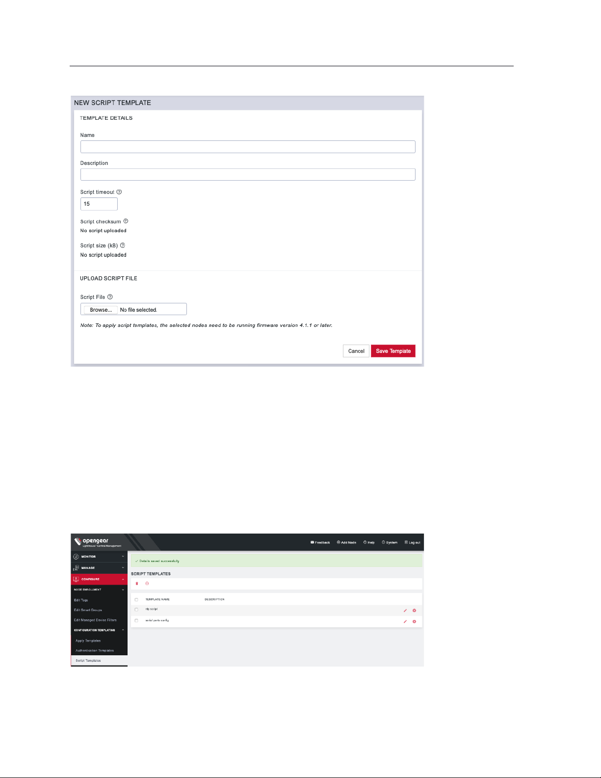
99
Lighthouse User Guide
3. Enter a Name and Description for a template in the Template Details section.
4. To select a script to upload, click Choose file.
5. Click Save Template. Script checksum and Script size are shown after template with uploaded
script is saved.
10.9 Modifying existing script templates
The Edit Script Template dialog allows the template’s Description, Script timeout, and Script File to be
uploaded. To modify an existing script template:
1. Select CONFIGURE > CONFIGURATION TEMPLATING > Script Templates.
2. Click Edit next to the template to be modified. The Edit Script Template dialog appears.
Page 100
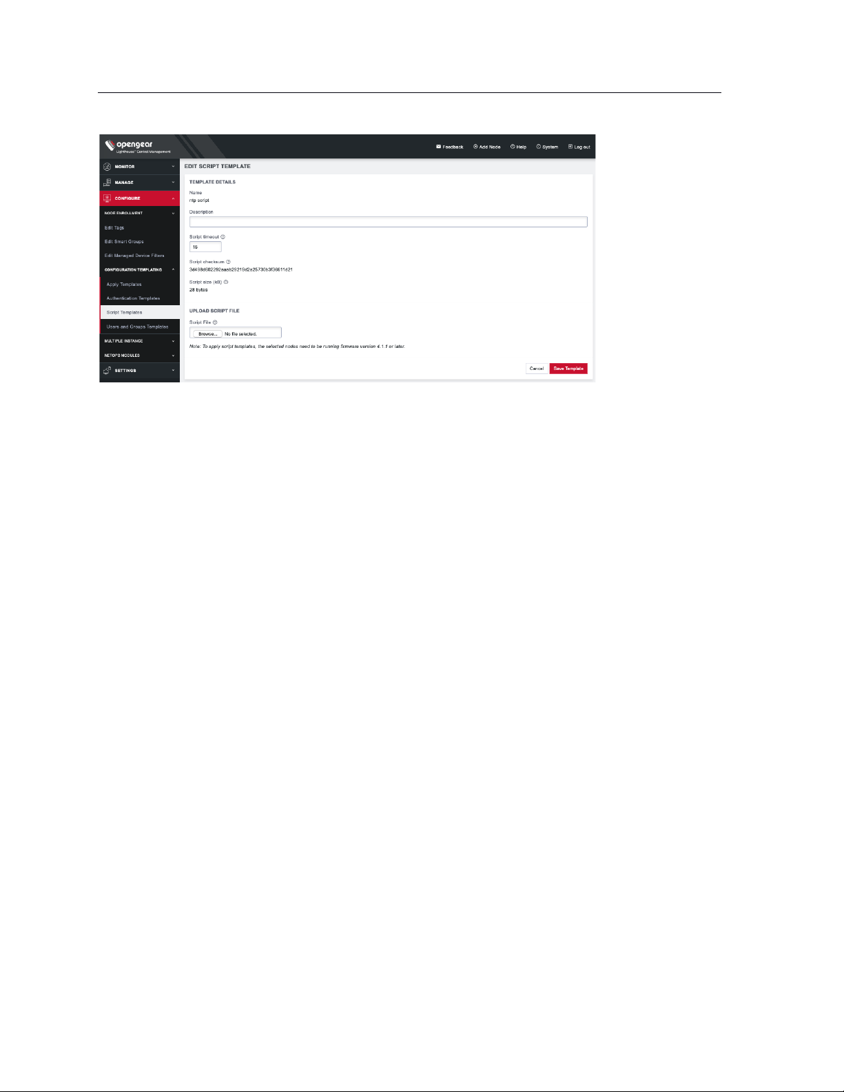
100
Lighthouse User Guide
3. Make required changes.
4. Click Save Template.
10.10 Deleting script templates
To delete a script template completely:
1. Select CONFIGURE > CONFIGURATION TEMPLATING > Script Templates.
2. Click Delete next to the template to be removed. The Confirmation alert box appears.
3. Click Yes in the Confirmation dialog. The script template is deleted.
10.11 Apply Templates
Users with Lighthouse Administrator privileges (i.e. users with the Lighthouse Administrator role or users
who are members of groups with the Lighthouse Administrator role) can access CONFIGURE >
CONFIGURATION TEMPLATING > Apply Templates and execute templates affecting any node.
Users with Node Administrator privileges (i.e. users with the Node Administrator role or users who are
members of groups with the Node Administrator role) can access CONFIGURE > CONFIGURATION
TEMPLATING > Apply Templates and execute templates affecting nodes in Smart Groups linked to their
role.
Apply Templates consists of four stages, each one a step in the overall wizard. The steps are:
1. Select Template.
2. Select Nodes.
3. Preflight. This test run simulates what happens if the template is pushed to the selected nodes.
4. Execution.
To apply a template:
1. Select CONFIGURE > CONFIGURATION TEMPLATING > Apply Templates.
 Loading...