

Page 1

User Manual
ACM5000 & ACM5500 RIM Gateways
IM4000 & IM4200 DCIM Managers
CM4000 DCIM Console Servers
SD4000 Secure Device Server
Rev: 4.5
April 16
th
2012
Advanced Console Server & RIM Gateway User Manual 1
Page 2

Safety
Please take care to follow the safety precautions below when installing and operating the console
server:
- Do not remove the metal covers. There are no operator serviceable components inside. Opening or
removing the cover may expose you to dangerous voltage which may cause fire or electric shock.
Refer all service to Opengear qualified personnel
- To avoid electric shock the power cord protective grounding conductor must be connected through
to ground.
- Always pull on the plug, not the cable, when disconnecting the power cord from the socket.
Do not connect or disconnect the console server during an electrical storm. Also it is recommended you
use a surge suppressor or UPS to protect the equipment from transients.
FCC Warning Statement
This device complies with Part 15 of the FCC rules. Operation of this device is subject to the following
conditions: (1) This device may not cause harmful interference, and (2) this device must accept any
interference that may cause undesired operation.
Page 3

Page 4

Table of Contents
TABLE OF CONTENTS
THIS MANUAL 12
INSTALLATION 16
2.1 Models 16
2.1.1 IM4208-2, IM4216-2, IM4232-2, IM4248-2 and IM4216-34 kit components 17
2.1.2 IM4004-5 kit components 18
2.1.3 CM4116, CM4132 and CM4148 kit components 18
2.1.4 CM4008 kit components 19
2.1.5 CM4001 and SD4002 kit components 19
2.1.6 SD4001 kit components 20
2.1.7 ACM5000 kit components 20
2.1.8 ACM5500 kit components 21
2.2 Power Connection 21
2.2.1 IM4216-34-DAC, IM4208-2-DAC, IM4216-2-DAC, IM4232-2-DAC and IM4248-2-DAC power 21
2.2.2 CM4116-SAC, CM4132-SAC and CM4148-SAC power 21
2.2.3 IM4004-5 and CM4008 power 22
2.2.4 CM4001/ SD4002 and SD4001 power 22
2.2.5 ACM500x, ACM500x-2, ACM500x-M/W/I/G and ACM500x-SDC power 22
2.2.6 ACM5508-2-M, ACM5508-2-I, ACM5504-5-G-I, ACM5504-5-GV-I and ACM5504-2-P power 23
2.2.7 IM4216-34-DDC, IM4208-2-DDC, IM4216-2-DDC, IM4232-2-DDC and IM4248-2-DDC power 23
2.3 Network Connection 24
2.4 Serial Port Connection 25
2.4.1 Opengear Classic RJ45 pinout (option –X0) 26
2.4.2 Cisco Rolled (Cyclades) RJ45 pinout (option -X1) 26
2.4.3 Cisco RJ45 pinout (option -X2) 27
2.5 USB Port Connection 27
2.6 Fitting Cellular SIM and Antennas 27
2.6.1 ACM5004-G/G-I and ACM5504-5-G-I SIM 28
2.6.2 ACM5004-G/G-I/GV and ACM5504-5-G-I antenna 28
2.6.3 IM42xx-2-DAC-X2-G and IM42xx-2-DAC-X0-G 28
2.6.4n External USB cellular modems 29
2.7 Digital I/O and Environmental Sensors 29
SYSTEM CONFIGURATION 30
3.1 Management Console Connection 30
3.1.1 Connected computer set up 30
3.1.2 Browser connection 31
3.2 Administrator Password 32
3.2.1 Set up new administrator 33
3.3 Network IP Address 34
3.3.1 IPv6 configuration 35
3.3.2 Dynamic DNS (DDNS) configuration 35
3.4 System Firewall - Service Access 36
3.5 Communications Software 39
3.5.1 SDT Connector 39
3.5.2 PuTTY 40
3.5.3 SSHTerm 41
3.6 Management Network Configuration 41
3.6.1 Enable the Management LAN 41
3.6.2 Configure the DHCP server 43
3.6.3 Select Failover or broadband OoB 44
3.6.4 Aggregating the network ports 45
3.6.5 Wireless LAN 46
3.6.6 Static routes 48
SERIAL PORT, HOST, DEVICE & USER CONFIGURATION 50
4 Console Server & RIM Gateway User Manual
Page 5

User Manual
4.1 Configure Serial Ports 50
4.1.1 Common Settings 51
4.1.2 Console Server Mode 52
4.1.3 SDT Mode 56
4.1.4 Device (RPC, UPS, EMD) Mode 56
4.1.5 Terminal Server Mode 57
4.1.6 Serial Bridging Mode 57
4.1.7 Syslog 58
4.1.8 NMEA Streaming 58
4.2 Add/ Edit Users 59
4.2.1 Set up new Group 60
4.2.1 Set up new Users 61
4.3 Authentication 63
4.4 Network Hosts 63
4.5 Trusted Networks 64
4.6 Serial Port Cascading 65
4.6.1 Automatically generate and upload SSH keys 66
4.6.2 Manually generate and upload SSH keys 67
4.6.3 Configure the slaves and their serial ports 68
4.6.4 Managing the slaves 69
4.7 Serial Port Redirection (PortShare) 70
4.8 Managed Devices 71
4.9 IPsec VPN 73
4.9.1 Enable the VPN gateway 73
4.10 OpenVPN 75
4.10.1 Enable the OpenVPN 76
4.10.2 Configure as Server or Client 77
4.10.3 Windows OpenVPN Client and Server set up 80
4.11 PPTP VPN 84
4.11.1 Enable the PPTP VPN server 84
4.11.2 Add a PPTP user 86
4.11.3 Set up a remote PPTP client 86
4.12 Call Home 88
4.12.1 Set up Call Home candidate 88
4.12.2 Accept Call Home candidate as Managed Console Server on CMS 89
4.12.3 Calling Home to a generic central SSH server 90
FIREWALL, FAILOVER & OoB ACCESS 92
5.1 Dialup Modem Connection 92
5.2 OoB Dial-In Access 92
5.2.1 Configure Dial-In PPP 92
5.2.2 Using SDT Connector client 95
5.2.3 Set up Windows XP/ 2003/Vista/7 client 95
5.2.4 Set up earlier Windows clients 95
5.2.5 Set up Linux clients 96
5.3 Dial-Out Access 96
5.3.1 Always-on dial-out 96
5.3.2 Failover dial-out 97
5.4 OoB Broadband Ethernet Access 99
5.5 Broadband Ethernet Failover 100
5.6 Cellular Modem Connection 101
5.6.1 Connect to the GSM HSUPA/UMTS carrier network 102
5.6.2 Connect to the CDMA EV-DO carrier network 103
5.6.3 Verify cellular connection 105
5.7 Cellular Operation 107
5.7.1 OoB access set up 107
5.7.2 Cellular failover setup 108
Advanced Console Server & RIM Gateway User Manual 5
Page 6

Table of Contents
5.7.3 Cellular routing 109
5.7.4 Cellular CSD dial-in setup 109
5.8 Firewall & Forwarding 110
5.8.1 Configuring network forwarding and IP masquerading 111
5.8.2 Configuring client devices 113
5.8.3 Port / Protocol forwarding 115
5.8.4 Firewall rules 116
SSH TUNNELS & SDT CONNECTOR 120
6.1 Configuring for SSH Tunneling to Hosts 121
6.2 SDT Connector Client Configuration 121
6.2.1 SDT Connector client installation 121
6.2.2 Configuring a new gateway in the SDT Connector client 122
6.2.3 Auto-configure SDT Connector client with the user’s access privileges 124
6.2.4 Make an SDT connection through the gateway to a host 124
6.2.5 Manually adding hosts to the SDT Connector gateway 125
6.2.6 Manually adding new services to the new hosts 126
6.2.7 Adding a client program to be started for the new service 128
6.2.8 Dial in configuration 129
6.3 SDT Connector to Management Console 130
6.4 SDT Connector - telnet or SSH connect to serially attached devices 131
6.5 Using SDT Connector for out-of-band connection to the gateway 132
6.6 Importing (and exporting) preferences 133
6.7 SDT Connector Public Key Authentication 134
6.8 Setting up SDT for Remote Desktop access 134
6.8.1 Enable Remote Desktop on the target Windows computer to be accessed 134
6.8.2 Configure the Remote Desktop Connection client 136
6.9 SDT SSH Tunnel for VNC 138
6.9.1 Install and configure the VNC Server on the computer to be accessed 138
6.9.2 Install, configure and connect the VNC Viewer 140
6.10 Using SDT to IP connect to hosts that are serially attached to the gateway 141
6.10.1 Establish a PPP connection between the host COM port and console server 142
6.10.2 Set up SDT Serial Ports on console server 144
6.10.3 Set up SDT Connector to ssh port forward over the console server Serial Port 145
6.11 SSH Tunneling using other SSH clients (e.g. PuTTY) 145
ALERTS, AUTOMATED RESPONSE AND LOGGING 150
7.1 Configure Auto-Response 150
7.2 Check Conditions 152
7.2.1 Environmental 152
7.2.2 Alarms and Digital Inputs 153
7.2.3 UPS / Power Supply 153
7.2.4 UPS Status 154
7.2.5 Serial Login/Logout 154
7.2.6 ICMP Ping 155
7.2.7 Cellular Data 156
7.2.8 Custom Check 156
7.2.9 SMS Command 157
7.3 Trigger Actions 158
7.3.1 Send Email 158
7.3.2 Send SMS 158
7.3.3 Perform RPC Action 159
7.3.4 Run Custom Script 159
7.3.5 Send SNMP Trap 159
7.3.6 Send Nagios Event 159
7.4 Resolve Actions 160
7.5 Configure SMTP, SMS, SNMP and/or Nagios service for alert notifications 160
7.5.1 Send Email alerts 160
6 Console Server & RIM Gateway User Manual
Page 7

User Manual
7.5.2 Send SMS alerts 161
7.5.3 Send SNMP Trap alerts 162
7.5.4 Send Nagios Event alerts 164
7.6 Logging 164
7.6.1 Log storage 164
7.6.2 Serial port logging 165
7.6.3 Network TCP and UDP port logging 166
7.6.4 Auto-Response event logging 166
7.6.5 Power device logging 167
POWER, ENVIRONMENT & DIGITAL I/O 168
8.1 Remote Power Control (RPC) 168
8.1.1 RPC connection 168
8.1.2 RPC access privileges and alerts 172
8.1.3 User power management 172
8.1.4 RPC status 172
8.2 Uninterruptible Power Supply Control (UPS) 174
8.2.1 Managed UPS connections 174
8.2.2 Remote UPS management 177
8.2.3 Controlling UPS powered computers 178
8.2.4 UPS alerts 179
8.2.5 UPS status 179
8.2.6 Overview of Network UPS Tools (NUT) 181
8.3 Environmental Monitoring 183
8.3.1 Connecting the EMD and its sensors 183
8.3.2 Connecting sensors to ACM5000 and ACM5500s 184
8.3.3 Adding EMDs and configuring the sensors 186
8.3.4 Environmental alerts 188
8.3.5 Environmental status 188
8.4 Digital I/O Ports 189
8.4.1 Digital I/O Output Configuration 189
8.4.2 Digital I/O Input Configuration 190
8.4.3 High Voltage Outputs 190
AUTHENTICATION 192
9.1 Authentication Configuration 192
9.1.1 Local authentication 192
9.1.2 TACACS authentication 192
9.1.3 RADIUS authentication 193
9.1.4 LDAP authentication 194
9.1.5 RADIUS/TACACS user configuration 195
9.1.6 Group support with remote authentication 196
9.1.7 Remote groups with RADIUS authentication 197
9.1.8 Remote groups with LDAP authentication 198
9.1.9 Idle timeout 200
9.1.10 Kerberos authentication 200
9.1.11 Authentication testing 201
9.2 PAM (Pluggable Authentication Modules) 201
9.3 SSL Certificate 202
NAGIOS INTEGRATION 206
10.1 Nagios Overview 206
10.2 Central management and setting up SDT for Nagios 207
10.2.1 Set up central Nagios server 208
10.2.2 Set up distributed Opengear console servers 208
10.2.3 Set up SDT for Nagios on the central Nagios server 210
10.2.4 Set up the clients 211
10.3 Configuring Nagios distributed monitoring 212
10.3.1 Enable Nagios on the console server 213
Advanced Console Server & RIM Gateway User Manual 7
Page 8

Table of Contents
10.3.2 Enable NRPE monitoring 214
10.3.3 Enable NSCA monitoring 214
10.3.4 Configure selected Serial Ports for Nagios monitoring 215
10.3.5 Configure selected Network Hosts for Nagios monitoring 216
10.3.6 Configure the upstream Nagios monitoring host 217
10.4 Advanced Distributed Monitoring Configuration 217
10.4.1 Sample Nagios configuration 217
10.4.2 Basic Nagios plug-ins 220
10.4.3 Additional plug-ins 220
10.4.4 Number of supported devices 222
10.4.5 Distributed Monitoring Usage Scenarios 223
SYSTEM MANAGEMENT 226
11.1 System Administration and Reset 226
11.2 Upgrade Firmware 227
11.3 Configure Date and Time 228
11.4 Configuration Backup 229
11.5 Delayed Configuration Commit 231
11.6 FIPS Mode 232
STATUS REPORTS 234
12.1 Port Access and Active Users 234
12.2 Statistics 234
12.3 Support Reports 235
12.4 Syslog 236
12.5 Dashboard 236
12.5.1 Configuring the Dashboard 237
12.5.2 Creating custom widgets for the Dashboard 238
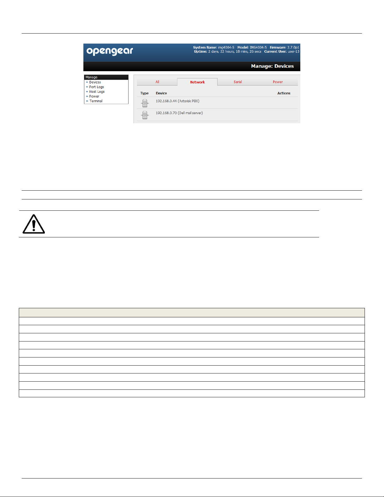
MANAGEMENT 240
13.1 Device Management 240
13.2 Port and Host Logs 240
13.3 Terminal Connection 240
13.3.1 Web Terminal 241
13.3.2 SDT Connector access 242
13.4 Power Management 243
CONFIGURATION FROM THE COMMAND LINE 244
14.1 Accessing config from the command line 244
14.1.1 Serial Port configuration 246
14.1.2 Adding and removing Users 249
14.1.3 Adding and removing user Groups 250
14.1.4 Authentication 251
14.1.5 Network Hosts 251
14.1.6 Trusted Networks 253
14.1.7 Cascaded Ports 253
14.1.8 UPS Connections 254
14.1.9 RPC Connections 255
14.1.10 Environmental 256
14.1.11 Managed Devices 256
14.11.12 Port Log 257
14.1.13 Alerts 257
14.1.14 SMTP & SMS 260
14.1.15 SNMP 260
14.1.16 Administration 261
14.1.17 IP settings 261
14.1.18 Date & Time settings 262
14.1.19 Dial-in settings 262
14.1.20 DHCP server 263
14.1.21 Services 264
8 Console Server & RIM Gateway User Manual
Page 9

User Manual
14.1.22 NAGIOS 264
ADVANCED CONFIGURATION 266
15.1 Custom Scripting 266
15.1.1 Custom script to run when booting 266
15.1.2 Running custom scripts when alerts are triggered 266
15.1.3 Example script - Power cycling on pattern match 267
15.1.4 Example script - Multiple email notifications on each alert 268
15.1.5 Deleting configuration values from the CLI 268
15.1.6 Power cycle any device upon a ping request failure 270
15.1.7 Running custom scripts when a configurator is invoked 272
15.1.8 Backing-up the configuration and restoring using a local USB stick 272
15.1.9 Backing-up the configuration off-box 273
15.2 Advanced Portmanager 274
15.2.1 Portmanager commands 274
15.2.2 External Scripts and Alerts 275
15.3 Raw Access to Serial Ports 276
15.3.1 Access to serial ports 276
15.3.2 Accessing the console/modem port 276
15.4 IP- Filtering 277
15.5 SNMP Status Reporting 277
15.5.1 Retrieving status information using SNMP 278
15.5.2 Check firewall rules 278
15.5.3 Enable SNMP Service 279
15.5.4 /etc/config/snmpd.conf 284
15.5.5 Adding multiple remote SNMP managers 285
15.6 Secure Shell (SSH) Public Key Authentication 286
15.6.1 SSH Overview 286
15.6.2 Generating Public Keys (Linux) 286
15.6.3 Installing the SSH Public/Private Keys (Clustering) 287
15.6.4 Installing SSH Public Key Authentication (Linux) 287
15.6.5 Generating public/private keys for SSH (Windows) 289
15.6.6 Fingerprinting 290
15.6.7 SSH tunneled serial bridging 291
15.6.8 SDT Connector Public Key Authentication 293
15.7 Secure Sockets Layer (SSL) Support 294
15.8 HTTPS 294
15.8.1 Generating an encryption key 294
15.8.2 Generating a self-signed certificate with OpenSSL 294
15.8.3 Installing the key and certificate 295
15.8.4 Launching the HTTPS Server 295
15.9 Power Strip Control 295
15.9.1 The PowerMan tool 295
15.9.2 The pmpower tool 297
15.9.3 Adding new RPC devices 297
15.10 IPMItool 298
15.11 Custom Development Kit (CDK) 301
15.12 Scripts for Managing Slaves 301
15.13 SMS Server Tools 302
15.14 Multicast 302
APPENDIX A: Linux Commands & Source Code 304
APPENDIX B: Hardware Specification 310
APPENDIX C: Safety & Certifications 312
Appendix D: Connectivity, TCP Ports & Serial I/O 314
APPENDIX E: TERMINOLOGY 324
APPENDIX F: END USER LICENSE AGREEMENTS 328
APPENDIX G: SERVICE & STANDARD WARRANTY 334
Advanced Console Server & RIM Gateway User Manual 9
Page 10

Table of Contents
10 Console Server & RIM Gateway User Manual
Page 11

Page 12

Introduction
THIS MANUAL
This Users Manual walks you through installing and configuring the following Opengear product lines:
- ACM5504-5-G-I, ACM5504-2-P, ACM5508-2-M and ACM5008-2-P Remote Infrastructure Management (RIM)
gateways
- ACM5002, ACM5004, ACM5004-2, ACM5004-G, ACM5004-I, ACM5003-M & ACM5003-W Remote Infrastructure
Management (RIM) gateways (with –SDC, -E and -F options) and ACM5004-G/GV (with –SDC and -E options) &
ACM5005-G-I Cellular Routers
- IM4004-5 & IM4216-34-DAC (or DDC) Management Gateways
- IM4248-2-DAC (or DDC), IM4232-2-DAC (DDC), IM4216-2-DAC (DDC) & IM4208-2-DAC Infrastructure Managers
- CM4001, CM4008, CM4116-SAC, CM4116-SAC & CM4148-SAC Console Servers
- SD4001, SD4002 Secure Device Server
Each of these products is referred to generically in this manual as a console server. Where appropriate product groups
may be referred to as RIM gateways or cellular routers or by specific product line name or product group (e.g. IM4200
family, ACM5500).
Manual Organization
This manual contains the following chapters:
1. Introduction An overview of the features of the console server and information on this manual
2. Installation Physical installation of the console server and the interconnecting of managed devices
3. System Configuration Covers initial installation and configuration of the console server on the network and the
services that will be supported
4. Serial & Network Covers configuring serial ports and connected network hosts, and setting up users
5. Firewall, Failover & OoB Describes setting up the firewall router functions and the high availability access features
of the console server
6. Secure Tunneling Covers secure remote access using SSH and configuring for RDP, VNC, HTTP, HTTPS
etc access to network and serially connected devices
7. Auto Response and Logs Explains the setting up of local and remote event/ data logs and configuring auto-
response actions to trigger events
8. Power & Environment Management of USB, serial and network attached power strips and UPS supplies. EMD
environmental sensor configuration
9. Authentication All access to the console server requires usernames and passwords which are locally or
externally authenticated
10. Nagios Integration Setting Nagios central management with SDT extensions and configuring the console
server as a distributed Nagios server
11. System Management Covers access to and configuration of services to be run on the console server
12. Status Reports View a dashboard summary and detailed status and logs of serial and network connected
devices (ports, hosts, power and environment)
13. Management Includes port controls and reports that can accessed by Users
14 Basic Configuration Command line installation and configuration using the config command
15. Advanced Config Advanced command line configuration activities using Linux commands
The latest update of this manual can be found online at www.opengear.com/download.html
12 Console Server & RIM Gateway User Manual
Page 13
User Manual
Types of users
The console server supports two classes of users:
I. Firstly there are the administrative users who will be authorized to configure and control the console server; and to
access and control all the connected devices. These administrative users will be set up as members of the admin user
group and any user in this class is referred to generically in this manual as the Administrator. An Administrator can
access and control the console server using the config utility, the Linux command line or the browser based
Management Console. By default the Administrator has access to all services and ports to control all the serial
connected devices and network connected devices (hosts).
II. The second class of users embraces those who have been set up by the Administrator with specific limits of their
access and control authority. These users are set up as members of the users user group (or some other user groups
the Administrator may have added). They are only authorized to perform specified controls on specific connected
devices are referred to as Users. These Users (when authorized) can access serial or network connected devices; and
control these devices using the specified services (e.g. Telnet, HHTPS, RDP, IPMI, Serial over LAN, Power Control).
An authorized User also has a limited view the Management Console and can only access authorized configured
devices and review port logs.
In this manual, when the term user (lower case) is used, it is referring to both the above classes of users. This document
also uses the term remote users to describe users who are not on the same LAN segment as the console server. These
remote users may be Users, who are on the road connecting to managed devices over the public Internet, or it may be an
Administrator in another office connecting to the console server itself over the enterprise VPN, or the remote user may be
in the same room or the same office but connected on a separate VLAN to the console server.
Management Console
The Management Console runs in a browser and provides a view of the console server and all the connected devices.
Administrators can use the Management Console, either locally or from a remote location, to manage the console server,
users, ports, hosts, power devices and associated logs and alerts.
A User can also use the Management Console, but has limited menu access to control select devices, review their logs
and access them using the in-built Web terminal or control power to them.
Advanced Console Server & RIM Gateway User Manual 13
Page 14
Introduction
Text presented like this highlights important issues and it is essential you read and
take head of these warnings
The console server runs an embedded Linux operating system, and experienced Linux and UNIX users may prefer to
undertake configuration at the command line. You can command line access by dial-in or directly connecting to the
console server’s serial console/modem port, or by using ssh or Telnet to connect to the console server over the LAN, or
with PPTP, IPsec or OpenVPN.
Manual Conventions
This manual uses different fonts and typefaces to show specific actions:
Note Text presented like this indicates issues to take note of
Text presented with an arrow head indent indicates an action you should take as part of the procedure
Bold text indicates text that you type, or the name of a screen object (e.g. a menu or button) on the Management
Console.
Italic text is also used to indicate a text command to be entered at the command line level.
Publishing history
Date Revision Update details
Jan 2010 3.8.4 SD4001 product
Mar 2010 3.8.5 ACM5004-G, fixed Failover details and added DDNS
June 2010 3.9 V3.1 (shadow password, deg F, SNMP, SMS gateway) and ACM5004-I
Aug 2010 3.9.1 V3.2 (OpenVPN, Zenoss, config commit, Call Home)
Dec 2010 4.0 V3.3 (Firewall router, Web Terminal, SNMP updates)
June 2011 4.1 V3.4 (GPS support, SNMP traffic monitoring and IPv6, 32 port models, SMS over cellular)
Oct 2011 4.2 V3.5 (Auto Response, IM4004-5)
Nov 2011 4.3 V3.5.2u2 (PPTP, GRE, ext Groups, FTP server, multiple dial-in, pmshell update). Add IM4216-34
Feb 2012 4.4 V3.5.2u3 (Kerberos, Cisco RJ in SD4000, Add ACM5500, Remove KCS)
April 2012 4.5 V3.5.2u13 (Cellular redial,
14 Console Server & RIM Gateway User Manual
Page 15
Proper back-up systems and necessary safety devices should be utilized to protect
against injury, death or property damage due to system failure. Such protection is the
responsibility of the user.
This console server device is not approved for use as a life-support or medical system.
Any changes or modifications made to this console server device without the explicit
approval or consent of Opengear will void Opengear of any liability or responsibility of
injury or loss caused by any malfunction.
This equipment is for indoor use and all the communication wirings are limited to
inside of the building.
User Manual
Copyright
©Opengear Inc. 2012. All Rights Reserved.
Information in this document is subject to change without notice and does not represent a commitment on the part of
Opengear. Opengear provides this document “as is,” without warranty of any kind, either expressed or implied, including,
but not limited to, the implied warranties of fitness or merchantability for a particular purpose.
Opengear may make improvements and/or changes in this manual or in the product(s) and/or the program(s) described in
this manual at any time. This product could include technical inaccuracies or typographical errors. Changes are
periodically made to the information herein; these changes may be incorporated in new editions of the publication.
Advanced Console Server & RIM Gateway User Manual 15
Page 16

Chapter 2: Installation
Model
Serial
Ports
USB
Ports
Network
Ports
Console
Port
Modem
(V.92)
Wireless
(Cell & WIFI)
Environment
Sensors
RJ
Pinout
Power
ACM5002
2 1 1 - -
-
Temp/probes
02
Ext AC/DC
ACM5004
4 1 1 - -
-
Temp/probes
02
Ext AC/DC
ACM5004-2
4 2 2 - -
-
Temp/probes
02
Ext AC/DC
ACM5003-M
3 1 1
-
Internal
-
Temp/probes
02
Ext AC/DC
ACM5003-W
3 1 1 - -
802.11
Temp/probes
02
Ext AC/DC
ACM5004-G/GV
4 1 1 - -
3G Cell
Temp/probes
02
Ext AC/DC
ACM5004-G-I
4* 1 1 - -
3G Cell
Temp & DI/O
02
Ext AC/DC
ACM5004-2-I
4* 2 2 - -
-
Temp & DI/O
02
Ext AC/DC
ACM5504-2-P
4 2 2 - - - -
02
PoE
ACM5504-5-G-I
4* 2 5 - -
3G Cell
-
02
Ext AC/DC
ACM5508-2-I
8* 2 2 - - - -
02
Ext AC/DC
ACM5508-2-M
8 2 2
-
Internal - -
02
Ext AC/DC
IM4248-2-DAC
48
3** 2 1
Internal
Opt ***
-
00/01/02
Dual AC
IM4248-2-DDC
48
3** 2 1
Internal
Opt ***
-
00/01/02
Dual DC
IM4232-2-DAC
32
3** 2 1
Internal
Opt ***
-
00/01/02
Dual AC
IM4232-2-DDC
32
3** 2 1
Internal
Opt ***
-
00/01/02
Dual DC
IM4216-2-DAC
16
3** 2 1
Internal
Opt ***
-
00/01/02
Dual AC
IM4216-2-DDC
16
3** 2 1
Internal
Opt ***
-
00/01/02
Dual DC
IM4208-2-DAC
8
3** 2 1
Internal
Opt ***
-
00/01/02
Dual AC
IM4208-2-DDC
8
3** 2 1
Internal
Opt ***
-
00/01/02
Dual DC
IM4216-34-DAC
16
3**
34
1
Internal
Opt ***
-
02
Dual AC
IM4004-5
4 2 5
1
External
Ext Cell
-
00
Ext AC/DC
CM4148-SAC
48 - 1 1 - - -
00
Single AC
CM4132-SAC
32 - 1 1 - - -
00
Single AC
CM4116-SAC
16 - 1 1 - - -
00
Single AC
CM4008
8 - 1 1 - - -
00
Ext AC/DC
CM4001
1 - 1 1 - - -
00
Ext AC/DC
SD4001
1* - 1 - - - -
DB9
Ext AC/DC
SD4002
2* - 1 - - - -
DB9
Ext AC/DC
INSTALLATION
This chapter describes how to install the console server hardware and connect it to controlled devices.
2.1 Models
There are multiple families and models, each with a different number of network/ serial /USB ports or power supply and
wireless configurations:
* RS4232/422/485. All other models have RS232 serial
** These models have 2x USB2.0 and 1xUSB1.1 port. All other models have USB2.0 ports
*** Internal cellular available as an option
The initial IM42xx models were superseded by IM42xx-X models (to provide additional flash and USB support).
The IMG4004-5 is superseded by IM4004-5 with additional flash and USB support.
The IMG4216-25 is superseded by IM4216-34 with additional Ethernet ports, flash and USB ports.
The SD4008 is end of life (EoL) and is replaced with ACM5508-2-I.
The KCS6000 family is EoL
16 Console Server & RIM Gateway User Manual
Page 17
Feature by
Model/Family
DHCP
DDNS
Mgt
LAN
WLAN
OoB
Failover
Auto
Response
Internal
Flash
FIPS
FTP &
TFTP
IPsec, PPTP
& OpenVPN
ACM500x-x-x
yes
yes
yes**
if -W
yes
yes
2GB*
yes
yes
yes
ACM550x-x-x
yes
yes
yes**
no
yes
yes
4GB
yes
yes
yes
CM4xxx
no
no
no
no
no
yes
no
no
no
no
IM4004-5
yes
yes
yes
no
yes
yes
4GB
yes
yes
yes
IM4216-34
yes
yes
yes
no
yes
yes
16GB
yes
yes
yes
IM42xx-2-Xx
yes
yes
yes
no
yes
yes
16GB
yes
yes
yes
SD400x
no
no
no
no
no
yes
no
no
no
no
To avoid physical and electrical hazard please read Appendix C on Safety
Part # 509006
Part # 509007
Part # 509008
Part # 509009
IM4216-2 Infrastructure Manager
IM4248-2 Infrastructure Manager
IM4208-2 Infrastructure Manager
IM4216-34 Management Gateway
Part # 440016
2 x Cable UTP Cat5 blue
Part # 319000
and 319001
Connector DB9F-RJ45S straight and DB9F-RJ45S
cross-over
Part # 440001
Dual IEC AC power cord (DAC models only)
Part # 539001
Quick Start Guide and CD-ROM
User Manual
The various product families support different software features:
* Option for ACM5002. ACM5003-M and ACM5004 only
** ACM500x-2, ACM550x-2 & ACM5504-5-G-I models only
The sections below show the components shipped with each of these models.
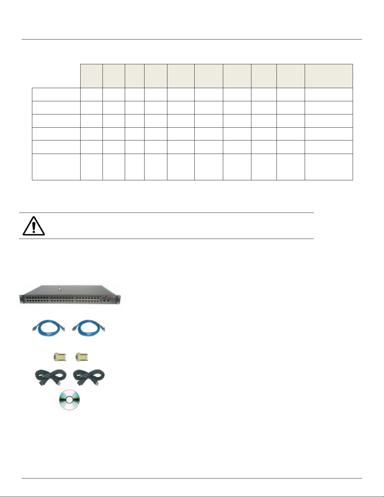
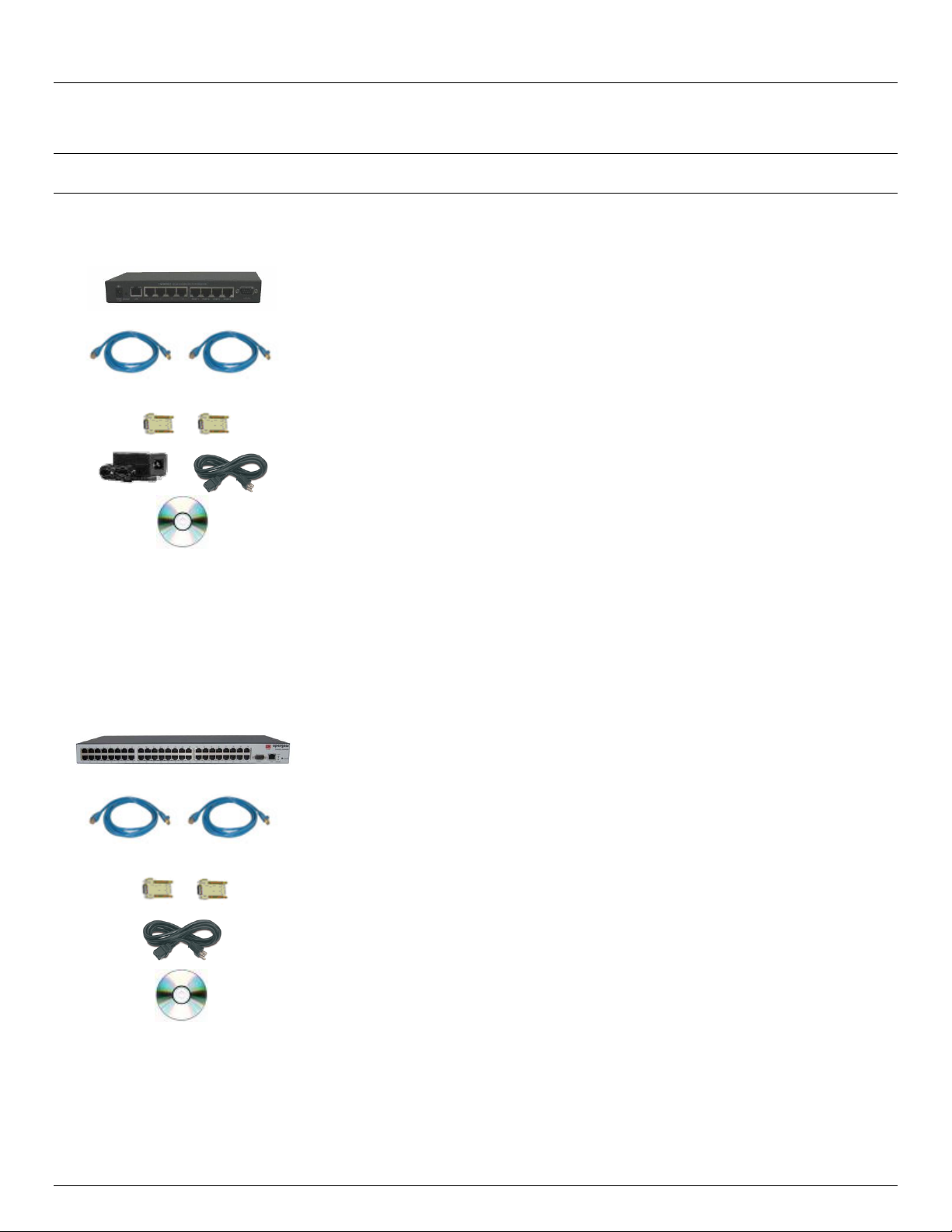
2.1.1 IM4208-2, IM4216-2, IM4232-2, IM4248-2 and IM4216-34 kit components
Unpack your IM42xx (IM4208-2, IM4216-2, IM4232-2, IM4248-2 Infrastructure Manager or IM4216-34
Management Gateway) kit and verify you have all the parts shown above, and that they all appear in good
working order
If you are installing your IM42xx in a rack you will need to attach the rack mounting brackets supplied with the
Advanced Console Server & RIM Gateway User Manual 17
unit, and install the unit in the rack. Take care to head the Safety Precautions listed in Appendix C
Page 18
Chapter 2: Installation
Part # 509010
IM4004-5 Management Gateway
Part # 440016
2 x Cable UTP Cat5 blue
Part # 319000
and 319001
Connector DB9F-RJ45S straight and DB9F-RJ45S
cross-over
Part # 450006
and 440001
Power Supply 5VDC 2.0A
IEC Socket and AC power cable
Part #539000
Quick Start Guide and CD-ROM
Part # 509001
Part # 509002
CM4116 Console Manager
CM4148 Console Server
Part # 440016
2 x Cable UTP Cat5 blue
Part # 319000
and 319001
Connector DB9F-RJ45S straight and DB9F-RJ45S
cross-over
Part # 440001
IEC AC power cord
Part # 539001
Quick Start Guide and CD-ROM
Proceed to connect your IM42xx to the network, to the serial ports of the controlled devices, and to power as
outlined below
Note The IM4216-2-DDC, IM4232-2-DDC, IM4248-2-DDC and IM4216-34-DDC products are DC powered and the kits
do not include an IEC AC power cord
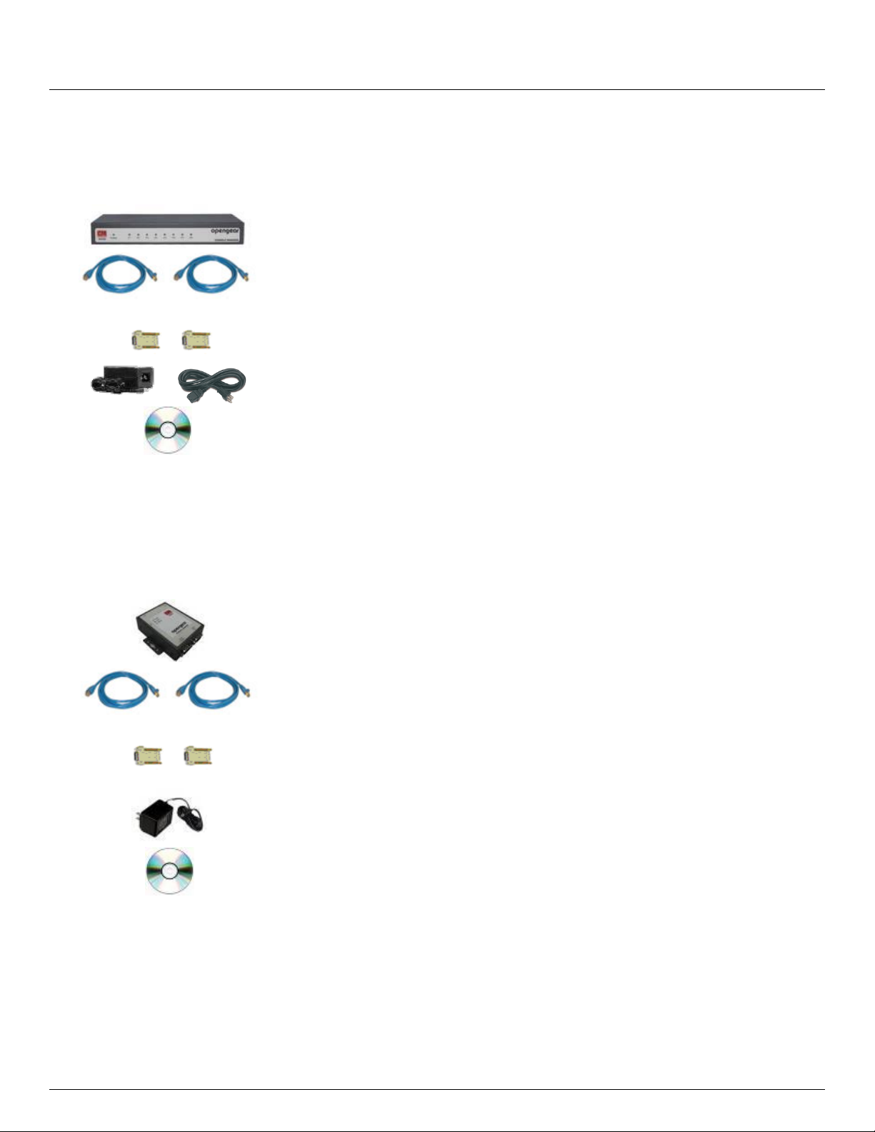
2.1.2 IM4004-5 kit components
Unpack your IM4004-5 kit and verify you have all the parts shown above, and that they all appear in good working
order
Proceed to connect your IM4004-5 to the network, the serial ports, USB ports and LAN ports of the controlled
devices and to the AC power as shown below
2.1.3 CM4116, CM4132 and CM4148 kit components
Unpack your CM4116 (or CM4132/CM4148) kit and verify you have all the parts shown above, and that they all
appear in good working order
If you are installing your CM4116 (or CM4132/CM4148) in a rack you will need to attach the rack mounting
brackets supplied with the unit, and install the unit in the rack. Take care to head the Safety Precautions listed in
Appendix C
18 Console Server & RIM Gateway User Manual
Page 19
Part # 509000
CM4008 Console Manager
Part # 440016
2 x Cable UTP Cat5 blue
Part # 319000
and 319001
Connector DB9F-RJ45S straight and DB9F-RJ45S
cross-over
Part # 450006
and 440001
Power Supply 5VDC 2.0A
IEC Socket and AC power cable
Part #539000
Quick Start Guide and CD-ROM
Part # 509003
Part # 509005
CM4001 Console Manager
SD4002 Device Server
Part # 440016
2 x Cable UTP Cat5 blue
Part # 319017
and 319018
Connector DB9F-RJ45S straight and DB9F-RJ45S crossover
Part # 4500XX
Power Supply 12VDC 1.0A
Wall mount
Part # 539000
Quick Start Guide and CD-ROM
User Manual
Proceed to connect your CM4116 (or CM4132/CM4148) to the network, to the serial ports of the controlled
devices, and to power as outlined below
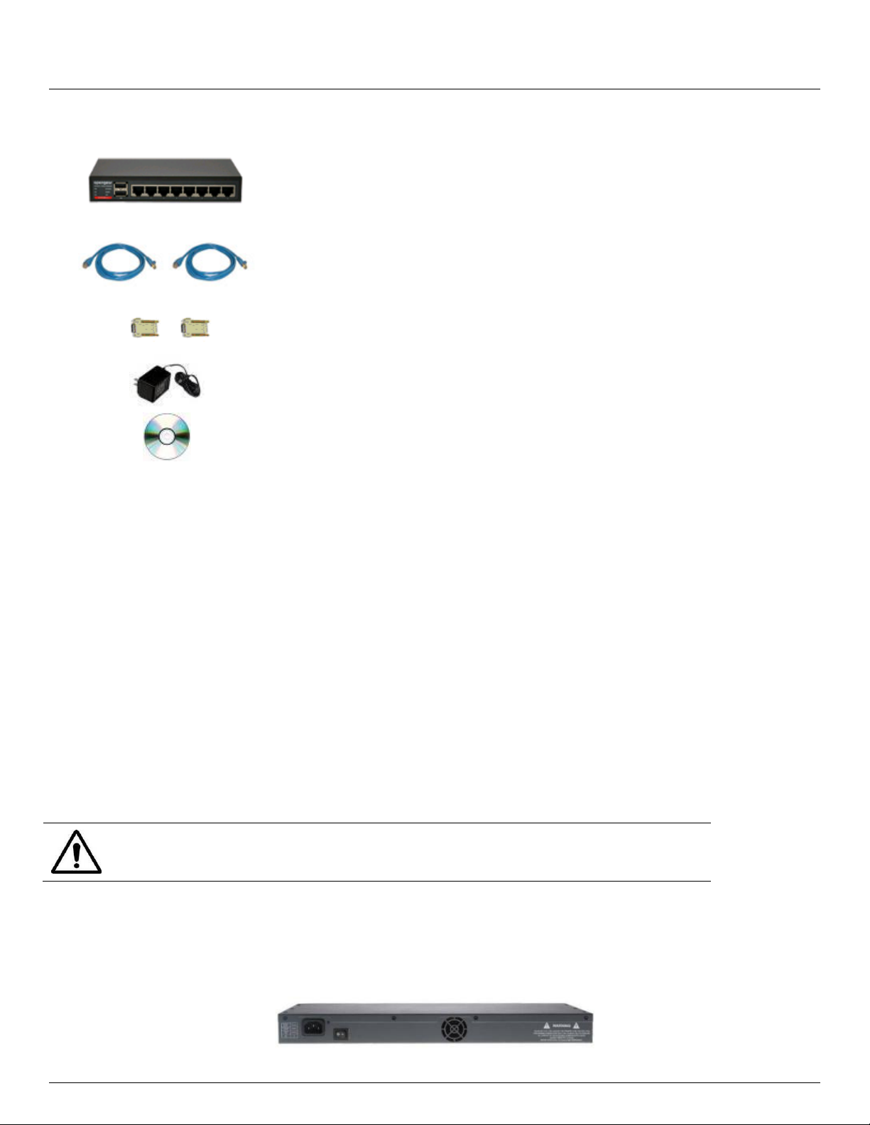
2.1.4 CM4008 kit components
Unpack your CM4008 kit and verify you have all the parts shown above, and that they all appear in good working
order
Proceed to connect your CM4008 to the network, the serial ports of the controlled servers and AC power as
shown below
2.1.5 CM4001 and SD4002 kit components
Unpack your CM4001 (or SD4002) and verify you have all the parts shown above, and that they all appear in
good working order
Proceed to connect your CM4001 (or SD4002) to the network, to the serial port of the controlled device and to
power as outlined below
Advanced Console Server & RIM Gateway User Manual 19
Page 20

Chapter 2: Installation
Part # 509068
SD4001 Serial Device Server
Part # 319018
Connector DB9F to RJ45 crossover
Part # 450026
Universal Input 12 VDC Wall mount Power Supply
Part # 539000
Quick Start Guide and CD-ROM
Part # 509054
Part # 509055
Part # 509056
Part # 509057
Part # 509058
Part # 509059
Part # 509000
Part # 509073
ACM5002 Advanced Console Server
ACM5003-M
ACM5003-W
ACM5004
ACM5004-2
ACM5004-G
ACM5004-G-I
ACM5004-2-I
Part # 440016
2 x Cable UTP Cat5 blue
Part # 3190014 and
3190015
Cisco Connector DB9F-RJ45 straight and DB9F-RJ45
cross-over
Part # 4500XX
Power Supply 12VDC 1.0A
Wall mount
Part #539000
Quick Start Guide and CD-ROM
2.1.6 SD4001 kit components
Unpack your SD4001 and verify you have all the parts shown above, and that they all appear in good working
order
Proceed to connect your SD4001 to the network, to the serial port of the controlled device and to power as
outlined below
2.1.7 ACM5000 kit components
Unpack your ACM5000 kit and verify you have all the parts shown above, and that they all appear in good
working order. The ACM5004-G has an external 3G aerial to be attached.
Proceed to connect your ACM5000 to the network, the serial ports of the controlled servers and AC power as
20 Console Server & RIM Gateway User Manual
shown below
Page 21
Part # 509110
Part # 509109
Part # 509108
Part # 509115
Part # 509107
ACM5508-2-M RIM Gateway
ACM5508-2-I RIM Gateway
ACM5504-5-G-I RIM Gateway
ACM5504-5-GV-I RIM Gateway
ACM5504-2-P RIM Gateway
Part # 440016
2 x Cable UTP Cat5 blue
Part # 3190014 and
3190015
Cisco Connector DB9F-RJ45 straight and DB9F-RJ45
cross-over
Part # 4500--
Power Supply 12VDC 1.0A
Wall mount
Part #539000
Quick Start Guide and CD-ROM
To avoid electrical shock the power cord grounding conductor must be connected to
ground
User Manual
2.1.8 ACM5500 kit components
Unpack your ACM5000 kit and verify you have all the parts shown above, and that they all appear in good
working order
The ACM5004-5-G(V)-I also has an external 3G aerial to be attached
Proceed to connect your ACM5500 to the network, serial and USB ports of the controlled devices, environmental
monitors and AC power as shown below
2.2 Power Connection
2.2.1 IM4216-34-DAC, IM4208-2-DAC, IM4216-2-DAC, IM4232-2-DAC and IM4248-2-DAC power
These standard IM42xx and IM4216-34 console servers all have dual universal AC power supplies with auto failover built
in. These power supplies each accept AC input voltage between 100 and 240 VAC with a frequency of 50 or 60 Hz and
the total power consumption per console server is less than 30W. Two IEC AC power sockets are located at the rear of
the metal case, and these IEC power inlets use conventional IEC AC power cords. Power cords for various regions are
available, although the North American power cord is provided by default. There is a warning notice printed on the back of
each unit.
2.2.2 CM4116-SAC, CM4132-SAC and CM4148-SAC power
These standard CM4116, CM4132 and CM4148 models have a built-in universal auto-switching AC power supply. This
power supply accepts AC input voltage between 100 and 240 VAC with a frequency of 50 or 60 Hz and the power
consumption is less than 20W.
Advanced Console Server & RIM Gateway User Manual 21
Page 22

Chapter 2: Installation
To avoid electrical shock the power cord grounding conductor must be connected to
ground
CM4116, CM4132 and CM4148 models have an IEC AC power socket located at the rear of the metal case. This IEC
power inlet uses a conventional IEC AC power cord, and the power cords for various regions are available. (The North
American power cord is provided by default). There is a warning notice printed on the back of each unit.
2.2.3 IM4004-5 and CM4008 power
The IM4004-5 and CM4008 are supplied with an external power supply unit. This unit accepts an AC input voltage
between 100 and 250 VAC with a frequency of 50Hz or 60Hz. The power supply has an IEC AC power socket, which
accepts a conventional IEC AC power cord. The power cord for North American is provided by default. The 5V DC
connector from the power supply plugs into the 5VDC power socket on the rear of the IM4004-5 or CM4008 chassis.
Plug in the AC power cable and the DC power cable and turn AC power On
Confirm the Power LED is lit (Note: When you have applied power to the CM4008 you will also observe the LEDs
P1 through P8 light up in sequence)
2.2.4 CM4001/ SD4002 and SD4001 power
The CM4001/ SD4002 and SD4001 models are each supplied with an external DC wall mount power supply.
A specific power supply models for each region will have been supplied (as specified by the –US, -EU, -UK –JP or –AU
extension to the part number)
The 12V DC connector from the power supply unit plugs into the DC power socket on the side of the console server
casing
Plug in the power supply AC power cable and the DC power cable
Turn on the AC power and confirm the console server Power LED (PWR) is lit.
Note: When you first apply power to the SD4002/ CM4001 you will observe the Local and Serial LEDs flashing alternately)
The CM4001/SD4002 can also be powered directly from any +9V DC to +48V DC power source by connecting the DC
power lines to the IN-GND and IN-VIN+ screw jacks.
2.2.5 ACM500x, ACM500x-2, ACM500x-M/W/I/G and ACM500x-SDC power
All the ACM5000 models are supplied with an external AC-12VDC wall mount power supply. This comes with a selection
of wall socket adapters for each geographic region (North American, Europe, UK, Japan or Australia). The 12V DC
connector from the power supply unit plugs into the 12VDC (PWR) power jack on the side of the console server casing
Plug in the power supply AC power cable and the DC power cable
Turn on the AC power and confirm the console server Power LED (PWR) is lit
22 Console Server & RIM Gateway User Manual
Page 23
The ACM5000 models can also be powered from an external +9V DC to +30V DC power
source - by connecting the DC power lines to a power plug that plugs into the 12VDC
(PWR) jack.
Similarly the ACM5000 can be powered by connecting an external 9V AC to 24V AC
power source to this jack.
The industrial ACM5004-2-I model also can be powered externally by connecting a +9 to
+30V DC power source to the DC PWR and GND connectors on the green screw
terminal block on the side of the unit.
The industrial ACM5508-2-I and ACM5504-5-G-I models also can be
powered externally by connecting a +9 to +30V DC power source to
the EXT 9-30V DC and GND connectors on the green screw terminal
block on the side of the unit.
Note
All ACM5000 models can also be ordered with the -SDC option. These units are
supplied with an external DC-DC power converter. This converter has an integrated
power cable/connector that plugs into the 12VDC (PWR) connector on the ACM5000.
The input voltage for the DC-DC converter is plus or minus 36V DC to 72V DC
Note
An external DC-DC power converter can be ordered as an accessory with any
ACM5500 RIM gateway. This converter has an integrated power cable/connector that
plugs into the 12VDC (PWR) connector on the ACM5500. The input voltage for the DC-
DC converter is plus or minus 36V DC to 72V DC
User Manual
2.2.6 ACM5508-2-M, ACM5508-2-I, ACM5504-5-G-I, ACM5504-5-GV-I and ACM5504-2-P power
All the ACM5500 models are supplied with an external AC-12VDC wall mount power supply. This comes with a selection
of wall socket adapters for each geographic region (North American, Europe, UK, Japan or Australia). The 12V DC
connector from the power supply unit plugs into the 12VDC (PWR) power jack on the side of the console server casing
Plug in the power supply AC power cable and the DC power cable
Turn on the AC power and confirm the console server Power LED (PWR) is lit
The ACM5500 models can also be powered from an external +9V DC to +30V DC power source - by connecting the DC
power lines to a power plug that plugs into the 12VDC (PWR) jack.
Similarly the ACM5500 can be powered by connecting an external 9V AC to 24V AC power source to this jack.
The ACM5504-2-P can be PoE powered using 802.3af compliant power sources.
2.2.7 IM4216-34-DDC, IM4208-2-DDC, IM4216-2-DDC, IM4232-2-DDC and IM4248-2-DDC power
The IM42xx and IM4216-34 DDC console servers all have dual DC power supplies with auto failover built in. To connect
to the DC input supply:
Strip the DC wire insulation to expose approximately 0.4 inch (10 mm) of conductor
Advanced Console Server & RIM Gateway User Manual 23
Page 24
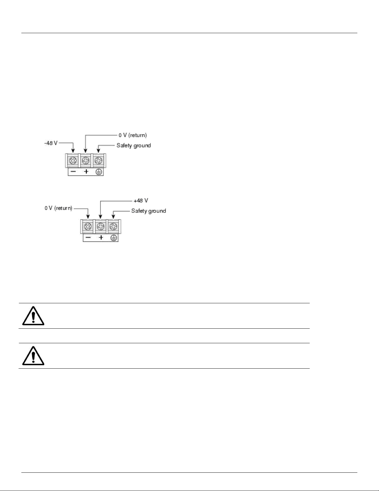
Chapter 2: Installation
The safety covers are an integral part of the DDC product. Do not operate the unit
without the safety cover installed.
Any exposed wire lead from a DC-input power source can conduct harmful levels of
electricity. So ensure that no exposed portion of the DC-input power source wire
extends from the terminal block plug and safety cover
Connect the safety ground wire to the ‘E’ safety ground terminal on the terminal block first. The DDC is floating
(w.r.t. Earth), however the safety terminal on the three way screw terminal block connects to Earth or Chassis
Ground
Connect the power wires to the appropriate terminals of the terminal block:
The ‘+’ Terminal on the four way screw terminal block should always be connect to the more positive voltage
(from 0V to +48 V)
The ‘-‘ terminal on the four way screw terminal block should connect to the more negative voltage (from -48V to
0V)
So the connections for -48 Volt DC input power are:
The connections for -48 Volt DC input power are:
Tighten the terminal screw to a torque of 8.0 ± 0.5 in-lb (0.93 ± 0.05 N-m)
Repeat the connection steps above for the second power supply
Turn on the DC power
2.3 Network Connection
The RJ45 LAN ports are located on the front panel of the rack-mount CM41xx and IM42xx console servers. The RJ45
LAN ports are located on the side of the smaller ACM5500, ACM5000, CM4001/8 and SD4001/2 units.
All physical connections are made using industry standard Cat5 cabling and connectors. Ensure you only connect the
LAN port to an Ethernet network that supports 10Base-T/100Base-T.
For the initial configuration of the console server you must connect a computer to the console server’s principal network
port. This port is labeled NETWORK (on IM4004-5), NETWORK1 (on IM4200), LAN (on ACM5500, CM4000 and
SD4000), LAN USB1 (on ACM5000).
24 Console Server & RIM Gateway User Manual
Page 25

User Manual
2.4 Serial Port Connection
Console servers all come with one to forty eight serial ports, marked SERIAL or SERIAL PORTS. These ports connect to
serially Managed Devices. Each console server also has either a dedicated Local Console (or modem) port marked
LOCAL or CONSOLE, or one or its SERIAL ports can be software configured in Local Console mode. This Local Console
port can be used for local command line access (or external serial modem out of band connection).
- All console server models except the SD4001, ACM5000 and ACM5500 have a dedicated DB9 Local Console
port. This DB9 connector is located on the front of the CM4100, IM4004-5 and IM4200 models and on the rear of
the CM4001 and CM4008.
- The ACM5002 (and ACM5003/5004) model has two (or three or four) SERIAL PORTS presented as RJ45 ports
1-4. Similarly the ACM5504 and ACM5508 models have four or eight SERIAL PORTS presented as RJ45 ports
1-8. Port 1 on all these models by default is configured in Local Console mode
- The SD4002 has two DB9 serial ports (Ports 1-2). By default Port 1 is configured in Local Console (modem)
mode. Similarly the SD4001 has one DB9 serial port and by default it is configured in Local Console (modem)
mode
Conventional Cat5 cabling with RJ45 jacks is generally used for serial connections. Opengear supplies an extensive
range of cables and adapters that may be required to connect to the more popular servers and network appliances.
These are also overviewed in Appendix D - Connectivity and Serial I/O. More detailed information is available online at
http://www.opengear.com/cabling.html
Before connecting the console port of an external device to the console server serial port, confirm that the device does
support the standard RS-232C (EIA-232).
The console servers come with one to forty eight serial connectors for the RS232 serial ports:
- The SD4001 and SD4002/CM4001 models have DB9 serial port connectors. All other models have RJ45 serial
port connectors
- The RJ45 serial ports are located on the rear panel of the IM4004-5 and CM4008; on the front face of the
ACM5000 and ACM5500; and on the front panel of the rack mount IM4216-34, CM4100 and IM4200
- The ACM5000, ACM5500 and IM4216-34 models have Cisco serial pinouts on the RJ45 connectors (refer 2.4.3
below)
- The CM4100, CM4000 and IM4004-5 models have Opengear Classic RJ45 pinout (refer 2.4.1).
- The IM4200 console servers are available with a selection of alternate RJ45 pinouts e.g. the IM4208-2, IM4216-2
and IM4248-2 console servers have three RJ45 pinout configurations available - Opengear Classic, Cisco
Straight or Cyclades/Cisco Rolled (refer 2.4.1)
These alternate pinouts need to be specified in the part number at the time of order e.g. to order an IM4248-2
dual power supply AC USA model, specify:
IM4248-2-DAC-US-X0 for a unit equipped with standard Opengear Classic RJ pinouts
IM4248-2-DAC-US-X1 for a unit equipped with Cyclades RJ pinouts (rolled cable connection)
IM4248-2-DAC-US-X2 for a unit equipped with Cisco RJ pinouts (straight through cable)
Some console server models support RS-422 and RS-485 as well as RS-232:
- The four RJ45 serial ports on the ACM5004-2-I and ACM5504-5-G-I are each RS-232/422/485 software
selectable - as are the eight RJ45 serial ports on the ACM5508-2-I
- The SD4002 has one DB9 RS-232 serial port (Port 1) and one DB9/connector block RS-232/422/485 software
selectable serial port (Port 2)
- Similarly the SD4001 has one DB9 RS-232 serial port which can be hardware selected to be RS-232 or
RS422/485
Advanced Console Server & RIM Gateway User Manual 25
Page 26

Model
Serial Port
Dedicated Console/
Modem port
#
Connectors
Pinout
RS232
RS422/485
ACM500x
2,3,4
RJ
X2 Cisco Y N
N*
ACM5004-I
4
RJ
X2 Cisco Y Y
N*
ACM550x
4,8
RJ
X2 Cisco Y N
N*
ACM550x-I
4,8
RJ
X2 Cisco Y Y
N*
IM42xx-2
8,16,32,48
RJ
X0 Classic or
X1 Avocent or
X2 Cisco
Y N Y
IM4216-34
16
RJ
X2 Cisco Y N
Y
IM4004-5
4
RJ
X0 Classic
Y N Y
CM41xx
16,48
RJ
X0 Classic
Y N Y
CM4008 8 RJ
X0 Classic
Y N Y
CM4001
1
DB9
DB9 Y N
Y
SD4001 1 DB9
DB9 Y Y
N*
SD4002 2 DB9
DB9
Y
Y(1 port)
N*
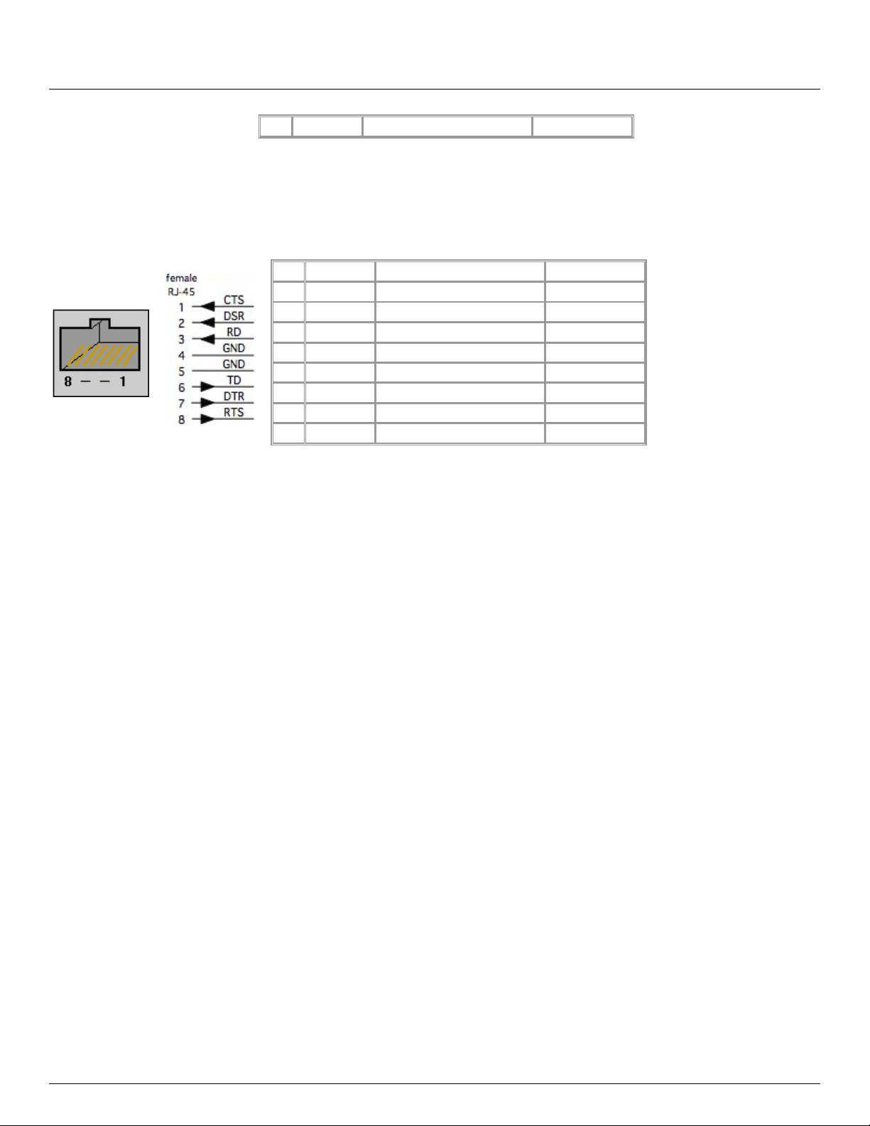
PIN
SIGNAL
DEFINITION
DIRECTION
1
RTS
Request To Send
Output
2
DSR
Data Set Ready
Input
3
DCD
Data Carrier Detect
Input
4
RXD
Receive Data
Input
5
TXD
Transmit Data
Output
6
GND
Signal Ground
NA
7
DTR
Data Terminal Ready
Output
8
CTS
Clear To Send
Input
PIN
SIGNAL
DEFINITION
DIRECTION
1
RTS
Request To Send
Output
2
DTR
Data Terminal Ready
Output
3
TXD
Transmit Data
Output
4
GND
Signal Ground
NA
5
CTS
Clear To Send
Input
6
RXD
Receive Data
Input
7
DCD
Data Carrier Detect
Input
- Refer Appendix D - Connectivity and Serial I/O for RS422/485 pinout and connection details
So in summary:
Chapter 2: Installation
*The first serial port can be reassigned to be a console/modem port
2.4.1 Opengear Classic RJ45 pinout (option –X0)
The CM4000, CM4100 and IM4004 models have the Opengear Classic RJ45 pinout shown below. The IM4200 console
servers are also available with this RJ45 pinout as an option:
2.4.2 Cisco Rolled (Cyclades) RJ45 pinout (option -X1)
The IM4200 console servers are the only products which are available with this RJ45 pinout option. This makes it easy to
replace Avocent Cyclades products, and is convenient for use with rolled RJ-45 cable:
26 Console Server & RIM Gateway User Manual
Page 27
8
DSR
Data Set Ready
Input
PIN
SIGNAL
DEFINITION
DIRECTION
1
CTS
Clear To Send
Input
2
DSR
Data Set Ready
Input
3
RXD
Receive Data
Input
4
GND
Signal Ground
NA
5
GND
Signal Ground
NA
6
TXD
Transmit Data
Output
7
DTR
Data Terminal Ready
Output
8
RTS
Request To Send
Output
User Manual
2.4.3 Cisco RJ45 pinout (option -X2)
The ACM5000, ACM5500 and IM4216-34 models have Cisco serial pinouts on its RJ45 connectors. The IM4200 console
servers are also available with this RJ45 pinout. This provides straight through RJ-45 cable to equipment such as Cisco,
Juniper, SUN, and many more:
2.5 USB Port Connection
Most console server models have external USB ports and these ports are mostly USB2.0. They can be used for:
connecting to USB consoles of Managed Devices (e.g. for managing UPS supplies)
attaching other external USB peripherals (e.g. an external USB memory stick or modem)
adding supported Sierra Wireless cellular USB modems
plugging in USB hubs to provide additional ports
Some console server models also have a USB1.1 port and this is best reserved for use with an external USB memory
stick dedicated to recovery firmware boot images/ extended log file storage etc.
The IM42xx-2-DAC-X2-G and IM42xx-2-DAC-X0-G models have one USB1.1 port on the front face and one USB 2.0
port at the rear face. This USB2.0 port uses a micro-AB USB connector so an adapter cable is also included. These
models also have 16GB flash installed internally via a USB 2.0 flash drive for improved logging.
All the other models in the IM42xx-X family (IM42xx-2-DxC-Xx models such as IM4208-2-DAC-X0, IM4248-2-DDC-X2
and IM4216-34-DAC-X2) have one USB1.1 port on the front face and two additional USB 2.0 ports at the rear face
(adjacent to modem jack). These IM42xx-X models also have an internal 16GB flash drive.
The ACM5500 and IM4004-5 models all have an internal 4GB USB flash drive as well as two unallocated external
USB2.0 ports
The ACM5000 models have two USB2.0 ports. However one or both of these may be pre-allocated internally. For
example the ACM5004-W has one internal USB committed for the 802.11 adapter, so there is only one external USB
port free. Similarly with ACM5004-F model an internal USB flash is fitted, using up one of the two USB2.0 ports
2.6 Fitting Cellular SIM and Antennas
The ACM5504-5-G-I, ACM5004-G and ACM5004-G-I each has an internal 3G cellular modem that requires at least
one (or more) SIM cards to be installed and at least one external antenna to be attached. The ACM5004-GV also
has an internal cellular modem requiring external antenna connection however the Verizon network does not
require a SIM card.
Advanced Console Server & RIM Gateway User Manual 27
Page 28

Chapter 2: Installation
You must install the SIM card before powering on the device.
For the ACM5004-G/G-I unscrew the cover plate on the side of the
insert the SIM into the SIM garage then screw the cover plate back on.
The ACM5004-5-G-I can hold two SIM cards from alternate carriers,
however only requires one SIM to operate. Unscrew the SIM card
access panel and insert the first carrier SIM card in the top SIM slot with
contacts facing downward and the notch to RHS. A second carrier SIM
can then be installed in the slot underneath the first. screw the cover
plate back on.
The IM42xx-2-DAC-X2-G and IM42xx-2-DAC-X0-G models have an internal 3G cellular modem that requires a SIM
card and external antenna.
All the other IM4200, ACM5000, ACM5500 and IM4004-5 models support an external USB cellular modem. Such
modems have internal antennas however they may benefit from an external antenna.
2.6.1 ACM5004-G/G-I and ACM5504-5-G-I SIM
The ACM5004-G/G-I and ACM5004-5-G-I models work with GSM carriers globally. Your carrier will provide you with
a SIM card for activating you data plan.
2.6.2 ACM5004-G/G-I/GV and ACM5504-5-G-I antenna
Screw the provided antenna on to have MAIN SMA antenna connector on the rear of the ACM5004-G/GI. Then place the
unit and/or aerial in a location that will ensure the best signal.
The ACM5504-5-G-I, ACM5004-G-I and current revisions of the ACM5004-G/GV all come with dual SMA antenna
connectors. The AUX connector can be used for receive diversity. This requires an external antenna (accessory Part#
569006) and cable (Part# 449041).
With the ACM5504-5-G-I and ACM5004-G-I models, the AUX connector can also be used for GPS. An external GPS
passive antenna with magnetic base, SMA connector and 2 meter cable is available (Part # 569008).
Note The ACM5004-G/G-I/GV has two cellular status LEDs. The SIM LED on top of unit should go on solid when the
ACM5004-G/G-I has been powered and a SIM card has been inserted and detected.
The WWAN LED on top of unit should go on at a fast blink once a radio connection has been established with
your cellular carrier (i.e. after an APN has been properly configured).
WWAN LED Status:
Off: In reset mode or not powered.
Slow blink: Searching for service.
Solid Green: Active service with no traffic detected.
Fast Blink: Active service with traffic (blink rate is proportional to traffic detected)
2.6.3 IM42xx-2-DAC-X2-G and IM42xx-2-DAC-X0-G
The IM42xx-2-DAC-X2-G and IM42xx-2-DAC-X0-G models have an internal 3G-GSM HSUPA/UMTS cellular modem
(and an internal 16GB flash memory and an additional USB port at the rear). They are also supplied with an external
antenna with extension cable, and a USB adapter cable.
28 Console Server & RIM Gateway User Manual
Page 29

Before powering on the console server:
Your carrier will provide you with a SIM card. Insert the SIM card
with contacts facing upward. It will lock into place
Screw the external antenna coax cable onto the MAIN screw mount
SMA connector on the rear of the console server
The AUX connector can be used either for receive diversity
(requires external antenna Part# 569006 and cable Part# 449041)
or for GPS (requires external GPS passive antenna with cable
Part# 569008).
User Manual
2.6.4n External USB cellular modems
All the IM42xx-X models support external USB GSM/HSPA or CDMA/EV-DO cellular modems from Sierra Wireless.
The USB modem attaches to one of the rear USB 2.0 ports on the IM4200-DAC-X2 via the modem’s USB adapter
cable. Similarly external USB cellular modem can be attached to the USB ports on any ACM5000 or an IM4004-5.
External modems have their own internal antennas however they generally benefit from an external antenna.
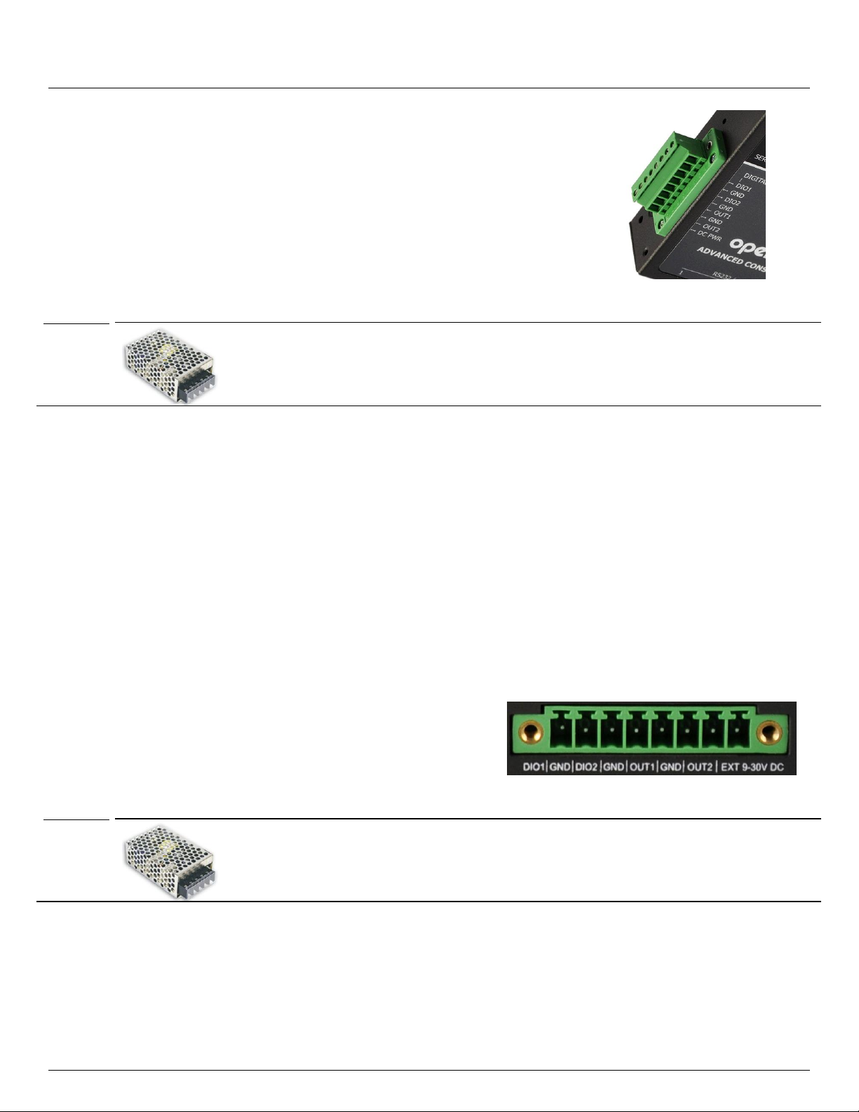
2.7 Digital I/O and Environmental Sensors
Any ACM5000 or ACM5500 model with an –I in the model number, or any ACM5000 with the –E option all ship with
an external green connector block for attaching environmental sensors and digital I/O devices.
Plug in this block and screw in any external devices.
On the ACM5508-2-I, ACM5504-5-G-I, ACM5004-2-I and ACM5004-G-I models this block can also be used for
connecting the external DC power source.
Refer Chapter 8 for further details.
Advanced Console Server & RIM Gateway User Manual 29
Page 30

Chapter 3: Initial System Configuration
SYSTEM CONFIGURATION
This chapter provides step-by-step instructions for the initial configuration of your console server, and connecting it to the
Management or Operational LAN. This involves the Administrator:
Activating the Management Console
Changing the Administrator password
Setting the IP address console server’s principal LAN port
Selecting the network services to be supported
This chapter also discusses the communications software tools that the Administrator may use in accessing the console
server, and the configuration of the additional LAN ports.
3.1 Management Console Connection
Your console server comes configured with a default IP Address 192.168.0.1 Subnet Mask 255.255.255.0
Directly connect a Computer to the console server
Note For initial configuration it is recommended that the console server be connected directly to a single Computer.
However, if you choose to connect your LAN before completing the initial setup steps, it is important that:
you ensure there are no other devices on the LAN with an address of 192.168.0.1
the console server and the computer are on the same LAN segment, with no interposed router appliances
3.1.1 Connected computer set up
To configure the console server with a browser, the connected PC/workstation should have an IP address in the same
range as the console server (for example, 192.168.0.100):
To configure the IP Address of your Linux or Unix computer simply run ifconfig
For Windows PCs (Win9x/Me/2000/XP/Vista/7/NT):
Click Start -> (Settings ->) Control Panel and double click Network Connections (for 95/98/Me, double
click Network).
Right click on Local Area Connection and select Properties.
Select Internet Protocol (TCP/IP) and click Properties.
Select Use the following IP address and enter the following details:
o IP address: 192.168.0.100
o Subnet mask: 255.255.255.0
If you want to retain your existing IP settings for this network connection, click Advanced and Add the above
as a secondary IP connection.
If it is not convenient to change your computer network address, you can use the ARP-Ping command to reset the
console server IP address. To do this from a Windows PC:
Click Start -> Run (or select All Programs then Accessories then Run).
Type cmd and click OK to bring up the command line.
Type arp –d to flush the ARP cache.
Type arp –a to view the current ARP cache (this should be empty).
30 Console Server & RIM Gateway User Manual
Page 31

User Manual
Now add a static entry to the ARP table and ping the console server to assign the IP address to the console
server. In the example below, a console server has a MAC Address 00:13:C6:00:02:0F (designated on the label
on the bottom of the unit) and we are setting its IP address to 192.168.100.23. Also the computer issuing the arp
command must be on the same network segment as the console server (that is, have an IP address of
192.168.100.xxx)
Type arp -s 192.168.100.23 00-13-C6-00-02-0F (Note for UNIX the syntax is: arp -s 192.168.100.23
00:13:C6:00:02:0F).
Type ping -t 192.18.100.23 to start a continuous ping to the new IP Address.
Turn on the console server and wait for it to configure itself with the new IP address. It will start replying to the
ping at this point.
Type arp –d to flush the ARP cache again.
3.1.2 Browser connection
Activate your preferred browser on the connected PC/ workstation and enter https://192.168.0.1 The
Management Console supports all current versions of the popular browsers (Internet Explorer, Mozilla Firefox,
Google Chrome, Apple Safari and more)
You will be prompted to log in. Enter the default administration username and administration password
(Username: root Password: default)
Note Console servers are factory configured with HTTPS access enabled and HTTP access disabled.
Advanced Console Server & RIM Gateway User Manual 31
Page 32

Chapter 3: Initial System Configuration
A Welcome screen, which lists initial installation configuration steps, will be displayed. These steps are:
Change default administration password (System/Administration page. Refer Chapter 3.2)
Configure the local network settings (System/IP page. Refer Chapter 3.3)
To configure console server features:
Configure serial ports settings (Serial & Network/Serial Port page. Refer Chapter 4)
Configure user port access (Serial & Network/Users page. Refer Chapter 4)
If your system has a cellular modem you will also be given the steps to configure cellular router features:
Configure the cellular modem connection (System/Dial page. Refer Chapter 5)
Allow forwarding to the cellular destination network (System/Firewall page. Refer Chapter 5)
Enable IP masquerading for cellular connection (System/Firewall page. Refer Chapter 5)
After completing each of the above steps, you can return to the configuration list by clicking the Opengear logo in the top
left corner of the screen.
Note If you are not able to connect to the Management Console at 192.168.0.1 or if the default Username / Password
were not accepted then reset your console server (refer Chapter 10)
3.2 Administrator Password
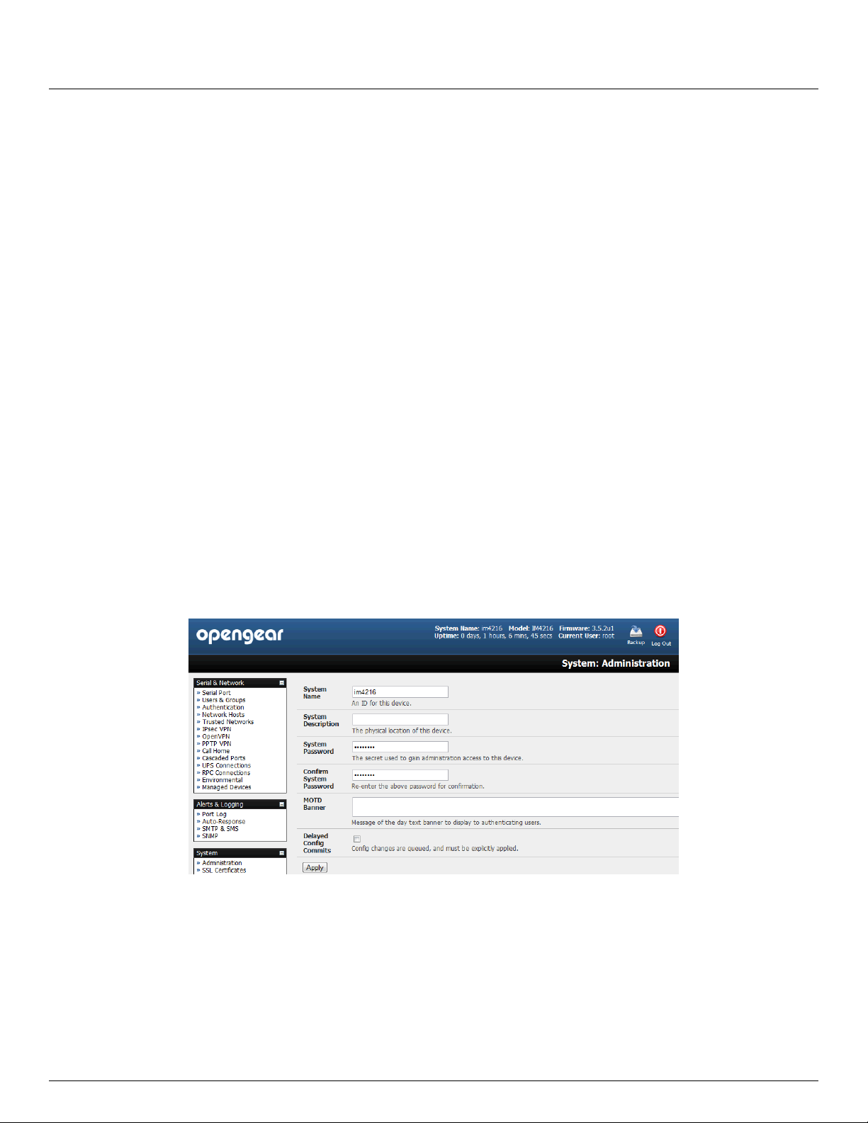
For security reasons, only the administration user named root can initially log into your console server. So only those
people who know the root password can access and reconfigure the console server itself.
The corollary is that anyone who correctly guesses the root password could gain access (and the default root password is
default). So it is essential that you enter and confirm a new password before giving the console server any access to, or
control of, your computers and network appliances.
32 Console Server & RIM Gateway User Manual
Page 33

User Manual
Select System: Administration
Enter a new System Password then re-enter it in Confirm System Password. This is the new password for
root, the main administrative user account, so it is important that you choose a complex password, and keep it
safe
At this stage you may also wish to enter a System Name and System Description for the console server to give
it a unique ID and make it simple to identify
Note The System Name can contain from 1 to 64 alphanumeric characters (however you can also use the special
characters "-" "_" and ".”). There are no restrictions on the characters that can be used in the System Description
or the System Password (which each can contain up to 254 characters). However only the first eight Password
characters are used to make the password hash.
The MOTD Banner can be used to display a “message of the day” text to authenticating users when the ssh, ftp
or web access the console server
Click Apply. As you have changed the password you will be prompted to log in again. This time use the new
password
Note If you are not confident your console server has been supplied with the current release of firmware, you can
upgrade. Refer Upgrade Firmware - Chapter 10
3.2.1 Set up new administrator
It is also recommended that you set up a new Administrator user as soon as convenient and log-in as this new user for all
ongoing administration functions (rather than root).
This Administrator can be configured in the admin group with full access privileges through the Serial & Network: Users
& Groups menu (refer Chapter 4 for details)
Advanced Console Server & RIM Gateway User Manual 33
Page 34

Chapter 3: Initial System Configuration
3.3 Network IP Address
The next step is to enter an IP address for the principal Ethernet (LAN/Network/Network1) port on the console server; or
enable its DHCP client so that it automatically obtains an IP address from a DHCP server on the network it is to be
connected to.
On the System: IP menu select the Network Interface page then check DHCP or Static for the Configuration
Method
If you selected Static you must manually enter the new IP Address, Subnet Mask, Gateway and DNS server
details. This selection automatically disables the DHCP client
If you selected DHCP the console server will look for configuration details from a DHCP server. This selection
automatically disables any static address. The console server MAC address can be found on a label on the base
plate
34 Console Server & RIM Gateway User Manual
Page 35

User Manual
Note In its factory default state (with no Configuration Method selected) the console server has its DHCP client
enabled, so it automatically accepts any network IP address assigned by a DHCP server on your network. In this
initial state, the console server will then respond to both its Static address (192.168.0.1) and its newly assigned
DHCP address
You may also enter a secondary address or comma-separated list of addresses in CIDR notation,
e.g. 192.168.1.1/24 as an IP Alias
By default the console server LAN port auto detects the Ethernet connection speed. However you can use the
Media menu to lock the Ethernet to 10 Mb/s or 100Mb/s and to Full Duplex (FD) or Half Duplex (HD)
Note If you have changed the console server IP address, you may need to reconfigure your computer so it has an IP
address that is in the same network range as this new address (as detailed in an earlier note in this chapter)
Click Apply
You will need to reconnect the browser on the computer that is connected to the console server by entering
http://new IP address
3.3.1 IPv6 configuration
By default, the console server Ethernet interfaces support IPv4; however, they can also be configured for IPv6 operation:
On the System: IP menu select General Settings page and check Enable IPv6
You will then need to configure the IPv6 parameters on each interface page
3.3.2 Dynamic DNS (DDNS) configuration
With Dynamic DNS (DDNS) an advanced console server whose IP address is dynamically assigned (and that may
change from time to time) can be located using a fixed host or domain name. The ACM5500, ACM5000, IM4004-5 and
IM4200 family of advanced console servers (with Firmware 3.0.2 and later) support DDNS.
The first step in enabling DDNS is to create an account with the supported DDNS service provider of your choice.
Advanced Console Server & RIM Gateway User Manual 35
Page 36

Chapter 3: Initial System Configuration
Supported DDNS providers include:
- DyNS www.dyns.cx
- dyndns.org www.dyndns.org
- GNUDip gnudip.cheapnet.net
- ODS www.ods.org
- TZO www.tzo.com
- 3322.org (Chinese provider) www.3322.org
Upon registering with the DDNS service provider, you will select a username and password, as well as a
hostname that you will use as the DNS name (to allow external access to your machine using a URL).
The Dynamic DNS service providers allow the user to choose a hostname URL and set an initial IP address to
correspond to that hostname URL. Many Dynamic DNS providers offer a selection of URL hostnames available
for free use with their service. However, with a paid plan, any URL hostname (including your own registered
domain name) can be used.
You can now enable and configure DDNS on any of the Ethernet or cellular network connections on the console server
(by default DDNS is disabled on all ports):
Select the DDNS service provider from the drop down Dynamic DNS list on the System:IP or System:Dial menu
In DDNS Hostname enter the fully qualified DNS hostname for your console server e.g. your-
hostname.dyndns.org
Enter the DDNS Username and DDNS Password for the DDNS service provider account
Specify the Maximum interval between updates - in days. A DDNS update will be sent even if the address has
not changed
Specify the Minimum interval between checks for changed addresses - in seconds. Updates will still only be
sent if the address has changed
Specify the Maximum attempts per update i.e. the number of times to attempt an update before giving up
(defaults to 3)
3.4 System Firewall - Service Access
Service Access specifies which access protocols/services can be used to access the console server (and connected
serial ports and managed devices). The Administrator can access and configure the console server (and connected
36 Console Server & RIM Gateway User Manual
Page 37

User Manual
devices) using a range of access protocols/services – and for each such access, the particular service must be running
with access through the firewall enabled.
By default HTTP, HTTPS, Telnet and SSH services are running, and these services are enabled on all network interfaces.
However, again by default, only HTTPS and SSH access to the console server is enabled, while HTTP and Telnet access
is disabled.
For other services, such as SNMP/Nagios NRPE/NUT, the service must first be started on the relevant network interface
using Port /Firewall Rules (refer Chapter 5). Then the Services Access can be set to allow or block access.
To change the access settings:
Select the Service Access tab on the System: Firewall page. This will displays the services currently enabled
for the console server’s network interfaces. Depending on the particular console server model the interfaces
displayed may include :
Network interface (for the principal Ethernet connection)
Dial out (V90 and cellular modem)
Dial in (internal or external V90 modem)
Wi-Fi (802.11 wireless)
OoB Failover (second Ethernet connections)
VPN (IPSec or Open VPN connection over any network interface)
Check/uncheck for each network which service access is to be enabled /disabled
In the example shown below local administrators on local Network Interface LAN have HTTP and Telnet access to the
console server (and attached serial consoles) while remote administrators using Dial In only can access the Nagios/NUT
/SNMP status.
The Services Access settings specify which services the Administrator can use over which network interface to access the
console server. It also nominates the enabled services that the Administrator and the User can use to connect through the
console server to attached serial and network connected devices.
The following general service access options can be specified:
HTTPS This ensures the Administrator has secure browser access to all the Management Console menus on
the console server. It also allows appropriately configured Users secure browser access to selected
Manage menus. For information on certificate and user client software configuration refer Chapter 9 -
Authentication. By default HTTPS is enabled, and it is recommended that only HTTPS access be used
if the console server is to be managed over any public network (e.g. the Internet).
Advanced Console Server & RIM Gateway User Manual 37
Page 38

Chapter 3: Initial System Configuration
HTTP The HTTP service allows the Administrator basic browser access to the Management Console. It is
recommended the HTTP service be disabled if the console server is to be remotely accessed over the
Internet.
Telnet This gives the Administrator telnet access to the system command line shell (Linux commands). While
this may be suitable for a local direct connection over a management LAN, it is recommended this
service be disabled if the console server is to be remotely administered. This service may also be
useful for local Administrator and the User access to selected serial consoles
SSH This service provides secure SSH access. It is recommended you choose SSH as the protocol where
the Administrator connects to the console server over the Internet or any other public network. This will
provide authenticated communications between the SSH client program on the remote computer and
the SSH sever in the console server. For more information on SSH configuration refer Chapter 9 -
Authentication.
There are also a number of related service options that can be configured at this stage:
SNMP This will enable netsnmp in the console server, which will keep a remote log of all posted information.
SNMP is disabled by default. To modify the default SNMP settings, the Administrator must make the
edits at the command line as described in Chapter 15 – Advanced Configuration
TFTP/FTP If a USB flash card or internal flash is detected on an ACM5000, ACM5500, IM4200 or IM4004-5
advanced console server, then enabling this service will set up default tftp and ftp server on the USB
flash. These servers are used to store config files, maintain access and transaction logs etc. Files
transferred using tftp and ftp will be stored under /var/tmp/usbdisk/tftpboot
Ping This allows the console server to respond to incoming ICMP echo requests. Ping is enabled by
default, however for security reasons this service should generally be disabled post initial configuration
Nagios Access to the Nagios NRPE monitoring daemons
NUT Access to the NUT UPS management daemons
And there are some serial port access parameters that can be configured on this menu:
Base The console server uses specific default ranges for the TCP/IP ports for the various access services
that Users and Administrators can use to access devices attached to serial ports (as covered in
Chapter 4 – Configuring Serial Ports). The Administrator can also set alternate ranges for these
services, and these secondary ports will then be used in addition to the defaults.
The default TCP/IP base port address for telnet access is 2000, and the range for telnet is IP Address:
Port (2000 + serial port #) i.e. 2001 – 2048. So if the Administrator were to set 8000 as a secondary
base for telnet then serial port #2 on the console server can be telnet accessed at IP Address:2002
and at IP Address:8002. The default base for SSH is 3000; for Raw TCP is 4000; and for RFC2217 it
is 5000
RAW/Direct You can also specify that serial port devices can be accessed from nominated network interfaces
using Raw TCP, direct Telnet/SSH, unauthenticated Telnet services etc
Click Apply. As you apply your services selections, the screen will be updated with a confirmation message:
Message Changes to configuration succeeded
38 Console Server & RIM Gateway User Manual
Page 39

User Manual
3.5 Communications Software
You have configured access protocols for the Administrator client to use when connecting to the console server. User
clients (who you may set up later) will also use these protocols when accessing console server serial attached devices
and network attached hosts. So you will need to have appropriate communications software tools set up on the
Administrator (and User) client’s computer. Opengear provides the SDT Connector as the recommended client software
tool, however other generic tools such as PuTTY and SSHTerm may be used, and these are all described below.
3.5.1 SDT Connector
Opengear recommends using the SDT Connector communications software tool for all communications with Console
servers, to ensure these communications are secure. Each console server is supplied with an unlimited number of SDT
Connector licenses to use with that console server.
Advanced Console Server & RIM Gateway User Manual 39
Page 40

Chapter 3: Initial System Configuration
To use PuTTY for an SSH terminal session from
a Windows client, you enter the console server’s
IP address as the ‘Host Name (or IP address)’
To access the console server command line you
select ‘SSH’ as the protocol, and use the default
IP Port 22
Click ‘Open’ and you will be presented with the
console server login prompt. (You may also
receive a ‘Security Alert’ that the host’s key is
not cached, you will need to choose ‘yes’ to
continue.)
Using the Telnet protocol is similarly simple - but
you use the default port 23
SDT Connector is a light weight tool that enables Users and Administrators to securely access the Console server, and
the various computers, network devices and appliances that may be serially or network connected to the console server.
SDT Connector is a Java client program that couples the trusted SSH tunneling protocol with popular access tools such
as Telnet, SSH, HTTP, HTTPS, VNC, RDP to provide point-and-click secure remote management access to all the
systems and devices being managed.
Information on using SDT Connector for browser access to the console server’s Management Console, Telnet/SSH
access to the console server command line, and TCP/UDP connecting to hosts that are network connected to the console
server can be found in Chapter 6 - Secure Tunneling
SDT Connector can be installed on Windows 2000, XP, 2003, 7, Vista PCs and on most Linux, UNIX and Solaris.
3.5.2 PuTTY
Communications packages like PuTTY can be also used to connect to the Console server command line (and to connect
serially attached devices as covered in Chapter 4). PuTTY is a freeware implementation of Telnet and SSH for Win32 and
UNIX platforms. It runs as an executable application without needing to be installed onto your system. PuTTY (the Telnet
and SSH client itself) can be downloaded at http://www.tucows.com/preview/195286.html
40 Console Server & RIM Gateway User Manual
Page 41

A new dialog box will appear for your ‘Connection Profile’
where you can type in the host name or IP address (for the
console server unit) and the TCP port that the SSH session
will use (port 22). Then type in your username and choose
password authentication and click connect.
You may receive a message about the host key fingerprint,
and you will need to select ‘yes’ or ‘always’ to continue.
The next step is password authentication and you will be
prompted for your username and password from the remote
system. You will then be logged on to the console server
User Manual
3.5.3 SSHTerm
Another common communications package that may be useful is SSHTerm, an open source package that can be
downloaded from http://sourceforge.net/projects/sshtools:
To use SSHTerm for an SSH terminal session from a Windows Client you simply Select the ‘File’ option and click on
‘New Connection’
3.6 Management Network Configuration
The IM4200, IM4004-5, ACM5500 and ACM5004-2 console servers have additional network ports that can be configured
to provide management LAN access and/or failover or out-of-band access.
3.6.1 Enable the Management LAN
The IM4200 family, ACM5508-2-I/M and ACM5004-2 console servers can be configured so the second Ethernet port
provides a management LAN gateway. The gateway has firewall, router and DHCP server features. However you need to
connect an external LAN switch to Network/LAN 2 to attach hosts to this management LAN:
Note The second Ethernet port (Network/LAN2) on the IM4200, ACM5508-2-I/M and ACM5004-2 can be configured as
Advanced Console Server & RIM Gateway User Manual 41
either a Management LAN gateway port or it can be configured as an OoB/Failover port. It cannot be both. So
ensure you did not allocate Network/LAN 2 as the Failover Interface when you configured the principal Network
connection on the System: IP menu.
Page 42

Chapter 3: Initial System Configuration
The ACM5504-5-G-I, IM4216-34 and IM4004-5 console server models have an integrated four or thirty-two port
management LAN switches (with firewall, router, DHCP server and switch functions).
The IM4216-34 is normally configured to have an active 32 port Management LAN (Ethernet 1-32) switch plus
have Network 2 configured for OoB or Failover
The IM4004-5 and AM5504-5-G-I similarly is normally be configured with an active Management LAN. This can
be a 4 port (ETH1-4) Management LAN switch, or a 3 port (ETH2-4) switch with ETH 1 configured for
OoB/Failover
The above Management LAN features are all disabled by default. To configure the Management LAN gateway:
Select the Management LAN Interface page on the System: IP menu and uncheck Disable
Configure the IP Address and Subnet Mask for the Management LAN (but leave the DNS fields blank)
Click Apply
The management gateway function is now enabled with default firewall and router rules. By default these rules are
configured so the Management LAN can only be accessible by SSH port forwarding. This ensures the remote and local
42 Console Server & RIM Gateway User Manual
Page 43

User Manual
connections to Managed Devices on the Management LAN are secure. The LAN ports can also be configured in bridged
or bonded mode (as described later in this chapter) or they can be manually configured from the command line.
3.6.2 Configure the DHCP server
The IM4200 family, ACM5508-2-I/M, ACM5504-5-G-I, IM4004-5 and ACM5004-2 console servers also host a DHCP
server which by default is disabled. The DHCP server enables the automatic distribution of IP addresses to devices on
the Management LAN that are running DHCP clients. To enable the DHCP server:
On the System: IP menu select the Management LAN page and click the Disabled label in the DHCP Server
field (or go to the System: DHCP Server menu and check Enable DHCP Server )
Enter the Gateway address that is to be issued to the DHCP clients. If this field is left blank, the console server’s
IP address will be used
Enter the Primary DNS and Secondary DNS address to issue the DHCP clients. Again if this field is left blank,
console server’s IP address is used, so leave this field blank for automatic DNS server assignment
Optionally enter a Domain Name suffix to issue DHCP clients
Enter the Default Lease time and Maximum Lease time in seconds. The lease time is the time that a
dynamically assigned IP address is valid before the client must request it again
Click Apply
The DHCP server will sequentially issue IP addresses from a specified address pool(s):
Click Add in the Dynamic Address Allocation Pools field
Enter the DHCP Pool Start Address and End Address and click Apply
Advanced Console Server & RIM Gateway User Manual 43
Page 44

Chapter 3: Initial System Configuration
The DHCP server also supports pre-assigning IP addresses to be allocated only to specific MAC addresses and reserving
IP addresses to be used by connected hosts with fixed IP addresses. To reserve an IP addresses for a particular host:
Click Add in the Reserved Addresses field
Enter the Hostname, the Hardware Address (MAC) and the Statically Reserved IP address for the DHCP client
and click Apply
When DHCP has initially allocated hosts addresses it is recommended to copy these into the pre-assigned list so the
same IP address will be reallocated in the event of a reboot.
3.6.3 Select Failover or broadband OoB
The IM4200 family, ACM5508-2-I/M, ACM5504-5-G-I, IM4004-5 and ACM5004-2 console servers provide a failover option
so in the event of a problem using the main LAN connection for accessing the console server; an alternate access path is
used.
By default the failover is not enabled. To enable:
Select the Network page on the System: IP menu
Now select the Failover Interface to be used in the event of an outage on the main network. This can be:
o an alternate broadband Ethernet connection (which would be the Network/LAN2 port on IM4200 family
and ACM5004-2 or ETH 1 on the IM4004-5) or
o the IM4200 family internal modem or
o an external serial modem/ISDN device connected to the IM42xx Console port (for out-dialing to an ISP or
the remote management office)
44 Console Server & RIM Gateway User Manual
Page 45

User Manual
Click Apply. You have selected the failover method however it is not active until you have specified the external
sites to be probed to trigger failover, and set up the failover ports themselves. This is covered in Chapter 5.
Note The ACM5504-5-G-I, IM4004-5 and IM4216-34 can be configured with an active Management LAN/gateway and
with one of the switched Ethernet ports configured for OoB/Failover (ETH 1 on the ACM5504-5-G-I and IM4004-5
or NETOWRK 2 on the IM4216-34). However with the other IM4200, ACM5508-2 and ACM5004-2 models, the
second Ethernet port can be configured as either a gateway port or as an OoB/Failover port, but not both. So
ensure you did not enable the Management LAN function on Network/LAN 2
3.6.4 Aggregating the network ports
By default the console server's Management LAN network ports can only be accessed using SSH tunneling /port
forwarding or by establishing an IPsec VPN tunnel to the console server.
However all the wired network ports on the console servers can be aggregated by being bridged or bonded.
By default Interface Aggregation is Disabled on the System: IP General Settings menu
Select Bridge Interfaces or Bond Interfaces
o When bridging is enabled, network traffic is forwarded across all Ethernet ports with no firewall
restrictions. All the Ethernet ports are all transparently connected at the data link layer (layer 2) so they do
retain their unique MAC addresses
o With bonding he network traffic is carried between the ports but they present with one MAC address
o Both modes remove all the Management LAN Interface and Out-of-Band/Failover Interface functions
and disable the DHCP Server
Advanced Console Server & RIM Gateway User Manual 45
Page 46

Chapter 3: Initial System Configuration
In aggregation mode all the Ethernet ports are configured collectively using the Network Interface menu
3.6.5 Wireless LAN
Some console server models support 802.11 wireless LAN connections.
- The ACM5003-W has an internal 802.11g wireless client LAN adapter
- The other ACM5000 models and IM4004-5 models can be fitted externally with a Opengear WUBR-101 802.11g
USB dongle
To configure the wireless LAN connection LAN card you must first install the USB dongle in the console server.
The wireless device will then be auto-detected on power up and you will be presented with a Wireless LAN
Interface menu in the System: IP menu
The wireless LAN is deactivated by default so to activate it first uncheck Disable
46 Console Server & RIM Gateway User Manual
Page 47

User Manual
To configure the IP settings of the wireless LAN:
Select DHCP or Static for the Configuration Method
o If you selected Static then manually enter the new IP Address, Subnet Mask, Gateway and DNS
server details. This selection automatically disables the DHCP client
o If you selected DHCP the console server will look for configuration details from a DHCP server on
your management LAN. This selection automatically disables any static address. The console server
MAC address can be found on a label on the base plate
The wireless LAN when enabled will operate as the main network connection to the console server so failover is
available (though it not enabled by default). Use Failover Interface to select the device to failover to in case of
wireless outage and specify Probe Addresses of the peers to probed for connectivity detection
Configure the Wireless Client to select the local wireless network which will serve as the main network connection
to the console server.
o Enter the appropriate SSID (Set Service Identifier) of the wireless access point to connect to
Advanced Console Server & RIM Gateway User Manual 47
Page 48

Chapter 3: Initial System Configuration
o Select the Wireless Network Type where Infrastructure is used to connect to an access point and Ad-
hoc to connect directly to a computer
o Select the Wireless Security mode of the wireless network (WEP, WPA etc) and enter the required Key/
Authentication/ Encryption settings
Note: The Wireless screen in Status: Statistics will display all the locally accessible wireless LANs (with SSID and
Encryption/Authentication settings). You can also use this screen to confirm you have successfully connected to the
selected access point - refer Chapter 12
3.6.6 Static routes
Firmware 3.4 and later support static routes which provide a very quick way to route data from one subnet to different
subnet. So you can hard code a path that specifies to the console server/router to get to a certain subnet by using a
certain path. This may be useful for remotely accessing various subnets at a remote site when being accessed using the
cellular OoB connection.
To add to the static route to the route table of the system:
Select the Route Settings tab on the System: IP General Settings menu
Enter a meaningful Route Name for the route
In the Destination Network/Host field enter the IP address of the destination network/host that the route
provides access to
Enter a value in the Destination netmask field that identifies the destination network or host. Any number
between 0 and 32. A subnet mask of 32 identifies a host route.
48 Console Server & RIM Gateway User Manual
Page 49

User Manual
Enter Route Gateway with the IP address of a router that will route packets to the destination network
Enter a value in the Metric field that represents the metric of this connection. This generally only has to be set if
two or more routes conflict or have overlapping targets. Any number equal to or greater than 0
Click Apply
Advanced Console Server & RIM Gateway User Manual 49
Page 50

Chapter 4: Serial Port, Device and User Configuration
SERIAL PORT, HOST, DEVICE & USER CONFIGURATION
The Opengear console server enables access and control of serially-attached devices and network-attached devices
(hosts). The Administrator must configure access privileges for each of these devices, and specify the services that can
be used to control the devices. The Administrator can also set up new users and specify each user’s individual access and
control privileges.
This chapter covers each of the steps in configuring network connected and serially attached devices:
Serial Ports – setting up the protocols to be used in accessing serially-connected devices
Users & Groups – setting up users and defining the access permissions for each of these users
Authentication – this is covered in more detail in Chapter 9
Network Hosts – configuring access to local network connected computers or appliances (hosts)
Configuring Trusted Networks - nominate specific IP addresses that trusted users access from
Cascading and Redirection of Serial Console Ports
Connecting to Power (UPS PDU and IPMI) and Environmental Monitoring (EMD) devices
Serial Port Redirection – using the PortShare windows and Linux clients
Managed Devices - presents a consolidated view of all the connections
IPSec – enabling VPN connection
OpenVPN
PPTP
4.1 Configure Serial Ports
The first step in configuring a serial port is to set the Common Settings such as the protocols and the RS232 parameters
that are to be used for the data connection to that port (e.g. baud rate).
Then you select what mode the port is to operate in. Each port can be set to support one of five operating modes:
i. Console Server mode is the default and this enables general access to serial console port on the serially attached
devices
ii. Device mode sets the serial port up to communicate with an intelligent serial controlled PDU, UPS or
Environmental Monitor Devices (EMD)
iii. SDT mode enables graphical console access (with RDP, VNC, HTTPS etc) to hosts that are serially connected
iv. Terminal Server mode sets the serial port to await an incoming terminal login session
50 Console Server & RIM Gateway User Manual
Page 51

User Manual
v. Serial Bridge mode enables the transparent interconnection of two serial port devices over a network
Select Serial & Network: Serial Port and you will see details of the serial ports that are currently set up
By default each serial port is set in Console Server mode. For the port to be reconfigured click Edit
When you have reconfigured the common settings (Chapter 4.1.1) and the mode (Chapters 4.1.2 - 4.1.6) for each
port, you set up any remote syslog (Chapter 4.1.7), then click Apply
Note If you wish to set the same protocol options for multiple serial ports at once click Edit Multiple Ports and select
which ports you wish to configure as a group
If the console server has been configured with distributed Nagios monitoring enabled then you will also be
presented with Nagios Settings options to enable nominated services on the Host to be monitored (refer
Chapter 10 – Nagios Integration)
4.1.1 Common Settings
There are a number of common settings that can be set for each serial port. These are independent of the mode in which
the port is being used. These serial port parameters must be set so they match the serial port parameters on the device
you attach to that port:
Specify a label for the port
Select the appropriate Baud Rate, Parity, Data Bits, Stop Bits and Flow Control for each port
Advanced Console Server & RIM Gateway User Manual 51
Page 52

Chapter 4: Serial Port, Device and User Configuration
Note The Signaling Protocol menu item only presents in ports with RS422/485 options (i.e. Port 1 on SD4002 and
SD4001, and all ports on ACM5004-2-I, ACM5508-2-I and ACM5504-5-G-I). The options available are RS232,
RS422, RS485 and RS485 Echo mode
Before proceeding with further serial port configuration, you should connect the ports to the serial devices they will
be controlling, and ensure they have matching settings
Note The serial ports are all set at the factory to RS-232 9600 baud, no parity, 8 data bits, 1 stop bit and Console
Server Mode. The baud rate can be changed to 2400 – 230400 baud using the management console. Lower
baud rates (50, 75, 110, 134, 150, 200, 300, 600, 1200, 1800 baud) can be configured from the command line.
Refer Chapter 14 – Basic Configuration (Linux Commands)
4.1.2 Console Server Mode
Select Console Server Mode to enable remote management access to the serial console that is attached to this
serial port:
Logging Level This specifies the level of information to be logged and monitored (refer Chapter 7 - Alerts and Logging)
Telnet When the Telnet service is enabled on the console server, a Telnet client on a User’s or Administrator’s computer
can connect to a serial device attached to this serial port on the console server. The Telnet communications are
unencrypted so this protocol is generally recommended only for local or VPN tunneled connections.
With Win2000/XP/NT you can run telnet from the command prompt (cmd.exe). Windows 7 and Vista come with a
Telnet client but it is not enabled by default. You can install it by following the simple steps below.
o
Click the
on or off
provide confirmation.
o
In the
Windows Features
button , click
Start
. If you are prompted for an administrator password or confirmation, type the password or
Control Panel
dialog box, select the
, click
Programs
Telnet Client
, and then click
check box.
Turn Windows features
52 Console Server & RIM Gateway User Manual
Page 53

User Manual
o
Click OK. The installation might take several minutes.
If the remote communications are being tunneled with SDT Connector, then Telnet can be used for securely
accessing these attached devices (refer Note below).
Note In Console Server mode, Users and Administrators can use SDT Connector to set up secure Telnet connections
that are SSH tunneled from their client computers to the serial port on the console server. SDT Connector can be
installed on Windows 7, 2000, XP, 2003, Vista PCs and on most Linux platforms and it enables secure Telnet
connections to be selected with a simple point-and-click.
To use SDT Connector to access consoles on the console server serial ports, you configure SDT Connector with
the console server as a gateway, then as a host, and you enable Telnet service on Port (2000 + serial port #) i.e.
2001–2048. Refer Chapter 6 for more details on using SDT Connector for Telnet and SSH access to devices that
are attached to the console server serial ports.
You can also use standard communications packages like PuTTY to set a direct Telnet (or SSH) connection to the serial
ports (refer Note below):
Note PuTTY also supports Telnet (and SSH) and the procedure to set up a Telnet session is simple. Enter the console
server’s IP address as the ‘Host Name (or IP address)’. Select ‘Telnet’ as the protocol and set the ‘TCP port’ to
2000 plus the physical serial port number (i.e. 2001 to 2048).
Click the ‘Open’ button. You may then receive a ‘Security Alert’ that the host’s key is not cached, you will need to
choose ‘yes’ to continue. You will then be presented with the login prompt of the remote system connected to the
serial port chosen on the console server. You can login as normal and use the host serial console screen.
Advanced Console Server & RIM Gateway User Manual 53
Page 54

Chapter 4: Serial Port, Device and User Configuration
PuTTY can be downloaded at http://www.tucows.com/preview/195286.html
Note In Console Server mode, when you connect through to a serial port you connect via pmshell. To will generate a
BREAK on the serial port you need to type the character sequence '~b' (and if you're doing this over SSH you'll
need to type "~~b")
SSH It is recommended that you use SSH as the protocol where the User or Administrator connects to the console
server (or connects through the console server to the attached serial consoles) over the Internet or any other
public network. This will provide authenticated SSH communications between the SSH client program on the
remote user’s computer and the console server, so the user’s communication with the serial device attached to
the console server is secure
For SSH access to the consoles on devices attached to the console server serial ports, you can use SDT
Connector. You configure SDT Connector with the console server as a gateway, then as a host, and you
enable SSH service on Port (3000 + serial port #) i.e. 3001-3048. Chapter 6 - Secure Tunneling has more
information on using SDT Connector for SSH access to devices that are attached to the console server serial
ports.
Also you can use common communications packages, like PuTTY or SSHTerm to SSH connect directly to port
address IP Address _ Port (3000 + serial port #) i.e. 3001–3048
Alternately SSH connections can be configured using the standard SSH port 22. The serial port being
accessed is then identified by appending a descriptor to the username. This syntax supports any of:
<username>:<portXX>
<username>:<port label>
<username>:<ttySX>
<username>:<serial>
So for a User named 'fred' to access serial port 2, when setting up the SSHTerm or the PuTTY SSH client,
instead of typing username = fred and ssh port = 3002, the alternate is to type username = fred:port02 (or
username = fred:ttyS1) and ssh port = 22.
Or, by typing username=fred:serial and ssh port = 22, the User is presented with a port selection option:
54 Console Server & RIM Gateway User Manual
Page 55

User Manual
This syntax enables Users to set up SSH tunnels to all serial ports with only a single IP port 22 having to be
opened in their firewall/gateway
Note In Console Server mode, when you connect through to a serial port you connect via pmshell. To will generate a
TCP RAW TCP allows connections directly to a TCP socket. However while communications programs like PuTTY
BREAK on the serial port if you're connected over SSH, you'll need to type the character sequence "~~b"
also supports RAW TCP, this protocol would usually be used by a custom application
For RAW TCP, the default port address is IP Address _ Port (4000 + serial port #) i.e. 4001 – 4048
RAW TCP also enables the serial port to be tunneled to a remote console server, so two serial port devices
can be transparently interconnect over a network (see Chapter 4.1.6 – Serial Bridging)
RFC2217 Selecting RFC2217 enables serial port redirection on that port. For RFC2217, the default port address is IP
Address _ Port (5000 + serial port #) i.e. 5001 – 5048
Special client software is available for Windows UNIX and Linux that supports RFC2217 virtual com ports, so a
remote host can monitor and manage remote serially attached devices, as though they were connected to the
local serial port (see Chapter 4.6 – Serial Port Redirection for details)
RFC2217 also enables the serial port to be tunneled to a remote console server, so two serial port devices can
be transparently interconnect over a network (see Chapter 4.1.6 – Serial Bridging)
Unauthenticated Telnet Selecting Unauthenticated Telnet enables telnet access to the serial port without requiring the
user to provide credentials. When a user accesses the console server to telnet to a serial port they normally
are given a login prompt. However with unauthenticated telnet they connect directly through to port with any
console server login at all. This mode is mainly used when you have an external system (such as conserver)
managing user authentication and access privileges at the serial device level.
For Unauthenticated Telnet the default port address is IP Address _ Port (6000 + serial port #) i.e. 6001 –
6048
Web Terminal Selecting Web Terminal enables web browser access to the serial port via Manage: Devices: Serial
using the Management Console's built in AJAX terminal. Web Terminal connects as the currently
authenticated Management Console user and does not re-authenticate. See section 13.3 for more details.
Authenticate Enable for secure serial communications using Portshare and add password
Accumulation Period By default once a connection has been established for a particular serial port (such as a
RFC2217 redirection or Telnet connection to a remote computer) then any incoming characters on that port
are forwarded over the network on a character by character basis. The accumulation period changes this by
specifying a period of time that incoming characters will be collected before then being sent as a packet over
the network
Escape Character This enables you to change the character used for sending escape characters. The default is ~.
Power Menu This setting enables the shell power command so a user can control the power connection to a Managed
Device from command line when they are telnet or ssh connected to the device. To operate the Managed
Advanced Console Server & RIM Gateway User Manual 55
Page 56

Chapter 4: Serial Port, Device and User Configuration
Device must be set up with both its Serial port connection and Power connection configured. The command to
bring up the power menu is ~p
Single Connection This setting limits the port to a single connection so if multiple users have access privileges for a
particular port only one user at a time can be accessing that port (i.e. port “snooping” is not permitted)
4.1.3 SDT Mode
This Secure Tunneling setting allows port forwarding of RDP, VNC, HTPP, HTTPS, SSH, Telnet and other LAN protocols
through to computers which are locally connected to the console server by their serial COM port. However such port
forwarding requires a PPP link to be set up over this serial port.
For configuration details refer to Chapter 6.6 - Using SDT Connector to Telnet or SSH connect to devices that are serially
attached to the console server
4.1.4 Device (RPC, UPS, EMD) Mode
This mode configures the selected serial port to communicate with a serial controlled Uninterruptable Power Supply
(UPS), Remote Power Controller/ Power Distribution Units (RPC) or Environmental Monitoring Device (EMD)
Select the desired Device Type (UPS, RPC or EMD)
Proceed to the appropriate device configuration page (Serial & Network: UPS Connections, RPC Connection
or Environmental) as detailed in Chapter 8 - Power & Environmental Management
56 Console Server & RIM Gateway User Manual
Page 57

User Manual
4.1.5 Terminal Server Mode
Select Terminal Server Mode and the Terminal Type (vt220, vt102, vt100, Linux or ANSI) to enable a getty on
the selected serial port
The getty will then configure the port and wait for a connection to be made. An active connection on a serial device is
usually indicated by the Data Carrier Detect (DCD) pin on the serial device being raised. When a connection is detected,
the getty program issues a login: prompt, and then invokes the login program to handle the actual system login.
Note Selecting Terminal Server mode will disable Port Manager for that serial port, so data is no longer logged for
alerts etc.
4.1.6 Serial Bridging Mode
With serial bridging, the serial data on a nominated serial port on one console server is encapsulated into network packets
and then transported over a network to a second console server where is then represented as serial data. So the two
console servers effectively act as a virtual serial cable over an IP network.
One console server is configured to be the Server. The Server serial port to be bridged is set in Console Server mode with
either RFC2217 or RAW enabled (as described in Chapter 4.1.2 – Console Server Mode).
For the Client console server, the serial port to be bridged must be set in Bridging Mode:
Select Serial Bridging Mode and specify the IP address of the Server console server and the TCP port address
of the remote serial port (for RFC2217 bridging this will be 5001-5048)
By default the bridging client will use RAW TCP so you must select RFC2217 if this is the console Server mode
you have specified on the server console server
Advanced Console Server & RIM Gateway User Manual 57
Page 58

Chapter 4: Serial Port, Device and User Configuration
You may secure the communications over the local Ethernet by enabling SSH however you will need to generate
and upload keys (refer Chapter 14 – Advanced Configuration)
4.1.7 Syslog
In addition to inbuilt logging and monitoring (which can be applied to serial-attached and network-attached management
accesses, as covered in Chapter 7 - Alerts and Logging) the console server can also be configured to support the remote
syslog protocol on a per serial port basis:
Select the Syslog Facility/Priority fields to enable logging of traffic on the selected serial port to a syslog server;
and to appropriately sort and action those logged messages (i.e. redirect them/ send alert email etc.)
For example if the computer attached to serial port 3 should never send anything out on its serial console port, the
Administrator can set the Facility for that port to local0 (local0 .. local7 are meant for site local values), and the Priority to
critical. At this priority, if the console server syslog server does receive a message, it will automatically raise an alert.
Refer to Chapter 7 - Alerts & Logging
4.1.8 NMEA Streaming
The ACM5004-G-I and ACM5504-5-G-I can provide GPS NMEA data streaming from the internal GPS /cellular modem.
This data stream presents as a serial data steam on port 5.
The Common Settings (baud rate etc) are ignored for the NMEA virtual serial port. However you can specify the Fix
Frequency (i.e. this GPS fix rate determines how often GPS fixes are obtained). You can also apply all the Console
Server Mode, Syslog and Serial Bridging settings to this port.
Note: The NMEA Streaming menu item should display on the Serial & Network: Serial Port menu. However for earlier
revision ACM5004-G-I units you may need to update the setfset settings from the command line:
setfset -r lists all of the current feature set variables. You look for the factory_opts variable, and then change add
3g-gps to it. For example, factory_opts=rs485,3g,ind. To update it to 3g-gps, you do the following:
setfset -u factory_opts=rs485,3g-gps,ind. Then run setfset -r again, and make sure you can see the update
58 Console Server & RIM Gateway User Manual
Page 59

User Manual
You can use pmshell, webshell, SSH, RFC2217 or RawTCP to get at the stream:
For example using the Web Terminal:
Note: This GPS support is also available for IM4200-G with an internal cellular modem. The NMEA data stream
presents on ports 9/17/33/49 for the IM4208/16/32/48 models. However GPS support is not available for devices
with an externally attached cellular modem.
4.2 Add/ Edit Users
The Administrator uses this menu selection to set up, edit and delete users and to define the access permissions for each
of these users.
Users can be authorized to access specified services, serial ports, power devices and specified network-attached hosts.
These users can also be given full Administrator status (with full configuration and management and access privileges).
Advanced Console Server & RIM Gateway User Manual 59
Page 60

Chapter 4: Serial Port, Device and User Configuration
To simplify user set up, they can be configured as members of Groups. With firmware V3.5.2 and later there are five
Groups set up by default (where earlier versions only had admin and user by default):
admin Provides users with unlimited configuration and management privileges
pptpd Group to allow access to the PPTP VPN server. Users in this group will have their password
stored in clear text.
dialin Group to allow dialin access via modems. Users in this group will have their password stored in
clear text.
ftp Group to allow ftp access and file access to storage devices
pmshell Group to set default shell to pmshell
users Provides users with basic management privileges
Note:
1. Membership of the admin group provides the user with full Administrator privileges. The admin user
(Administrator) can access the console server using any of the services which have been enabled in System:
Services e.g. if only HTTPS has been enabled then the Administrator can only access the console server using
HTTPS. However once logged in they can reconfigure the console server settings (e.g. to enabled HTTP/Telnet
for future access). They can also access any of the connected Hosts or serial port devices using any of the
services that have been enabled for these connections. But again the Administrator can reconfigure the access
services for any Host or serial port. So only trusted users should have Administrator access
2. Membership of the user group provides the user with limited access to the console server and connected Hosts
and serial devices. These Users can access only the Management section of the Management Console menu
and they have no command line access to the console server. They also can only access those Hosts and serial
devices that have been checked for them, using services that have been enabled
3. If a user is set up with pptd, dialin, ftp or pmshell group membership they will have restricted user shell access
to the nominated managed devices but they will not have any direct access to the console server itself. To add
this the users must also be a member of the "users" or "admin" groups
4. The Administrator can also set up additional Groups with specific power device, serial port and host access
permissions. However users in these additional groups don’t have any access to the Management Console menu
nor do they have any command line access to the console server itself.
5. The Administrator can also set up users with specific power device, serial port and host access permissions, who
are not a member of any Groups. Similarly these users don’t have any access to the Management Console menu
nor do they have any command line access to the console server itself.
6. For convenience the SDT Connector “Retrieve Hosts” function retrieves and auto-configures checked serial ports
4.2.1 Set up new Group
To set up new Groups and new users, and to classify users as members of particular Groups:
and checked hosts only, even for admin group users
Select Serial & Network: Users & Groups to display the configured Groups and Users
Click Add Group to add a new Group
60 Console Server & RIM Gateway User Manual
Page 61

User Manual
Add a Group name and Description for each new Group, then nominate the Accessible Hosts, Accessible
Ports and Accessible RPC Outlet(s) that you wish any users in this new Group to be able to access
Click Apply
4.2.1 Set up new Users
To set up new users, and to classify users as members of particular Groups:
Select Serial & Network: Users & Groups to display the configured Groups and Users
Advanced Console Server & RIM Gateway User Manual 61
Page 62

Chapter 4: Serial Port, Device and User Configuration
Click Add User to add a new user
Add a Username and a confirmed Password for each new user. You may also include information related to the
user (e.g. contact details) in the Description field
Note The User Name can contain from 1 to 127 alphanumeric characters (however you can also use the special
characters "-" "_" and "." )
There are no restrictions on the characters that can be used in the user Password (which each can contain up to
254 characters). However only the first eight Password characters are used to make the password hash.
Specify which Group (or Groups) you wish the user to be a member of
Check specific Accessible Hosts and/or Accessible Ports to nominate the serial ports and network connected
hosts you wish the user to have access privileges to
If there are configured RPCs you can check Accessible RPC Outlets to specify which outlets the user is able to
control (i.e. Power On/Off)
Check Enable Dial-Back in the Dial-in Options menu to allow an out-going dial-back connection to be triggered
by logging into this port. Enter the Dial-Back Phone Number with the phone number to call-back when user logs
in
Click Apply. The new user will now be able to access the Network Devices, Ports and RPC Outlets you
nominated as accessible plus, if the user is a Group member they can also access any other device/port/outlet
that was set up as accessible to the Group
Note There are no specific limits on the number of users you can set up; nor on the number of users per serial port or
host. So multiple users (Users and Administrators) can control /monitor the one port or host. Similarly there are no
specific limits on the number of Groups and each user can be a member of a number of Groups (in which case
they take on the cumulative access privileges of each of those Groups). A user does not have to be a member of
any Groups (but if the User is not even a member of the default user group then they will not be able to use the
Management Console to manage ports).
Note that while there are no specific limits the time to re-configure does increase as the number and complexity
increases so we recommend the aggregate number if users and groups be kept under 250
The Administrator can also edit the access settings for any existing users:
Select Serial & Network: Users & Groups and click Edit for the User to be modified
62 Console Server & RIM Gateway User Manual
Page 63

User Manual
Note For more information on enabling the SDT Connector so each user has secure tunneled remote
RPD/VNC/Telnet/HHTP/HTTPS/SoL access to the network connected hosts refer Chapter 6.
4.3 Authentication
Refer to Chapter 9.1 - Remote Authentication Configuration for authentication configuration details
4.4 Network Hosts
To monitor and remotely access a locally networked computer or device (referred to as a Host) you must identify the Host
and specify the TCP or UDP ports/services that will be used to control that Host:
Selecting Serial & Network: Network Hosts presents all the network connected Hosts that have been enabled
for access, and the related access TCP ports/services
Click Add Host to enable access to a new Host (or select Edit to update the settings for existing Host)
Enter the IP Address or DNS Name and a Host Name (up to 254 alphanumeric characters) for the new network
connected Host (and optionally enter a Description -up to characters)
Advanced Console Server & RIM Gateway User Manual 63
Page 64

Chapter 4: Serial Port, Device and User Configuration
Add or edit the Permitted Services (or TCP/UDP port numbers) that are authorized to be used in controlling this
host. Only these permitted services will be forwarded through by SDT to the Host. All other services (TCP/UDP
ports) will be blocked.
The Logging Level specifies the level of information to be logged and monitored for each Host access (refer
Chapter 7 - Alerts and Logging)
If the Host is a PDU or UPS power device or a server with IPMI power control, then specify RPC (for IPMI and
PDU) or UPS and the Device Type. The Administrator can then configure these devices and enable which users
have permissions to remotely cycle power etc (refer Chapter 8). Otherwise leave the Device Type set to None
If the console server has been configured with distributed Nagios monitoring enabled then you will also be
presented with Nagios Settings options to enable nominated services on the Host to be monitored (refer
Chapter 10 – Nagios Integration)
Click Apply. This will create the new Host and also create a new Managed Device (with the same name)
4.5 Trusted Networks
The Trusted Networks facility gives you an option to nominate specific IP addresses that users (Administrators and
Users) must be located at, to have access to console server serial ports:
Select Serial & Network: Trusted Networks
To add a new trusted network, select Add Rule
64 Console Server & RIM Gateway User Manual
Page 65

Network IP Address
204.15.5.0
Subnet Mask
255.255.255.0
Network IP Address
204.15.5.0
Subnet Mask
255.255.255.255
Host /Subnet Address
204.15.5.128
Subnet Mask
255.255.255.224
User Manual
Select the Accessible Port(s) that the new rule is to be applied to
Then enter the Network Address of the subnet to be permitted access
Then specify the range of addresses that are to be permitted by entering a Network Mask for that permitted IP
range e.g.
To permit all the users located with a particular Class C network (204.15.5.0 say) connection to the nominated
port then you would add the following Trusted Network New Rule:
If you want to permit only the one users who is located at a specific IP address (204.15.5.13 say) to connect:
If however you want to allow all the users operating from within a specific range of IP addresses (say any of
the thirty addresses from 204.15.5.129 to 204.15.5.158) to be permitted connection to the nominated port:
Click Apply
Note The above Trusted Networks will limit access by Users and Administrators to the console serial ports. However
they do not restrict access by the Administrator to the console server itself or to attached hosts. To change the
default settings for this access, you will to need to edit the IPtables rules as described in the Chapter 14 -
Advanced.
4.6 Serial Port Cascading
Cascaded Ports enables you to cluster distributed console servers so a large number of serial ports (up to 1000) can be
configured and accessed through one IP address and managed through the one Management Console. One console
server, the Master, controls other console servers as Slave units and all the serial ports on the Slave units appear as if
they are part of the Master.
Opengear’s clustering connects each Slave to the Master with an SSH connection. This is done using public key
authentication so the Master can access each Slave using the SSH key pair (rather than using passwords). This ensures
Advanced Console Server & RIM Gateway User Manual 65
Page 66

Chapter 4: Serial Port, Device and User Configuration
secure authenticated communications between Master and Slaves enabling the Slave console server units to be
distributed locally on a LAN or remotely around the world.
4.6.1 Automatically generate and upload SSH keys
To set up public key authentication you must first generate an RSA or DSA key pair and upload them into the Master and
Slave console servers. This can all be done automatically from the Master:
Select System: Administration on Master’s Management Console
Check Generate SSH keys automatically and click Apply
66 Console Server & RIM Gateway User Manual
Page 67

User Manual
Next you must select whether to generate keys using RSA and/or DSA (if unsure, select only RSA). Generating each set
of keys will require approximately two minutes and the new keys will destroy any old keys of that type that may previously
been uploaded. Also while the new generation is underway on the master functions relying on SSH keys (e.g. cascading)
may stop functioning until they are updated with the new set of keys. To generate keys:
Select RSA Keys and/or DSA Keys
Click Apply
Once the new keys have been successfully generated simply Click here to return and the keys will automatically
be uploaded to the Master and connected Slaves
4.6.2 Manually generate and upload SSH keys
Alternately if you have a RSA or DSA key pair you can manually upload them to the Master and Slave console servers.
Note If you do not already have RSA or DSA key pair and you do not wish to use you will need to create a key pair
using ssh-keygen, PuTTYgen or a similar tool as detailed in Chapter 15.6
To manually upload the key public and private key pair to the Master console server:
Select System: Administration on Master’s Management Console
Browse to the location you have stored RSA (or DSA) Public Key and upload it to SSH RSA (DSA) Public Key
Browse to the stored RSA (or DSA) Private Key and upload it to SSH RSA (DSA) Private Key
Click Apply
Advanced Console Server & RIM Gateway User Manual 67
Page 68

Chapter 4: Serial Port, Device and User Configuration
Next, you must register the Public Key as an Authorized Key on the Slave. In the simple case with only one Master with
multiple Slaves, you need only upload the one RSA or DSA public key for each Slave.
Note The use of key pairs can be confusing as in many cases one file (Public Key) fulfills two roles – Public Key and
Authorized Key. For a more detailed explanation refer the Authorized Keys section of Chapter 15.6. Also refer to
this chapter if you need to use more than one set of Authorized Keys in the Slave
Select System: Administration on the Slave’s Management Console
Browse again to the stored RSA (or DSA) Public Key and upload it to Slave’s SSH Authorized Key
Click Apply
The next step is to Fingerprint each new Slave-Master connection. This once-off step will validate that you are
establishing an SSH session to who you think you are. On the first connection the Slave will receive a fingerprint from the
Master which will be used on all future connections:
To establish the fingerprint first log in the Master server as root and establish an SSH connection to the Slave
remote host:
# ssh remhost
Once the SSH connection has been established you will be asked to accept the key. Answer yes and the fingerprint will
be added to the list of known hosts. For more details on Fingerprinting refer Chapter 15.6
If you are asked to supply a password, then there has been a problem with uploading keys. The keys should
remove any need to supply a password
4.6.3 Configure the slaves and their serial ports
You can now begin setting up the Slaves and configuring Slave serial ports from the Master console server:
68 Console Server & RIM Gateway User Manual
Page 69

User Manual
Select Serial & Network: Cascaded Ports on the Master’s Management Console:
To add clustering support select Add Slave
Note You will be prevented from adding any Slaves until you have automatically or manually generated SSH keys:
To define and configure a Slave:
Enter the remote IP Address (or DNS Name) for the Slave console server
Enter a brief Description and a short Label for the Slave (use a convention here that enables effective
management of large networks of clustered console servers and the connected devices)
Enter the full number of serial ports on the Slave unit in Number of Ports
Click Apply. This will establish the SSH tunnel between the Master and the new Slave
The Serial & Network: Cascaded Ports menu displays all the Slaves and the port numbers that have been allocated on
the Master. If the Master console server has 16 ports of its own then ports 1-16 are pre- allocated to the Master, so the
first Slave added will be assigned port number 17 onwards.
Once you have added all the Slave console servers, the Slave serial ports and the connected devices are configurable
and accessible from the Master’s Management Console menu; and accessible through the Master’s IP address e.g.
Select the appropriate Serial & Network: Serial Port and Edit to configure the serial ports on the Slave
Select the appropriate Serial & Network: Users & Groups to add new users with access privileges to the Slave
serial ports (or to extend existing users access privileges)
Select the appropriate Serial & Network: Trusted Networks to specify network addresses that can access
nominated Slave serial ports
Select the appropriate Alerts & Logging: Alerts to configure Slave port Connection, State Change or Pattern
Match alerts
The configuration changes made on the Master are propagated out to all the Slaves when you click Apply.
4.6.4 Managing the slaves
The Master is in control of the Slave serial ports. So for example if change a User access privileges or edit any serial port
setting on the Master, the updated configuration files will be sent out to each Slave in parallel. Each Slave will then
Advanced Console Server & RIM Gateway User Manual 69
Page 70

Chapter 4: Serial Port, Device and User Configuration
automatically make changes to their local configurations (and only make those changes that relate to its particular serial
ports).
You can still use the local Slave Management Console to change the settings on any Slave serial port (such as alter the
baud rates). However these changes will be overwritten next time the Master sends out a configuration file update.
Also while the Master is in control of all Slave serial port related functions, it is not master over the Slave network host
connections or over the Slave console server system itself.
So Slave functions such as IP, SMTP & SNMP Settings, Date &Time, DHCP server must be managed by accessing each
Slave directly and these functions are not over written when configuration changes are propagated from the Master.
Similarly the Slaves Network Host and IPMI settings have to be configured at each Slave.
Also the Master’s Management Console provides a consolidated view of the settings for its own and all the Slave’s serial
ports, however the Master does not provide a fully consolidated view. For example if you want to find out who's logged in
to cascaded serial ports from the master, you’ll see that Status: Active Users only displays those users active on the
Master’s ports, so you may need to write custom scripts to provide this view. This is covered in Chapter 11.
4.7 Serial Port Redirection (PortShare)
Opengear’s Port Share software delivers the virtual serial port technology your Windows and Linux applications need to
open remote serial ports and read the data from serial devices that are connected to your console server.
PortShare is supplied free with each console server and you are licensed to install PortShare on one or more
computers for accessing any serial device connected to a console server port.
PortShare for Windows
The portshare_setup.exe program is included on the CD supplied with your console server. A copy can be freely
downloaded from the ftp site. Refer to the PortShare User Manual and Quick Start for details on installation and
operation
PortShare for Linux
The PortShare driver for Linux maps the console server serial port to a host tty port. Opengear has released the
portshare-serial-client as an open source utility for Linux, AIX, HPUX, SCO, Solaris and UnixWare. This utility can
be freely downloaded from the ftp site.
This PortShare serial port redirector allows you to use a serial device connected to the remote console server as if it
were connected to your local serial port. The portshare-serial-client creates a pseudo tty port, connects the serial
application to the pseudo tty port, receives data from the pseudo tty port, transmits it to the console server through
network and receives data from the console server through network and transmits it to the pseudo-tty port.
70 Console Server & RIM Gateway User Manual
Page 71

User Manual
The .tar file can be freely downloaded from the ftp site. Refer to the PortShare User Manual and Quick Start for
details on installation and operation.
4.8 Managed Devices
Managed Devices presents a consolidated view of all the connections to a device that can be accessed and monitored
through the console server. To view the connections to the devices:
Select Serial&Network: Managed Devices
This screen displays all the Managed Device with their Description/Notes and lists of all the configured Connections:
- Serial Port # (if serially connected) or
- USB (if USB connected)
- IP Address (if network connected)
- Power PDU/outlet details (if applicable) and any UPS connections
Devices such as servers will commonly have more than one power connections (e.g. dual power supplied) and more than
one network connection (e.g. for BMC/service processor).
All users can view (but not edit) these Managed Device connections by selecting Manage: Devices. Whereas the
Administrator can edit and add/delete these Managed Devices and their connections.
To edit an existing device and add a new connection:
Select Edit on the Serial&Network: Managed Devices and click Add Connection
Select the connection type for the new connection (Serial, Network Host, UPS or RPC) and then select the
specific connection from the presented list of configured unallocated hosts/ports/outlets
Advanced Console Server & RIM Gateway User Manual 71
Page 72

Chapter 4: Serial Port, Device and User Configuration
To add a new network connected Managed Device:
T he Administrator adds a new network connected Managed Device using Add Host on the Serial&Network:
Network Host menu. This automatically creates a corresponding new Managed Device (as covered in Section
4.4 - Network Hosts)
When adding a new network connected RPC or UPS power device, you set up a Network Host, designate it as
RPC or UPS, then go to RPC Connections (or UPS Connections) to configure the relevant connection. Again
corresponding new Managed Device (with the same Name /Description as the RPC/UPS Host) is not created until
this connection step is completed (refer Chapter8 - Power and Environment)
Note The outlet names on this newly created PDU will by default be “Outlet 1” “Outlet 2”. When you connect an
particular Managed Device (that draws power from the outlet) they the outlet will then take up the name of the
powered Managed Device
To add a new serially connected Managed Device:
Configure the serial port using the Serial&Network: Serial Port menu (refer Section 4.1 -Configure Serial Port )
Select Serial&Network: Managed Devices and click Add Device
Enter a Device Name and Description for the Managed Device
Click Add Connection and select Serial and the Port that connects to the Managed Device
To add a UPS/RPC power connection or network connection or another serial connection click Add Connection
Click Apply
72 Console Server & RIM Gateway User Manual
Page 73

User Manual
Note To set up a new serially connected RPC UPS or EMD device, you configure the serial port, designate it as a
Device then enter a Name and Description for that device in the Serial & Network: RPC Connections (or UPS
Connections or Environmental). When applied, this will automatically create a corresponding new Managed
Device with the same Name /Description as the RPC/UPS Host (refer Chapter8 - Power and Environment)
Also all the outlet names on the PDU will by default be “Outlet 1” “Outlet 2”. When you connect a particular
Managed Device (that draws power from the outlet) then the outlet will then take up the name of the powered
4.9 IPsec VPN
The ACM5500, ACM5000, IM4004-5 and IM4200 family of advanced console servers include Openswan, a Linux
implementation of the IPsec (IP Security) protocols, which can be used to configure a Virtual Private Network (VPN). The
VPN allows multiple sites or remote administrators to access the Opengear advanced console server (and Managed
Devices) securely over the Internet.
The administrator can establish an encrypted authenticated VPN connections between advanced console serves
distributed at remote sites and a VPN gateway (such as Cisco router running IOS IPsec) on their central office network:
Managed Device
Users and administrators at the central office can then securely access the remote console servers and
connected serial console devices and machines on the Management LAN subnet at the remote location as
though they were local
All these remote console servers can then be monitored with a CMS6000 on the central network
With serial bridging, serial data from controller at the central office machine can be securely connected to the
serially controlled devices at the remote sites (refer Chapter 4.1)
The road warrior administrator can use a VPN IPsec software client such as TheGreenBow
(www.thegreenbow.com/vpn_gateway.html) or Shrew Soft (www.shrew.net/support ) to remotely access the advanced
console server and every machine on the Management LAN subnet at the remote location
Configuration of IPsec is quite complex so Opengear provides a simple GUI interface for basic set up as described below.
However for more detailed information on configuring Openswan IPsec at the command line and interconnecting with
other IPsec VPN gateways and road warrior IPsec software refer http://wiki.openswan.org and
http://opengear.com/faq.html
4.9.1 Enable the VPN gateway
Select IPsec VPN on the Serial & Networks menu
Advanced Console Server & RIM Gateway User Manual 73
Page 74

Chapter 4: Serial Port, Device and User Configuration
Click Add and complete the Add IPsec Tunnel screen
Enter any descriptive name you wish to identify the IPsec Tunnel you are adding such as WestStOutlet-VPN
Select the Authentication Method to be used, either RSA digital signatures or a Shared secret (PSK)
o If you select RSA you will asked to click here to generate keys. This will generate an RSA public key for
the console server (the Left Public Key). You will need to find out the key to be used on the remote
gateway, then cut and paste it into the Right Public Key
74 Console Server & RIM Gateway User Manual
Page 75

User Manual
o If you select Shared secret you will need to enter a Pre-shared secret (PSK). The PSK must match the
PSK configured at the other end of the tunnel
In Authentication Protocol select the authentication protocol to be used. Either authenticate as part of ESP
(Encapsulating Security Payload) encryption or separately using the AH (Authentication Header) protocol.
Enter a Left ID and Right ID. This is the identifier that the Local host/gateway and remote host/gateway use for
IPsec negotiation and authentication. Each ID must include an ‘@’ and can include a fully qualified domain name
preceded by ‘@’ ( e.g. left@example.com )
Enter the public IP or DNS address of this Opengear VPN gateway (or if not an ACM5004-G or ACM5504-5-G-I
enter the address of the gateway device connecting it to the Internet) as the Left Address. You can leave this
blank to use the interface of the default route
In Right Address enter the public IP or DNS address of the remote end of the tunnel (only if the remote end has
a static or dyndns address). Otherwise leave this blank
If the Opengear VPN gateway is serving as a VPN gateway to a local subnet (e.g. the console server has a
Management LAN configured) enter the private subnet details in Left Subnet. Use the CIDR notation (where the
IP address number is followed by a slash and the number of ‘one’ bits in the binary notation of the netmask). For
example 192.168.0.0/24 indicates an IP address where the first 24 bits are used as the network address. This is
the same as 255.255.255.0. If the VPN access is only to the console server itself and to its attached serial
console devices then leave Left Subnet blank
If there is a VPN gateway at the remote end, enter the private subnet details in Right Subnet. Again use the
CIDR notation and leave blank if there is only a remote host
Select Initiate Tunnel if the tunnel connection is to be initiated from the Left console server end. This can only be
initiated from the VPN gateway (Left) if the remote end was configured with a static (or dyndns) IP address
Click Apply to save changes
Note It is essential the configuration details set up on the advanced console server (referred to as the Left or Local
host) exactly matches the set up entered when configuring the Remote (Right) host/gateway or software client.
Refer to the http://www.opengear.com/faq.html for details on configuring these remote ends
4.10 OpenVPN
The ACM5500, ACM5000, IM4004-5 and IM4200 family of advanced console servers with Firmware V3.2 and later,
include OpenVPN which is based on TSL (Transport Layer Security) and SSL (Secure Socket Layer). With OpenVPN, it
Advanced Console Server & RIM Gateway User Manual 75
Page 76

Chapter 4: Serial Port, Device and User Configuration
is easy to build cross-platform, point-to-point VPNs using x509 PKI (Public Key Infrastructure) or custom configuration
files.
OpenVPN allows secure tunneling of data through a single TCP/UDP port over an unsecured network, thus providing
secure access to multiple sites and secure remote administration to a console server over the Internet.
OpenVPN also allows the use of Dynamic IP addresses by both the server and client thus providing client mobility. For
example, an OpenVPN tunnel may be established between a roaming windows client and an Opengear advanced
console server within a data center.
Configuration of OpenVPN can be complex so Opengear provides a simple GUI interface for basic set up as described
below. However for more detailed information on configuring OpenVPN Access server or client refer to the HOW TO and
FAQs at http://www.openvpn.net
4.10.1 Enable the OpenVPN
Select OpenVPN on the Serial & Networks menu
Click Add and complete the Add OpenVPN Tunnel screen
Enter any descriptive name you wish to identify the OpenVPN Tunnel you are adding, for example NorthStOutlet-
VPN
Select the Device Driver to be used, either Tun-IP or Tap-Ethernet. The TUN (network tunnel) and TAP (network
tap) drivers are virtual network drivers that support IP tunneling and Ethernet tunneling, respectively. TUN and
TAP are part of the Linux kernel.
Select either UDP or TCP as the Protocol. UDP is the default and preferred protocol for OpenVPN.
76 Console Server & RIM Gateway User Manual
Page 77

User Manual
In Tunnel Mode, nominate whether this is the Client or Server end of the tunnel. When running as a server, the
advanced console server supports multiple clients connecting to the VPN server over the same port.
In Configuration Method, select the authentication method to be used. To authenticate using certificates select
PKI (X.509 Certificates) or select Custom Configuration to upload custom configuration files. Custom
configurations must be stored in /etc/config.
Note: If you select PKI (public key infrastructure) you will need to establish:
Separate certificate (also known as a public key). This Certificate File will be a *.crt file type
Private Key for the server and each client. This Private Key File will be a *.key file type
Master Certificate Authority (CA) certificate and key which is used to sign each of the server and client
certificates. This Root CA Certificate will be a *.crt file type
For a server you may also need dh1024.pem (Diffie Hellman parameters). Refer http://openvpn.net/easyrsa.html for a
guide to basic RSA key management. For alternative authentication methods see
http://openvpn.net/index.php/documentation/howto.html#auth. For more information also see
http://openvpn.net/howto.html
Check or uncheck the Compression button to enable or disable compression, respectively
4.10.2 Configure as Server or Client
Complete the Client Details or Server Details depending on the Tunnel Mode selected.
o If Client has been selected, the Primary Server Address will be the address of the OpenVPN Server.
o If Server has been selected, enter the IP Pool Network address and the IP Pool Network mask for the IP
Pool. The network defined by the IP Pool Network address/mask is used to provide the addresses for
connecting clients.
Click Apply to save changes
Advanced Console Server & RIM Gateway User Manual 77
Page 78

Chapter 4: Serial Port, Device and User Configuration
To enter authentication certificates and files, Edit the OpenVPN tunnel.
Select the Manage OpenVPN Files tab. Upload or browse to relevant authentication certificates and files.
Apply to save changes. Saved files will be displayed in red on the right-hand side of the Upload button.
78 Console Server & RIM Gateway User Manual
Page 79

User Manual
To enable OpenVPN, Edit the OpenVPN tunnel
Check the Enabled button.
Apply to save changes
Note: Please make sure that the console server system time is correct when working with OpenVPN. Otherwise
authentication issues may arise
Advanced Console Server & RIM Gateway User Manual 79
Page 80

Chapter 4: Serial Port, Device and User Configuration
Select Statistics on the Status menu to verify that the tunnel is operational.
4.10.3 Windows OpenVPN Client and Server set up
Windows does not come standard with any OpenVPN server or client. This section outlines the installation and
configuration of a Windows OpenVPN client or a Windows OpenVPN server and setting up a VPN connection to a
console server.
Console servers with firmware V3.5.2 and later will generate Windows client config automatically from the GUI – for Pre-
shared Secret (Static Key File) configurations.
Alternately OpenVPN GUI for Windows software (which includes the standard OpenVPN package plus a Windows GUI)
can be downloaded from http://openvpn.se/download.html.
80 Console Server & RIM Gateway User Manual
Page 81

User Manual
Once installed on the Windows machine, an OpenVPN icon will have been created in the Notification Area
located in the right side of the taskbar. Right click on this icon to start (and stop) VPN connections, and to edit
configurations and view logs
When the OpenVPN software is started, the C:\Program Files\OpenVPN\config folder will be scanned for “.opvn” files.
This folder will be rechecked for new configuration files whenever the OpenVPN GUI icon is right-clicked. So once
OpenVPN is installed, a configuration file will need to be created:
Using a text editor, create an xxxx.ovpn file and save in C:\Program Files\OpenVPN\config. For example,
C:\Program Files\OpenVPN\config\client.ovpn
An example of an OpenVPN Windows client configuration file is shown below:
# description: IM4216_client
client
proto udp
verb 3
dev tun
remote 192.168.250.152
port 1194
ca c:\\openvpnkeys\\ca.crt
cert c:\\openvpnkeys\\client.crt
key c:\\openvpnkeys\\client.key
nobind
persist-key
persist-tun
comp-lzo
An example of an OpenVPN Windows Server configuration file is shown below:
server 10.100.10.0 255.255.255.0
port 1194
keepalive 10 120
proto udp
mssfix 1400
persist-key
persist-tun
dev tun
ca c:\\openvpnkeys\\ca.crt
cert c:\\openvpnkeys\\server.crt
key c:\\openvpnkeys\\server.key
dh c:\\openvpnkeys\\dh.pem
comp-lzo
verb 1
Advanced Console Server & RIM Gateway User Manual 81
Page 82

Chapter 4: Serial Port, Device and User Configuration
Options
Description
#description:
This is a comment describing the configuration.
Comment lines start with a ‘#’ and are ignored by OpenVPN.
Client
server
Specify whether this will be a client or server configuration file.
In the server configuration file, define the IP address pool and netmask.
For example, server 10.100.10.0 255.255.255.0
proto udp
proto tcp
Set the protocol to UDP or TCP. The client and server must use the
same settings.
mssfix <max. size>
Mssfix sets the maximum size of the packet. This is only useful for UDP
if problems occur.
verb <level>
Set log file verbosity level. Log verbosity level can be set from 0
(minimum) to 15 (maximum). For example,
0 = silent except for fatal errors
3 = medium output, good for general usage
5 = helps with debugging connection problems
9 = extremely verbose, excellent for troubleshooting
dev tun
dev tap
Select ‘dev tun’ to create a routed IP tunnel or ‘dev tap’ to create an
Ethernet tunnel. The client and server must use the same settings.
remote <host>
The hostname/IP of OpenVPN server when operating as a client. Enter
either the DNS hostname or the static IP address of the server.
Port
The UDP/TCP port of the server.
Keepalive
Keepalive uses ping to keep the OpenVPN session alive. 'Keepalive 10
120' pings every 10 seconds and assumes the remote peer is down if no
ping has been received over a 120 second time period.
http-proxy <proxy
server> <proxy port #>
If a proxy is required to access the server, enter the proxy server DNS
name or IP and port number.
ca <file name>
Enter the CA certificate file name and location.
The same CA certificate file can be used by the server and all clients.
Note: Ensure each ‘\’ in the directory path is replaced with ‘ \\’. For
example, c:\openvpnkeys\ca.crt will become c:\\openvpnkeys\\ca.crt
cert <file name>
Enter the client’s or servers’s certificate file name and location.
Each client should have its own certificate and key files.
Note: Ensure each ‘\’ in the directory path is replaced with ‘ \\’.
key <file name>
Enter the file name and location of the client’s or server’s key.
Each client should have its own certificate and key files.
Note: Ensure each ‘\’ in the directory path is replaced with ‘ \\’.
dh <file name>
This is used by the server only.
Enter the path to the key with the Diffie-Hellman parameters.
Nobind
‘Nobind’ is used when clients do not need to bind to a local address or
specific local port number. This is the case in most client configurations.
persist-key
This option prevents the reloading of keys across restarts.
persist-tun
This option prevents the close and reopen of TUN/TAP devices across
restarts.
cipher BF-CBC Blowfish
(default)
cipher AES-128-CBC
AES
cipher DES-EDE3-CBC
Triple-DES
Select a cryptographic cipher. The client and server must use the same
settings.
comp-lzo
Enable compression on the OpenVPN link. This must be enabled on both
the client and the server.
syslog
By default, logs are located in syslog or, if running as a service on
Window, in \Program Files\OpenVPN\log directory.
syslog IM4216_OpenVPN_Server
The Windows client/server configuration file options are:
To initiate the OpenVPN tunnel following the creation of the client/server configuration files:
Right click on the OpenVPN icon in the Notification Area
Select the newly created client or server configuration. For example, IM4216_client
Click ‘Connect’ as shown below
82 Console Server & RIM Gateway User Manual
Page 83

User Manual
The log file will be displayed as the connection is established
Once established, the OpenVPN icon will display a message notifying of the successful connection and assigned
IP. This information, as well as the time the connection was established, is available anytime by scrolling over the
OpenVPN icon.
Note: An alternate OpenVPN Windows client can be downloaded from http://www.openvpn.net/index.php/openvpn-
client/downloads.html. Refer to http://www.openvpn.net/index.php/openvpn-client/howto-openvpn-client.html for
help
Advanced Console Server & RIM Gateway User Manual 83
Page 84

Chapter 4: Serial Port, Device and User Configuration
4.11 PPTP VPN
The ACM5500, ACM5000, IM4004-5 and IM4200 family of IM42xx advanced console servers with Firmware V3.5.2 and
later, include a PPTP (Point-to-Point Tunneling Protocol) server. PPTP is typically used for communications over a
physical or virtual serial link. The PPP endpoints define a virtual IP address to themselves. Routes to networks can then
be defined with these IP addresses as the gateway, which results in traffic being sent across the tunnel. PPTP establishes
a tunnel between the physical PPP endpoints and securely transports data across the tunnel.
The strength of PPTP is its ease of configuration and integration into existing Microsoft infrastructure. It is generally used
for connecting single remote Windows clients. If you take your portable computer on a business trip, you can dial a local
number to connect to your Internet access service provider (ISP) and then create a second connection (tunnel) into your
office network across the Internet and have the same access to your corporate network as if you were connected directly
from your office. Similarly, telecommuters can also set up a VPN tunnel over their cable modem or DSL links to their local
ISP.
To set up a PPTP connection from a remote Windows client to your Opengear appliance and local network:
1. Enable and configure the PPTP VPN server on your Opengear appliance
2. Set up VPN user accounts on the Opengear appliance and enable the appropriate authentication
3. Configure the VPN clients at the remote sites. The client does not require special software as the PPTP Server
supports the standard PPTP client software included with Windows XP/ NT/ 2000/ 7 and Vista
4. Connect to the remote VPN
4.11.1 Enable the PPTP VPN server
Select PPTP VPN on the Serial & Networks menu
84 Console Server & RIM Gateway User Manual
Page 85

User Manual
Select the Enable check box to enable the PPTP Server
Select the Minimum Authentication Required. Access is denied to remote users attempting to connect using an
authentication scheme weaker than the selected scheme. The schemes are described below, from strongest to
weakest.
Encrypted Authentication (MS-CHAP v2): The strongest type of authentication to use; this is the
recommended option
Weakly Encrypted Authentication (CHAP): This is the weakest type of encrypted password authentication
to use. It is not recommended that clients connect using this as it provides very little password protection.
Also note that clients connecting using CHAP are unable to encrypt traffic
Unencrypted Authentication (PAP): This is plain text password authentication. When using this type of
authentication, the client password is transmitted unencrypted.
None
Select the Required Encryption Level. Access is denied to remote users attempting to connect not using this
encryption level. Strong 40 bit or 128 bit encryption is recommended
In Local Address enter IP address to assign to the server's end of the VPN connection
In Remote Addresses enter the pool of IP addresses to assign to the incoming client's VPN connections (e.g.
192.168.1.10-20). This must be a free IP address (or a range of free IP addresses), from the network (typically the
LAN) that remote users are assigned while connected to the Opengear appliance
Enter the desired value of the Maximum Transmission Unit (MTU) for the PPTP interfaces into the MTU field
(defaults to 1400)
In the DNS Server field, enter the IP address of the DNS server that assigns IP addresses to connecting PPTP
clients
In the WINS Server field, enter the IP address of the WINS server that assigns IP addresses to connecting PPTP
client
Enable Verbose Logging to assist in debugging connection problems
Click Apply Settings
Advanced Console Server & RIM Gateway User Manual 85
Page 86

Chapter 4: Serial Port, Device and User Configuration
4.11.2 Add a PPTP user
Select Users & Groups on the Serial & Networks menu and complete the fields as covered in section 4.2.
Ensure the pptpd Group has been checked, to allow access to the PPTP VPN server. Note - users in this group
will have their password stored in clear text.
Keep note of the username and password for when you need to connect to the VPN connection
Click Apply
4.11.3 Set up a remote PPTP client
Ensure the remote VPN client PC has Internet connectivity. To create a VPN connection across the Internet, you must set
up two networking connections. One connection is for the ISP, and the other connection is for the VPN tunnel to the
Opengear appliance.
Note: This procedure sets up a PPTP client in the Windows 7 Professional operating system. The steps may vary
slightly depending on your network access or if you are using an alternate version of Windows. More detailed
instructions are available from the Microsoft web site.
Login to your Windows client with administrator privileges
From the Network & Sharing Center on the Control Panel select Network Connections and create a new
connection
86 Console Server & RIM Gateway User Manual
Page 87

User Manual
Select Use My Internet Connection (VPN) and enter the IP Address of the Opengear appliance
Note: To connect remote VPN clients to the local network, you need to know the user name and password for the PPTP
account you added, as well as the Internet IP address of the Opengear appliance. If your ISP has not allocated
you a static IP address, consider using a dynamic DNS service. Otherwise you must modify the PPTP client
configuration each time your Internet IP address changes.
Advanced Console Server & RIM Gateway User Manual 87
Page 88

Chapter 4: Serial Port, Device and User Configuration
4.12 Call Home
All console servers with Firmware V3.2 and later, include the Call Home feature which initiates the setup of a secure SSH
tunnel from the console server to a centralized CMS6100 or VCMS server (referred to herein as CMS). The console
server then registers as a “candidate” on the CMS - and once accepted there it becomes a Managed Console Server.
The CMS will then monitor the Managed Console Server, and administrators can access the remote Managed Console
Server, through the CMS. This access is available even when the remote console server is behind a third party firewall or
has a private non-routable IP addresses (which is often the case when the console server is connected via a cellular
modem connection).
Note CMS maintains public key authenticated SSH connections to each of its Managed Console Servers. These
connections are used for monitoring, commanding and accessing the Managed Console Servers and the
Managed Devices connected to the Managed Console Server.
To manage Local Console Servers, or console servers that are reachable from the CMS, the SSH connections
are initiated by CMS.
To manage Remote Console Servers, or console servers that are firewalled, not routable, or otherwise
unreachable from the CMS, the SSH connections are initiated by the Managed Console Server via an initial Call
Home connection.
This ensures secure, authenticated communications and enables Managed Console Servers units to be
distributed locally on a LAN, or remotely around the world.
4.12.1 Set up Call Home candidate
To set up the console server as a Call Home management candidate on the CMS:
Select Call Home on the Serial & Network menu
If you have not already generated or uploaded an SSH key pair for this console server, you will need to do so
before proceeding (refer Chapter 3)
Click Add
Enter the IP address or DNS name (e.g. the dynamic DNS address) of the CMS
88 Console Server & RIM Gateway User Manual
Page 89

User Manual
Enter the Password that you configured on the CMS as the Call Home Password
Click Apply
These steps initiate the Call Home connection from the console server to the CMS. This creates an SSH listening port on
the CMS, and sets the console server up as a candidate.
Once the candidate has been accepted on the CMS (as outlined in the next section) an SSH tunnel to the console server
is then redirected back across the Call Home connection. The console server has now become a Managed Console
Server and the CMS can connect to and monitor it through this tunnel.
4.12.2 Accept Call Home candidate as Managed Console Server on CMS
This section gives an overview on configuring the CMS to monitor console servers that are connected via Call Home. For
more details refer to the CMS6100 and VCMS User Manual:
1. You first must enter a new Call Home Password on the CMS. This password is used solely for accepting Call
Home connections from candidate console servers
2. So the CMS can be contacted by the console server it must either have a static IP address or, if using DHCP, be
configured to use a dynamic DNS service
3. The Configure: Managed Console Servers screen on the CMS shows the status of local and remote Managed
Console Servers and candidates.
The Managed Console Server section shows the console servers currently being monitored by the CMS.
The Detected Console Servers section:
Advanced Console Server & RIM Gateway User Manual 89
Page 90

Chapter 4: Serial Port, Device and User Configuration
o The Local Console Servers drop down list in lists all the console servers which are on the same subnet
as the CMS, and are not currently being monitored
o The Remote Console Servers drop down list in the Detected Console Servers section lists all the
console servers that have established a Call Home connection, and are not currently being monitored (i.e.
candidates). You can click Refresh to update
4. To add a console server candidate to the Managed Console Server list:
o Select it from the Remote Console Servers drop down list, and click Add
o Enter IP Address and SSH Port (if these fields have not been auto-completed) and enter a Description and
unique Name for the Managed Console Server you are adding
o Enter the Remote Root Password (i.e. System Password that has been set on this Managed Console
Server). This password is used by the CMS to propagate auto generated SSH keys and then forgotten. It will
not be stored
o Click Apply. The CMS will now set up secure SSH connections to and from the Managed Console Server and
will retrieve its Managed Devices, user account details and configured alerts
4.12.3 Calling Home to a generic central SSH server
If you are connecting to a generic SSH server (not a CMS/VCMS) you may configure Advanced settings:
Enter the SSH Server Port and SSH User to authenticate as
Enter the details for the SSH port forward(s) to create
90 Console Server & RIM Gateway User Manual
Page 91

User Manual
By selecting Listening Server, you may create a Remote port forward from the Server to this unit, or a Local port forward
from this unit to the Server:
Specify a Listening Port to forward from, leave this field blank to allocate an unused port
Enter the Target Server and Target Port that will be the recipient of forwarded connections
Advanced Console Server & RIM Gateway User Manual 91
Page 92

Chapter 5: Firewall, Failover and Out of Band
FIREWALL, FAILOVER & OoB ACCESS
The console server has a number of out-of-band access capabilities and transparent fail-over features, to ensure high
availability. So if there’s difficulty in accessing the console server through the main network path, all console server
models provide out-of-band (OoB) access and the Administrator can still access it (and its Managed Devices) from a
remote location.
All console server models support serially attaching an external dial-up modem and configuring dial-in OoB
access. Some models with USB ports support attaching an external USB modem. Some models also come
standard with an internal modem. These modems can also be configured for dial-in OoB access
All console server models with an internal or externally attached modem (and V3.4 firmware or later) can be
configured for out-dial to be permanently connected
The advanced console server models can also be configured for transparent out-dial failover. So in the event of a
disruption in the principal management network, an external dial-up ppp connection is automatically established
These advanced console server models can also be accessed out-of-band using an alternate broadband link and
also offer transparent broadband failover
Models with an internal or external cellular modem can be configured for OoB cellular access or for cellular
transparent failover or can be configured as a cellular router
5.1 Dialup Modem Connection
To enable dial-in or dial-out you must first ensure there is a modem attached to the console server.
- All IM4200 models, ACM5508-2-M and ACM5003-M come with an internal modem which can provide for OoB
dial-in access. These models will display a Internal Modem Port tab under System -> Dial (as well as the Serial
DB9 Port tab)
- The other ACM5500 and ACM5000 models and IM4004-5 also support external USB modems. We recommend
the US Robotics 56K USB Modem (USR5637 or Opengear Part # OGUSR5637). The USB modem will be autodetected and an External USB Modem Port tab will come up under System -> Dial (in addition to the Serial DB9
Port tab). All console server models supports an external modem (any brand) attached via a serial cable to the
console/modem port for OoB dial-in access.
The CM4000 and SD4000 console servers need to have an external modem attached via a serial cable to their
DB9 port. This port is marked Local and is located on the back of the SD4002, CM4001 and CM4008 units, and
on the front of the CM4116/4148 units.
The serial ports on the ACM5500, ACM5000 and SD4001 are by default all configured as RJ serial Console
Server ports. However Port 1 can be configured to be the Local Console/Modem port
5.2 OoB Dial-In Access
Once a modem has been attached to the console server you can configure the console server for dial-in PPP access. The
console server will then await an incoming connection from a dial-in at remote site. Next the remote client dial-in software
needs to be configured to establish the connection between the Administrator’s client modem to the dial in modem on the
console server.
5.2.1 Configure Dial-In PPP
Enable PPP access on the internal or externally attached modem:
Select the System: Dial menu option and the port to be configured (Serial DB9 Port or Internal Modem Port or
External USB Port)
Select the Baud Rate and Flow Control that will communicate with the modem
92 Console Server & RIM Gateway User Manual
Page 93

User Manual
Note By default the modem port on all Opengear console servers is set with software flow control and the baud rate is
set at:
- 115200 baud for external modems connected to the “Serial DB9 Port” on CM4008, CM41xx, IM42xx and
IM4004-5 console servers
- 9600 baud for the internal modem or external USB modem and for external modems connected to the Console
serial ports which have been reassigned for dial-in access (on SD4001, SD4002, ACM5000 and ACM5500)
When enabling OoB dial-in it is recommended that the Serial Setting be changed to 38400 baud with Hardware
Flow Control
Note You can further configure the console/modem port (e.g. to include modem init strings) by editing
/etc/mgetty.config files as described in the Chapter 14 - Advanced.
Check the Enable Dial-In Access box
In the Remote Address field, enter the IP address to be assigned to the dial-in client. You can select any address
for the Remote IP Address. However it must be in the same network range as the Local IP Address (e.g.
200.100.1.12 and 200.100.1.67)
In the Local Address field enter the IP address for the Dial-In PPP Server. This is the IP address that will be
used by the remote client to access console server once the modem connection is established. Again you can
select any address for the Local IP Address but it must both be in the same network range as the Remote IP
Address
The Default Route option enables the dialed PPP connection to become the default route for the console server
The Custom Modem Initialization option allows a custom AT string modem initialization string to be entered
(e.g. AT&C1&D3&K3)
Advanced Console Server & RIM Gateway User Manual 93
Page 94

Chapter 5: Firewall, Failover and Out of Band
94 Console Server & RIM Gateway User Manual
Page 95

User Manual
Select the Authentication Type required. Access is denied to remote users attempting to connect using an
authentication scheme weaker than the selected scheme. The schemes are described below, from strongest to
weakest.
Encrypted Authentication (MS-CHAP v2): The strongest type of authentication to use; this is the
recommended option
Weakly Encrypted Authentication (CHAP): This is the weakest type of encrypted password authentication
to use. It is not recommended that clients connect using this as it provides very little password protection.
Also note that clients connecting using CHAP are unable to encrypt traffic
Unencrypted Authentication (PAP): This is plain text password authentication. When using this type of
authentication, the client password is transmitted unencrypted.
None
Select the Required Encryption Level. Access is denied to remote users attempting to connect not using this
encryption level. Strong 40 bit or 128 bit encryption is recommended
Note: Firmware V3.5.2 and beyond support multiple dial-in users, who are setup with dialin Group membership. The
User name and Password to be used for the dial-in PPP link, and any dial-back phone numbers are configured
when the User is set up. Earlier firmware only supported one PPP dial-in account
Note Chapter 13 (Advanced Configurations) has examples of Linux commands that can be used to control the modem
port operation at the command line level
5.2.2 Using SDT Connector client
Administrators can use their SDT Connector client to set up secure OoB dial-in access to remote console servers. The
SDT Connector Java client software provides point-and-click secure remote access. OoB access uses an alternate path
for connecting to the console server to that used for regular data traffic.
Starting an OoB connection in SDT Connector may be achieved by initiating a dial up connection, or adding an alternate
route to the console server. SDT Connector allows for maximum flexibility is this regard, by allowing you to provide your
own scripts or commands for starting and stopping the OoB connection. Refer Chapter 6.5
5.2.3 Set up Windows XP/ 2003/Vista/7 client
Open Network Connections in Control Panel and click the New Connection Wizard
Select Connect to the Internet and click Next
On the Getting Ready screen select Set up my connection manually and click Next
On the Internet Connection screen select Connect using a dial-up modem and click Next
Enter a Connection Name (any name you choose) and the dial-up Phone number that will connect thru to the
console server modem
Enter the PPP User name and Password for have set up for the console server
5.2.4 Set up earlier Windows clients
For Windows 2000, the PPP client set up procedure is the same as above, except you get to the
Networking Folder
Connections
Similarly for Windows 98 you double click
double click
Advanced Console Server & RIM Gateway User Manual 95
Make New Connection
by clicking the
and click
Make New Connection
button and selecting
Start
My Computer
and proceed as above
Settings.
on the Desktop, then open
Then click
Network and Dial-up
Dial-Up Networking
Dial-Up
and
Page 96

Chapter 5: Firewall, Failover and Out of Band
5.2.5 Set up Linux clients
The online tutorial http://www.yolinux.com/TUTORIALS/LinuxTutorialPPP.html presents a selection of methods for
establishing a dial up PPP connection:
- Command line PPP and manual configuration (which works with any Linux distribution)
- Using the Linuxconf configuration tool (for Red Hat compatible distributions). This configures the scripts
ifup/ifdown to start and stop a PPP connection
- Using the Gnome control panel configuration tool -
- WVDIAL and the Redhat "Dialup configuration tool"
- GUI dial program X-isp. Download/Installation/Configuration
Note
For all PPP clients:
Set the PPP link up with TCP/IP as the only protocol enabled
Specify that the Server will assign IP address and do DNS
Do not set up the console server PPP link as the default for Internet connection
5.3 Dial-Out Access
The internal or externally attached modem on the console server can be set up either
- in Failover mode where a dial-out connection is only established in event of a ping failure, or
- with the dial-out connection is always on
In both of the above cases in the event of a disruption in the dial-out connection, the console server will endeavor to reestablish the connection.
5.3.1 Always-on dial-out
With V3.4 firmware (and later) the console server modem can be configured for out-dial to be always on, with a
permanent external dial-up ppp connection.
Select the System: Dial menu option and check Enable Dial-Out to allow outgoing modem communications
Select the Baud Rate and Flow Control that will communicate with the modem
In the Dial-Out Settings - Always On Out-of-Band field enter the access details for the remote PPP server to
be called
Override DNS is available for PPP Devices such as modems. Override DNS allows the use of alternate DNS servers
from those provided by your ISP. For example, an alternative DNS may be required for OpenDNS used for content
filtering.
To enable Override DNS, check the Override returned DNS Servers box. Enter the IP of the DNS servers into
the spaces provided.
96 Console Server & RIM Gateway User Manual
Page 97

User Manual
5.3.2 Failover dial-out
The ACM5500, ACM5000, IM4004-5 and IM4200 family of advanced console servers can be configured so a dial-out PPP
connection is automatically set up in the event of a disruption in the principal management network.
Note: Only SSH access is enabled on the failover connection. However in firmware versions later than 3.0.2 HTTPS
access is also enabled. So the administrator can then SSH (or HTTPS) connect to the console server and fix the
problem
When configuring the principal network connection in System: IP specify the Failover Interface that will be used
when a fault has been detected with Network / Network1 (eth0). This can be either Internal Modem or the Dial
Serial DB9 (if you are using an external modem on the Console port) or USB Modem (if you are using a plug-on
USB modem on an IM4004-5, ACM5500 or ACM5000)
Advanced Console Server & RIM Gateway User Manual 97
Page 98

Chapter 5: Firewall, Failover and Out of Band
Specify the Probe Addresses of two sites (the Primary and Secondary) that the IM console server is to ping to
determine if Network / Network1 is still operational
Select the System: Dial menu option and the port to be configured (Serial DB9 Port or PC Card or Internal
Modem Port)
Select the Baud Rate and Flow Control that will communicate with the modem
Note You can further configure the console/modem port (e.g. to include modem init strings) by editing
/etc/mgetty.config files as described in the Chapter 13 - Advanced.
Check the Enable Dial-Out Access box and enter the access details for the remote PPP server to be called
Override DNS is available for PPP Devices such as modems. Override DNS allows the use of alternate DNS servers
from those provided by your ISP. For example, an alternative DNS may be required for OpenDNS used for content
filtering.
To enable Override DNS, check the Override returned DNS Servers box. Enter the IP of the DNS servers into
the spaces provided.
98 Console Server & RIM Gateway User Manual
Page 99

User Manual
Note: By default, the advanced console server supports automatic failure-recovery back to the original state prior to
failover (V3.1.0 firmware and later). The advanced console server continually pings probe addresses whilst in
original and failover states. The original state will automatically be set as a priority and reestablished following
three successful pings of the probe addresses during failover. The failover state will be removed once the original
state has been re-established.
5.4 OoB Broadband Ethernet Access
The ACM5500, ACM5000, IM4004-5 and IM4200 family of advanced console servers have a second Ethernet port (LAN2
on the ACM5004-2, ACM5508-2-I/M and ACM5504-3-P, Network 2 on the IM4200-2 or ETH-1 on the IM4004-5, IM421634 and ACM5504-5-G-I) that can be configured for alternate and OoB (out-of-band) broadband access. With two active
broadband access paths to these advanced console servers, in the event you are unable to access through the primary
management network (LAN1, Network or Network1) you can still access it through the alternate broadband path
Advanced Console Server & RIM Gateway User Manual 99
Page 100

Chapter 5: Firewall, Failover and Out of Band
On the System: IP menu select Network 2 (ACM5004-2 and IM42xx) or Out of Band/ Failover (IM4004-5) and
configure the IP Address, Subnet Mask, Gateway and DNS with the access settings that relate to the alternate
link
Ensure when configuring the principal Network 1 Settings (eth0) connection, the Failover Interface is set to
None
5.5 Broadband Ethernet Failover
The second Ethernet port on the ACM5500, ACM5000, IM4004-5 and IM4200 family of advanced console servers can
also be configured for failover to ensure transparent high availability.
When configuring the principal network connection, specify Management LAN/ Network 2 (eth1) as the Failover
Interface to be used when a fault has been detected with Network 1 (eth0)
Specify the Probe Addresses of two sites (the Primary and Secondary) that the advanced console server is to
ping to determine if Network 1 (eth0) is still operational
Then on the Management LAN Interface - Network 2 (IM42xx or ACM5004-2) or Out of Band/ Failover
(IM4004-5) configure the IP Address/ Subnet Mask/ Gateway the same as you used for Network Interface
(Network 1)
100 Console Server & RIM Gateway User Manual
 Loading...