

Page 1

!
ACM7004-2-LA,!ACM7004-2-LV!
ACM7004-2-LR!
Quick Start Guide
Thank you for purchasing the ACM7004-2-LA/-LV/-LR Resilience Gateway (referred to
herein as ACM7004-2-L). This Quick Start walks you through installation, configuration &
local operation. More details are available in the
User Manual
, which can be downloaded
from:
http://opengear.com/documentation
Step!1! Check!kit!contents!
ACM7004-2-L appliance; external rack mount tabs;
black terminal block; two 4G LTE blade antennas;
DB9F-RJ45 adapter (319015, to DTE); four rubber
feet; 12VDC power pack; Quick Start Guide.
Step!2! Connect!the!hardware
Ø Attach rubber feet to base and/or attach the desired mounting tab
Ø Screw the antennas on to the
(M)
main and
(A)
diversity connectors
Note: If you have an optional GPS antenna, screw it on to the GPS connector.
Ø Your carrier will provide a standard size Mini-SIM (2FF) card for activating your
data plan – place the SIM card with contacts facing upwards in the
SIM slot with the notch to LHS and pointing outwards
Note: The -LA model includes an Opengear OCM7909 cellular modem device,
which supports AT&T USA (4G LTE, 3G fallback). The -LV with OCM7209 supports
Verizon USA (4G LTE only). The -LR with OCM7909-R supports most other carriers
globally (4G LTE, 3G fallback), including major carriers in EMEA, APAC and ANZ regions.
Ø Connect the Ethernet
NET1
port to your primary network
Ø For
Out-Of-Band Management
(OOB) only mode, you may connect
NET2
to a
secondary or management network; for cellular
IP Passthrough
mode, connect
NET2
to your primary router’s secondary WAN Ethernet port
Note: IP Passthrough mode allows your LAN router to utilize the ACM7004-2-L’s
cellular modem as a WAN connection. For details, refer to the
Knowledge Base FAQ
article Can I use Opengear cellular as a failover WAN link for a remote LAN?
Page 2
Ø Connect your serial devices to the
SERIAL 1-4
ports, connect your USB devices
to the four USB ports
Ø Plug in the black screw terminal block and attach external sensors and DIO
Ø Apply power
Note: When the power status LED is lit steadily and the heartbeat LED is
flashing, the appliance is ready to be set up.
Step!3! Set!up!appliance!networking
The appliance’s default IP address is
192.168.0.1
(subnet mask
255.255.255.0
). With a
web browser on any computer that is connected to the appliance via
NET1
:
Ø Enter https://192.168.0.1 into the address bar
Ø Log in using the default system user name
root
and the default password
default,
a Welcome screen listing the basic configuration steps is displayed
Note: The computer must have an IP address in the same network range
(192.168.0.x) as the appliance. The appliance also has DHCP client enabled by default.
It will automatically accept any network IP address assigned by any DHCP server on
your network, and will then respond at both 192.168.0.1 and its DHCP address.
Ø Select Serial & Network: Users & Groups and Edit the
Root User
. Enter and
confirm a new Password and click Apply
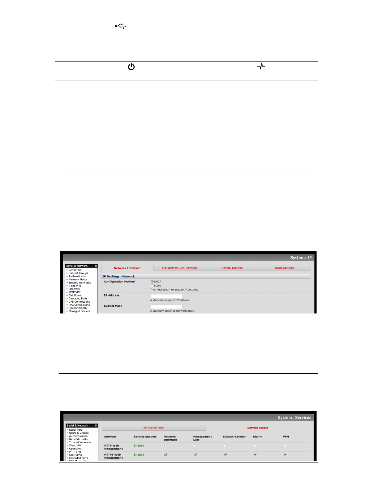
Ø Select System: IP then Network Interface (
NET1)
and check DHCP or
Static for Configuration Method
The appliance’s second Ethernet port is inactive by default. To activate:
Ø Select Management LAN Interface
(NET2)
and uncheck Disable
Ø Enter an IP Address and Subnet Mask – for OOB only mode this may be a
secondary management network; for IP Passthrough mode, select an unused
private network
Note: The appliance’s firewall determines which protocols and services can be
used to access which ports and devices. By default only HTTPS and SSH access is
enabled to the appliance itself. Use the Service Access menu on System: Services
to change settings for the appliance itself (and for connected serial ports).
Page 3

Step!4! Connect!the!cellular!modem
Note: In OOB only mode the cellular modem may be always-on, or configured to
start and stop dynamically (e.g. in response to a loss of primary network connectivity).
For an overview of failover configurations, refer to the
Knowledge Base FAQ
article
Automatic failover to alternate broadband, cellular or dial-out Internet
connection. In IP Passthrough mode, the cellular connection must remain always-on.
To set up an
always-on
cellular connection:
Ø Select System: Dial then the Internal Cellular Modem tab
Ø Select Enable Dial-Out, enter the carrier’s APN and optionally a Username
and Password
You may also need to use alternate DNS servers from those provided by your carrier:
Ø Check the Override Returned DNS Servers box and enter the IP of the DNS
servers into the fields provided
Note: Your cellular carrier may have provided you with connection details.
However, you generally will only need to enter the APN and leave the other fields blank.
If provided a PIN code you may need to use it to unlock the SIM card.
Ø Click Apply and a data connection will be established with your cellular carrier
Ø Select Status: Statistics then the Failover & Out-of-Band tab
Ø Verify the Connection Status of Internal Cellular Modem is
Connected
and
note your allocated IP Address (take note if it’s a private IP address)
Ø At any time you may view the cellular signal strength (RSSI) from the Cellular
tab of the Status: Statistics page – an RSSI of -100 dBm and less is
unacceptable
coverage, -99 to -90 is
weak to medium
coverage, -89 to -70 is
medium to strong
coverage, -69 and greater is
very strong
coverage
Note: Cellular modem status is also shown by the cellular status and signal
strength LEDs. The cellular status LED indicates the state of the cellular data connection:
off for no connection, blinking while establishing, and on while established. Cellular
coverage is indicated by how many signal strength LEDs are lit: four (
very strong
), three
(
strong
), two (
medium
), one (
weak
), zero (
unacceptable
)
If you have been allocated a
public IP address
, you can now access the appliance’s
HTTPS and SSH services directly. If you have a
dynamic public IP address
that changes
each time the appliance connects, you may configure the appliance’s Dynamic DNS
client in System: Dial, Internal Cellular Modem.
If you have been allocated a
private IP address
(i.e. in the 10.x.x.x, 100.64-127.x.x,
172.16-31.x.x or 192.168.x.x range), direct remote access may not be possible. Instead,
use
Call Home
or VPN to establish an outbound tunnel to an Opengear Lighthouse or
VPN server, to enable remote access over the tunnel.
Page 4

Note: For a detailed overview of remote access alternatives to an appliance with
a private IP address, refer to the
Knowledge Base FAQ
article Does my site need a
public IP address for OOB or Failover access?
Step!5! Configure!managed!devices
Ø Select Serial & Network: Serial Port to display the labels, modes and
protocol options currently set for each serial & USB port – to configure a port for
remote access to the managed device’s console:
o Configure the Common Settings to match the connected serial device
o Select the Console Server protocols (e.g. SSH, Telnet, Web Terminal)
that are to be used for the network connection to this console
o Click Apply – device consoles can now be accessed using your preferred
client (e.g. PuTTY, SecureCRT, OpenSSH) and in Manage: Devices
Ø User access policies may be configured locally in Serial & Network: Users &
Groups and/or remotely with a AAA server, refer to the
User Manual
for details
Step!6! Configure!IP!Passthrough!(optional)
Ø Select Serial & Network: IP Passthrough to transparently bridge the cellular
IP settings and data traffic to a downstream Ethernet router
o Check Enable and select Internal Cellular Modem as the Modem
o Select Management LAN as the Interface
o If your router has issues accepting the cellular network settings via DHCP,
check Enable Force Subnet Mask and enter Force Subnet Mask of 24
o To access to ACM7004-2-L itself (e.g. for OOB management) using the
cellular IP address, check Intercept Enabled for the desired services
Note: To use Service Intercepts, the ACM7004-2-L
must not have a non-
cellular default route installed
. Ensure both Serial & Network: IP: Network
Interface and Management LAN Interface are set to Static and Default
Gateway fields are blank.
o Click Apply
Ø Ensure your downstream router’s secondary WAN Ethernet is connected to
NET2
and is set to receive network settings via DHCP, to automatically complete setup
Step!7! Other!modes!and!functions!
Please refer to the
User Manual
for details other advanced features, such as cellular
failover, PDU (RPC) and UPS power management, environmental monitoring, logging,
Auto-Response
alerting and more.
Please register your product to activate the warranty and to
automatically receive advice of future firmware updates. Go to:
http://opengear.com/product-registration
 Loading...