

Page 1
ACM5504-5-GV-I Quick Start (520040-Rev 1.3) Page 1
ACM5504-5-GV-I
Quick Start Guide
Thank you for purchasing the ACM5504-5-GV-I management gateway. This Quick Start
walks you through installation and configuration. More details are available in the
User
Manual
which can be downloaded from
http://opengear.com/documentation
.
Step1 Check kit contents
ACM5504-5-GV-I device. External rack and DIN rail mount
tabs. Green connector block and 3G antenna. UTP cables.
Straight (319014) & crossover (319015) DB9F-RJ45S.
Straight (319016) DB9M-RJ45. Quick Start. 12VDC power
pack.
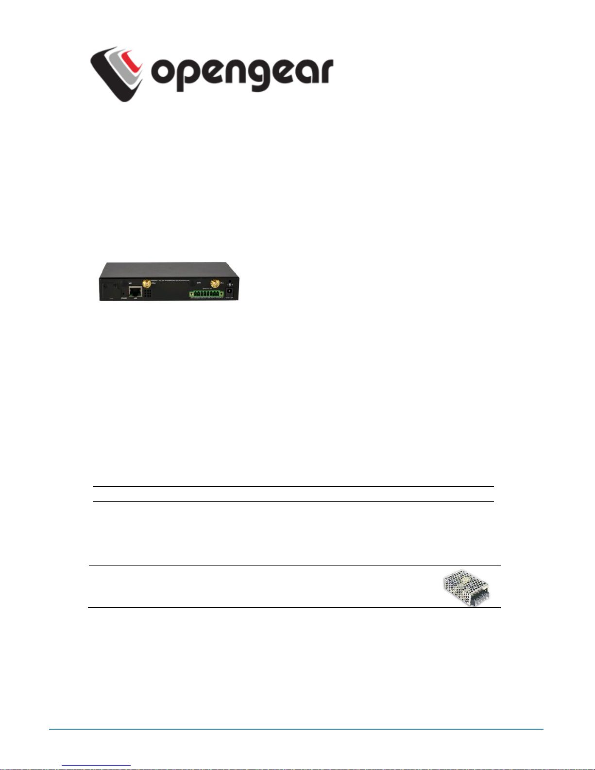
Step 2 Configure the hardware
Attach rubber feet to base. Also attach the desired mounting tab and screw the
3G antenna on to the main
Cell (M)
connector If you have purchased a diversity
or GPS antenna, screw it on to Cell A
Connect the Ethernet
LAN
port to your network. Connect your management LAN
devices to the
ETHERNET 1-4
ports
Plug your serial console devices into
SERIAL 1-4
(all Cisco RJ45 pin-out).
Connect your USB devices to the two
USB
ports
Plug in the green screw terminal block and attach external sensors and DIO
Note: Refer to ACM5500-I Addendum for RS422/485 and DIO details
Apply power. The ACM5504-5-GV-I can now be powered externally by either:
connecting the provided external power pack to the
12VDC
barrel socket or
connecting an external 9 to 24 VAC source to the
12VDC
barrel socket or
connecting +9V to 30 VDC to
DC PWR
and
GND
on the green terminal block
Note: If you ordered the -SDC option you’ll have an external DC-DC
power converter (input voltage +/- 36V DC to 72V DC. The
converter power cable/ connector plugs into the
12VDC
socket
The ACM5504-5-GV-I is ready for activation when the PWR status LED on the front panel
of the unit is lit steady, and the H/B (heartbeat) LED is flashing.
Step 3 Set up the appliance
The default IP Address is
192.168.0.1
(subnet mask
255.255.255.0
). With a web browser
on any computer that is network connected to the ACM5504-5-G-I:
Page 2

ACM5504-5-GV-I Quick Start (520040-Rev 1.3) Page 2
Enter https://192.168.0.1 into the address bar
Note: The
LAN
connected computer must have an IP address in the same network range
(192.168.0.xxx) as the ACM5504-5-GV-I. If this is not convenient, you can use
the ARP Ping command to set the IP address. Refer to the User Manual or online
FAQ for details. The ACM5504-5-GV-I also has DHCP enabled by default, so it will
automatically accept any network IP address assigned by any DHCP server on
your network. It will then respond at both 192.168.0.1 and its DHCP address
o Log in using the default system user name
root
and the password
default.
A
Welcome screen listing the basic configuration steps is displayed
It is recommended that you set up a new Administrator user (in the
admin
group with
full access privileges) and login as this new user for all ongoing administration functions
(rather than continuing as
root
).
Select System: Administration. Enter and confirm a new System Password
and click Apply
To assign your ACM5504-5-GV-I a static IP address or to permanently enable
DHCP on the primary Ethernet network, select System: IP then Network
Interface and check DHCP or Static for Configuration Method. Leave the
Failover Interface set to
None
Configure the RMM appliance connectivity:
Configure the serial port settings and enable the desired protocols and logging
levels via Serial & Network: Serial Port
Attached USB devices are auto-configured so you can access to USB console
ports, modems or external USB flash (the ACM5504-5-GV-I also has an internal
4GB flash)
You may also enable SSH tunneled access through the ACM5504-5-GV-I to
locally networked devices (
hosts
) using Serial & Network: Network Hosts
o Configure user access to serial ports via Serial & Network: Users & Groups
Step 4 Connect the cellular modem
Select the Internal Cellular Modem tab on the System: Dial menu. The
ACM5504-GV-I supports both OTASP (
Over-the-Air Service Provisioning
where
modem specific parameters can be retrieved via a call to a special phone number)
and a manual process where the phone number and other parameters can be
entered manually.
o For OTASP, enter *22899 as the number to be dialed (for Verizon)
Page 3

ACM5504-5-GV-I Quick Start (520040-Rev 1.3) Page 3
o For manual activation enter the MSL, MDN and MSID values. Verizon
have been known to use an MSL of 000000 and the phone number
assigned to the ACM5504-GV-I as both the MDN and MSID
Click Activate. If no errors occur you will see a valid phone number being placed
in the NAM Profile Account MDN field (Cellular page on Status: Statistics)
Enable the Internal Cellular Modem by entering the carriers phone number
(which defaults to #777)
You may also need to use alternate DNS servers from those provided by your carrier:
Enable Override DNS. Then check the Override returned DNS Servers box
and enter the IP of the DNS servers into the spaces provided.
Check Apply and a radio connection will be established with your cellular carrier.
Out-of-band access
is enabled, so the cellular modem connection is always ON.
Verify the
Connection Status
in the Statistics - Failover& Out-of-Band tab is
shown as
Connected
. You can also check your allocated
IP address
You can measure the received signal strength
RSSI
from the Cellular
Statistics page on the Status: Statistics screen. -99 dbm to –90 dbm = Weak
Coverage, -89 dbm to – 70 dbm = Medium, -69 dbm or greater = Strong
Note: You can also see the connection status from the WWAN LED. OFF is shown when in
reset mode or not powered. When powered, it will go ON and while searching for
service it will flash off briefly every 5 seconds. Once a radio connection has been
established with your cellular carrier (ie, after an APN has been properly
configured) the WWAN LED will blink rapidly
Step 5 OoB access
To directly access the ACM5504-5-GV-I, it needs a public IP address and must not have
SSH access firewalled. Almost all carriers offer corporate mobile data service/plans with a
Public (static or dynamic) IP address. These plans often have a service fee attached.
If you have such a static Public IP address plan, you can now try accessing the
ACM5504-5-GV-I using the Public IP Address provided by the carrier. However, by
default, only HTTPS and SSH access is enabled on the OoB connection. So you
can browse to the ACM5504-5-G-I, but you cannot
ping
it
If you have a dynamic Public IP address plan, then a DDNS service will need to
be configured. Once this is done, you can then also try accessing the ACM5504-5GV-I using the allocated domain name
If your service by default assigns a dynamic Private IP address to your 3G device then
this IP address is not visible across the Internet.
With such a plan, the Failover & Out-of-Band
tab on the Status: Statistics
page, will show your carrier allocated a Private
IP Address
(i.e. in the range
10.0.x.x, 172.16.x.x or 192.168.x.x)
For an inbound OoB connection with such a plan, you will need to use Call Home
with a VCMS/CMS6110 or set up a VPN connection
In this default out of band access mode, the connection to the carrier cellular network
is always on - awaiting any incoming access to the ACM5504-5-GV-I or attached serial
consoles/network hosts.
Page 4

ACM5504-5-GV-I Quick Start (520040-Rev 1.3) Page 4
An alternative is failover mode. This will tell the internal cellular connection to remain idle
in a low power state. Only when primary and secondary probes are not successful will it
connect to the cellular carrier (refer to the User Manual)
Step 6 Enable cellular router features
The ACM5504-5-GV-I can provide cellular routing (although this is disabled by default). In
this mode connection to the carrier cellular network is always on, but IP traffic is selectively
routed between the cellular connected network and the local Ethernet network (LAN):
Select the Forwarding & Masquerading tab on System: Firewall
Network Forwarding
allows devices on the local private LAN to IP connect
through to the public network. To enable, check Dialout/Cellular to be enabled
as the
Destination Network
for the Network Interface
Source Network
IP Masquerading
allows devices on the LAN to hide behind and share the one
public IP address when cellular connecting to the public network. To enable check
Enable IP Masquerading (SNAT) on Dialout/Cellular
Configure Port Forwarding and set Port Rules so external users can
selectively initiate connections to the masqueraded devices on the LAN
Set the Service Access rules for routed connections to the ACM5504-5-GV-I
itself
Configure the devices on the LAN with new
Gateway
and
DNS
settings
Step 7 Other Functions
The ACM5504-5-GV-I also offers advanced functions including
an Automated Response,
Alerts & Logging
facility, management of third party UPSs with
Manage: Power, Serial Port
Cascading, Authentication, Trusted Networks, Secure Tunneling, Distributed Monitoring
,
Custom Scripting
and a
Command Line
interface. Refer to the
User Manual
.
Please register your product to activate the warranty and
to automatically receive advice of future firmware updates. Go
to:
http://opengear.com/product-registration.html
 Loading...