

4MP/8MP IP
DOME CAMERA
HARDWARE MANUAL
36876AE 1

OE-C7084-AWR / OE-C7088-AWR 4MP/8MP IP Dome Camera
User Manual
Manual Edition 36876AE – FEBRUARY 2021
©2021, OPENEYE
All Rights Reserved.
No part of this documentation may be reproduced in any means, electronic or mechanical, for any
purpose, except as expressed in the Software License Agreement. OpenEye shall not be liable for
technical or editorial errors or omissions contained herein. The information in this document is subject to
change without notice.
The information in this publication is provided “as is” without warranty of any kind. The entire risk arising
out of the use of this information remains with recipient. In no event shall OPENEYE be liable for any
direct, consequential, incidental, special, punitive, or other damages whatsoever (including without
limitation, damages for loss of business profits, business interruption or loss of business information),
even if OPENEYE has been advised of the possibility of such damages and whether in an action or
contract or tort, including negligence.
This documentation is copyrighted. All other rights are reserved to OPENEYE. OPENEYE, and OpenEye, are
registered trademarks of OPENEYE in the United States and elsewhere; Windows, and Windows 10
Embedded are registered trademarks of Microsoft Corporation. All other brand and product names are
trademarks or registered trademarks of the respective owners.
OPENEYE
Liberty Lake, WA ● U.S.A.
2

Important Safeguards
1. Read Instructions
Read all of the safety and operating instructions before using the product.
2. Retain Instructions
Save these instructions for future reference.
3. Attachments / Accessories
Do not use attachments or accessories unless recommended by the appliance
manufacturer as they may cause hazards, damage product and void warranty.
4. Installation
Do not place or mount this product in or on an unstable or improperly supported
location. Improperly installed product may fall, causing serious injury to a child or
adult, and damage to the product. Use only with a mounting device recommended by
the manufacturer, or sold with the product. To insure proper mounting, follow the
manufacturer's instructions and use only mounting accessories recommended by
manufacturer.
5. Power source
This product should be operated only from the type of power source indicated on the
marking label.
Precautions
Operating
Before using, make sure power supply and others are properly connected.
While operating, if any abnormal condition or malfunction is observed, stop using the
camera immediately and then contact your local dealer.
Handling
Do not disassemble or tamper with parts inside the camera.
Do not drop or subject the camera to shock and vibration as this can damage
camera.
Care must be taken when you clean the clear dome cover. Scratches and dust will
ruin the image quality of your camera. Do not use strong or abrasive detergents
when cleaning the camera body. Use a dry cloth to clean the camera when it is
dirty. In case the dirt is hard to remove, use a mild detergent and wipe the camera
gently.
Installation and Storage
Do not install the camera in areas of extreme temperatures in excess of the
allowable range; install the camera in areas with temperatures within the
camera’s operating temperature, including the following: -31 ~ 140 ºF (-35 ~ 60
ºC).
Avoid installing in humid or dusty places. The relative humidity must be below 90%.
Avoid installing in places where radiation is present.
Avoid installing in places where there are strong magnetic fields and electric signals.
36876AE 3
Avoid installing in places where the camera would be subject to strong vibrations.
CAUTION: TO REDUCE THE RISK OF ELECTRIC SHOCK,
DO NOT REMOVE COVER (OR BACK).
NO USER-SERVICEABLE PARTS INSIDE.
REFER SERVICING TO QUALIFIED SERVICE PERSONNEL.
CAUTION
RISK OF ELECTRIC SHOCK
DO NOT OPEN
Never face the camera toward the sun. Do not aim at bright objects. Whether the
camera is in use or not, never aim it at the sun or other extremely bright objects.
Otherwise the camera may be smeared and damaged.
Regulation
This device complies with Part 15 of the FCC Rules. Operation is subject to the following two
conditions: (1) this device may not cause harmful interference, and (2) this device must accept
any interference received, including interference that may cause undesired operation.
Compliance is evidenced by written declaration from our suppliers, assuring that any potential
trace contamination levels of restricted substances are below the maximum level set by EU
Directive 2002/95/EC, or are exempted due to their application.
Warning
DANGEROUS HIGH VOLTAGES ARE PRESENT INSIDE THE ENCLOSURE.
DO NOT OPEN THE CABINET.
REFER SERVICING TO QUALIFIED PERSONNEL ONLY.
Caution
4

Table of Contents
Table of Contents .......................................................................................................... 5
Introduction ................................................................................................................... 7
Overview ................................................................................................................................................... 7
Product Features .................................................................................................................................. 7
Getting Started .............................................................................................................. 8
Box Contents ............................................................................................................................................ 8
Camera Overview ..................................................................................................................................... 9
Camera Dimensions ............................................................................................................................. 9
Connections ........................................................................................................................................ 10
Waterproof Cable ............................................................................................................................... 11
Ethernet Cable Connections............................................................................................................... 11
Power .................................................................................................................................................. 11
NETWORK CAMERA MANAGER .................................................................................... 12
Launching Network Camera Manager ................................................................................................ 12
Apex Windows Platforms ................................................................................................ 12
Linux Platforms ............................................................................................................... 12
Finding Network Devices .................................................................................................................... 12
Username and Password ................................................................................................................... 13
Viewing a Network Camera ................................................................................................................ 13
Live View ................................................................................................................................................ 14
Setup....................................................................................................................................................... 15
Basic Camera Settings ....................................................................................................................... 15
Network Settings ................................................................................................................................ 16
IP Address (DHCP/Static IP) ........................................................................................... 16
IPv6 Address Configuration ............................................................................................ 16
Port-Mapping ................................................................................................................... 18
Streaming Settings ............................................................................................................................. 22
Picture Settings .................................................................................................................................. 27
Scenes ............................................................................................................................ 27
Image Enhancement ....................................................................................................... 29
Exposure ......................................................................................................................... 30
Smart Illumination ........................................................................................................... 32
White Balance ................................................................................................................. 32
Advanced ........................................................................................................................ 32
Events Settings ................................................................................................................................... 35
Motion Detection ............................................................................................................. 35
Audio Detection ............................................................................................................... 38
Alarm Input ...................................................................................................................... 40
Alarm Output ................................................................................................................... 41
STORAGE SETTINGS ...................................................................................................................... 42
Security Settings ................................................................................................................................. 43
Add User ......................................................................................................................... 43
Edit User ......................................................................................................................... 43
Delete User ..................................................................................................................... 43
Maintenance ....................................................................................................................................... 47
Software Upgrade ........................................................................................................... 48
36876AE 5

Device Restart ................................................................................................................. 48
Configuration Management ............................................................................................. 48
Diagnosis Information ..................................................................................................... 48
Logout .......................................................................................................................... 49
6

Introduction
OVERVIEW
The OE-C7084-AWR and the OE-C7088-AWR are high power, outdoor IP dome cameras equipped with a
4MP or an 8MP 2.8~12mm motorized autofocus lens that provides crisp and clear images. These
cameras include WDR and True Day/Night for improved low light performance, and adaptive IR
technology to prevent overexposure of objects close to the camera. Network throughput and storage
requirements are reduced thanks to H.264 smart encoding technology which dynamically compresses
the camera’s video to reduce its bitrate. These cameras are IP67 rated and function down to -31°F
making them a perfect fit for extreme weather installations. In addition, these cameras can be fully
powered over PoE, reducing labor costs by eliminating additional cabling requirements.
All OpenEye IP cameras are fully ONVIF™ compliant and are compatible with the OpenEye Web Services
platform, allowing multiple users to view high quality images and perform remote setup using a Web
browser.
PRODUCT FEATURES
8MP (4K) maximum resolution (OE-C7088-AWR only)
IP67 outdoor rating
2.8~12mm motorized autofocus lens
IK10 vandal resistant rating
True Day / Night
True Wide Dynamic Range
H.264 with Smart Compression
1/2” Progressive CMOS image sensor
ONVIF™ Profile S compliant
3-Axis Gimbal Positioning
Getting Started
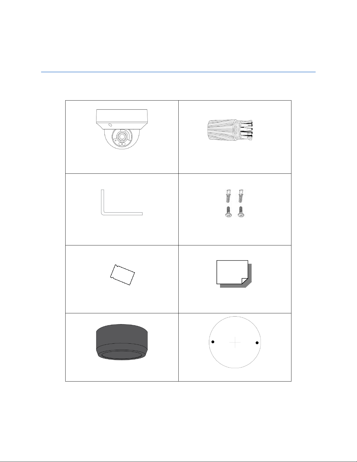
OE-C7084-AWR or
Waterproof Cable Connector
Torx Tool
Self-Tapping Screws and
Plastic Anchors
Desiccant Packet
Quick Start Guide
Paintable Dome Cover
Mounting Template
BOX CONTENTS
Before proceeding, please check that the box contains the items listed here. If any item is missing or has
defects, DO NOT install or operate the product and contact your dealer for assistance.
OE-C7088-AWR IP Dome Camera
8
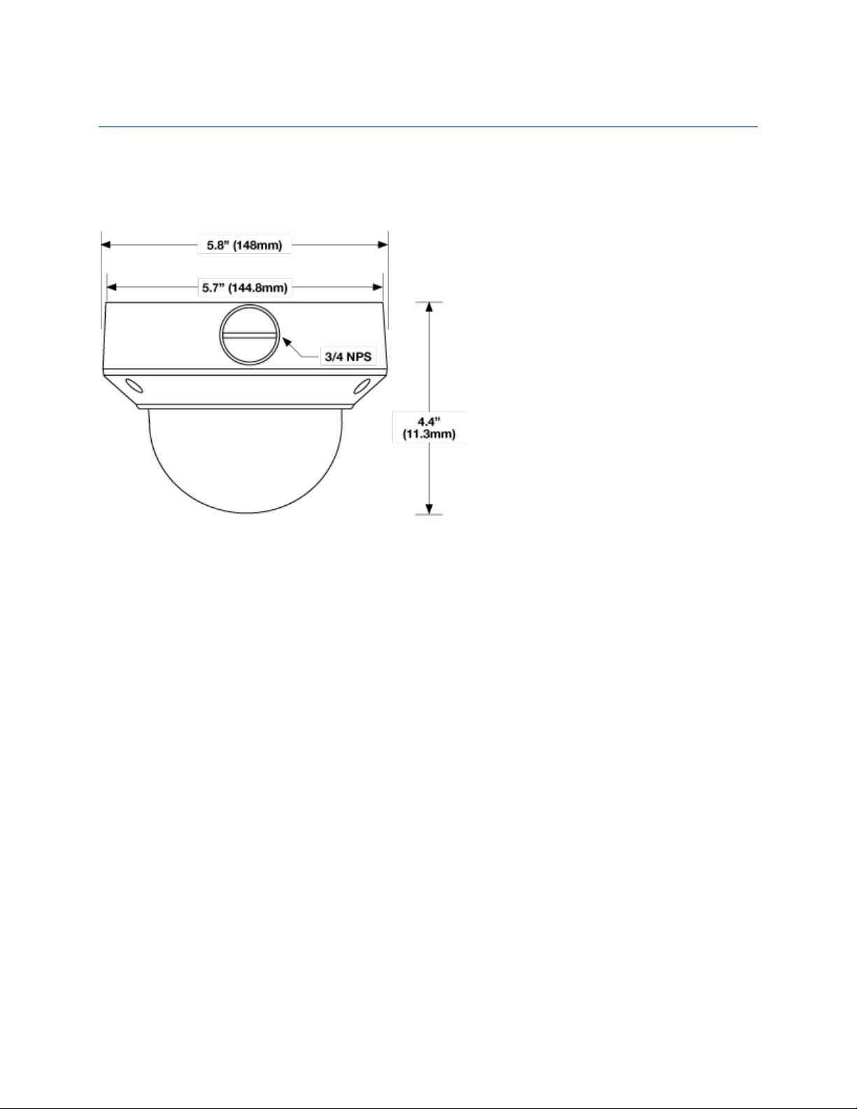
CAMERA OVERVIEW
Before installing or connecting the camera, please refer to this section and complete preparations for
camera setup.
CAMERA DIMENSIONS
36876AE 9
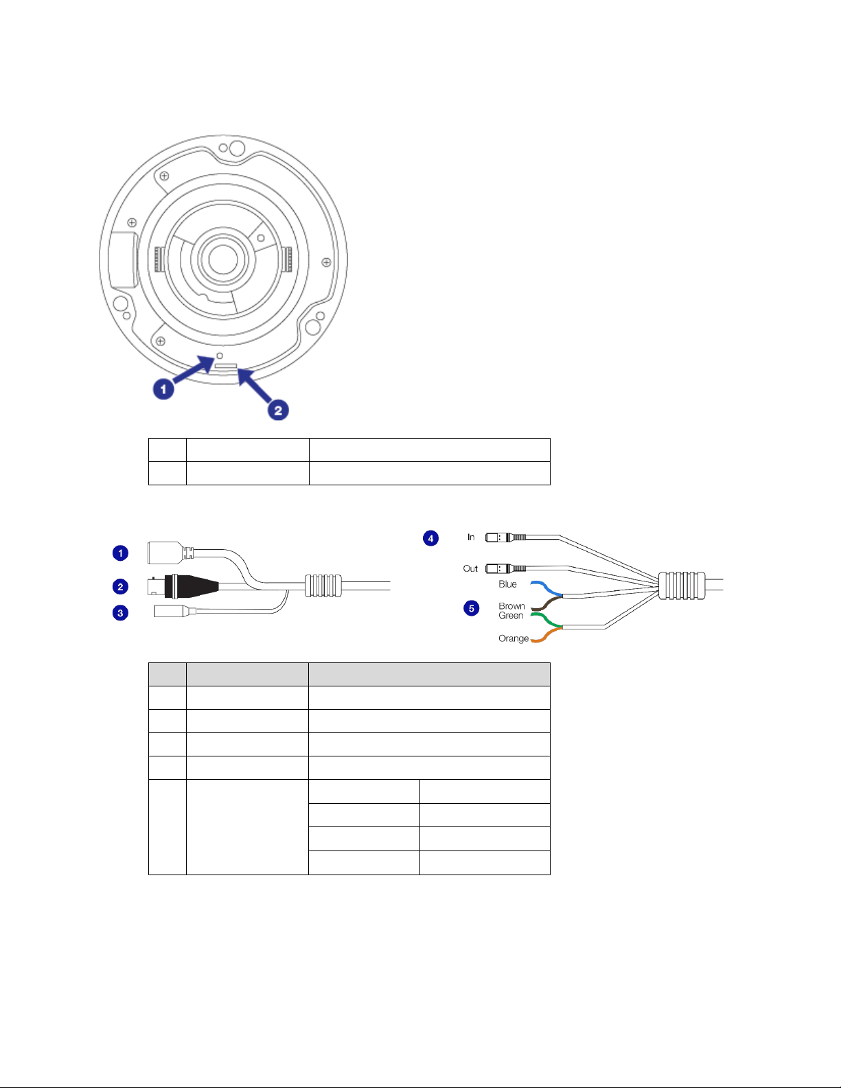
CONNECTIONS
Pin
Connection
Definition
1 Reset Button For defaulting camera to factory settings
2 microSD Slot microSD card for edge storage (128 GM)
1 RJ-45 For network and PoE connections
2 BNC For analog video spot out
3 Power (12vDC) Power connection
4 Audio In/Out Audio Out is reserved
Blue Ground
5 Alarm I/O
Brown Alarm Input
Green Alarm Out -
Orange Alarm Out +
10
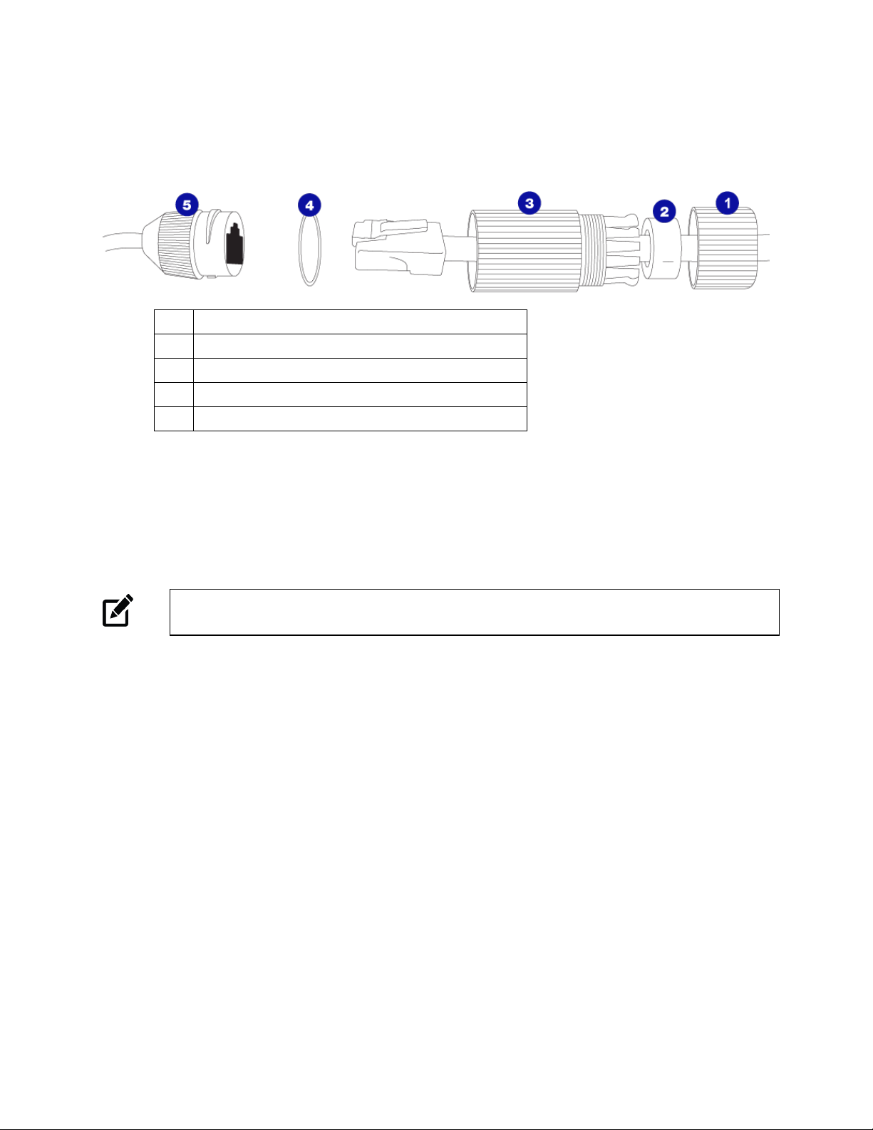
WATERPROOF CABLE
1 Thread lock cap
2 Rubber plug
3 RJ45 enclosure
4 Rubber “O” ring
5 Camera cable
ETHERNET CABLE CONNECTIONS
Connect a network cable to the camera using the RJ45 input and connect the other end of the cable to
your network switch or recorder.
Note If you are connecting the camera directly to a recorder, a crossover cable is necessary for
most configurations.
POWER
This camera is compatible with 12vDC and Power over Ethernet (PoE). Connect power to the camera
using the provided power connector lead. If you are connecting 12vDC power, verify the polarity of the
power connection. If you are using PoE, make sure the Power Sourcing Equipment (PSE) is in use in the
network.
36876AE 11
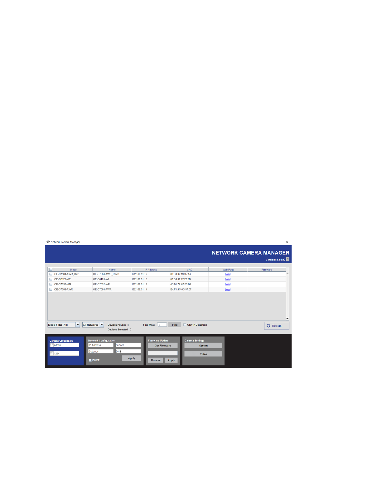
NETWORK CAMERA MANAGER
OpenEye Network Camera Manager (NCM) is a software tool that allows you to quickly and easily
connect and configure your OpenEye IP Cameras. This software allows you to apply the camera
password, assign IP addresses, configure video settings, and update firmware on multiple cameras at
once.
NCM is pre-installed on all OpenEye Recorders and is also available for download www.OpenEye.net for
installation on your personal computer or laptop. Network Camera Manager is a Java application, this
allows it to be installed on Windows and Linux operating systems.
LAUNCHING NETWORK CAMERA MANAGER
Apex Windows Platforms
Network Camera Manager can be found on the desktop.
Linux Platforms
In the Apex Settings menu, go to the Cameras page and click Advanced.
FINDING NETWORK DEVICES
Click Refresh to reload the Device List.
To narrow your search by Camera Model or Network, use the Model Filter and Networks dropdowns.
A Mac Address search is also available if you are looking for a specific device.
12
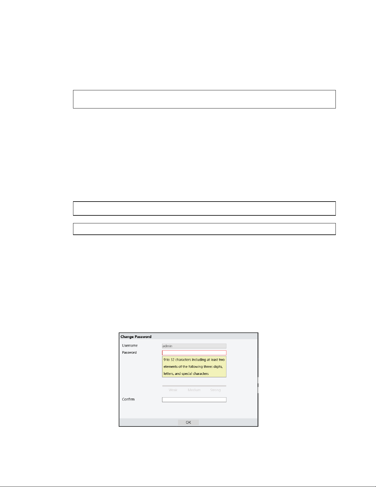
USERNAME AND PASSWORD
*OpenEye IP cameras ship without a default password.
Username: admin
Note Passwords must be 9-32 characters and include at least two of the following three elements:
Digits, Letters, and Special Characters.
The admin user password can be set using the following methods:
1. OpenEye recorders running Apex 2.1 or newer will automatically set a new unique password
if:
• Connected to an M-Series recorder with a built in PoE switch.
• Connected to a network switch through the camera network port and selected then
added in setup, if a new password has not already been set.
2. Connect to the camera directly through a Web Browser and follow the onscreen prompts.
3. Use the Network Camera Manager (NCM) Utility.
Note The NCM Software Manual can be found at https://www.openeye.net/ncm-manual.
Note Refer to your Apex recorder manual or quick start guide for instruction on adding cameras.
VIEWING A NETWORK CAMERA
Click Load in the row of the desired camera.
Enter a new Admin password.
• Passwords must be 9-32 characters and include at least two of the following three
elements:
o Digits
o Letters
o Special Characters
All special characters are allowed.
36876AE 13
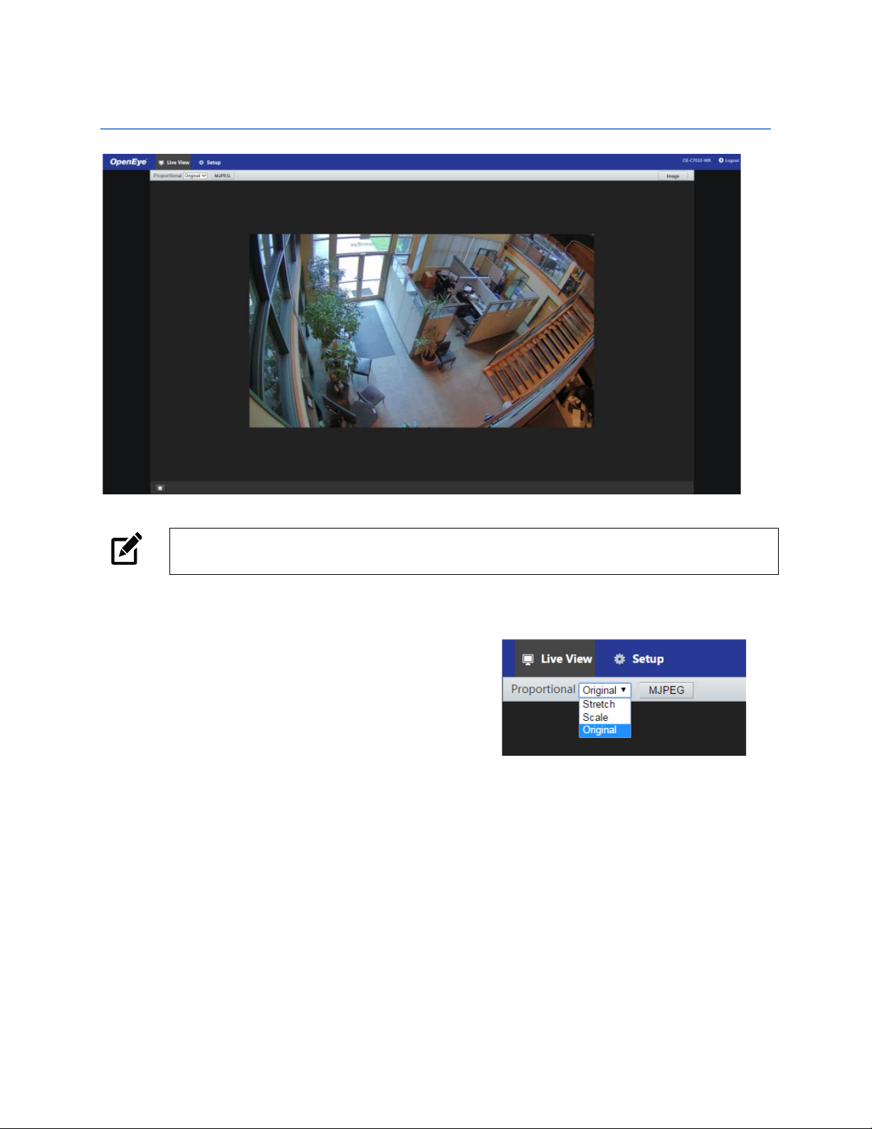
LIVE VIEW
Note Live view is broadcast in MJPEG pass-through. Stream settings will be broadcast to your
recording device according to the selected Codec type.
Setup – View additional camera settings.
Proportional – Dropdown menu with Live View image
options including:
Stretch: Fit the camera image to the entire
viewing window without scaling the image
proportionately to the original view.
Scale: Fit the camera image to the entire viewing
window, including scaling the image
proportionately to the original view.
Original: The camera image will fit in the viewing window in accordance with the default
image resolution.
Image – Shortcut to camera Image Setup menu.
Logout – Log out of the currently displayed camera.
14
SETUP
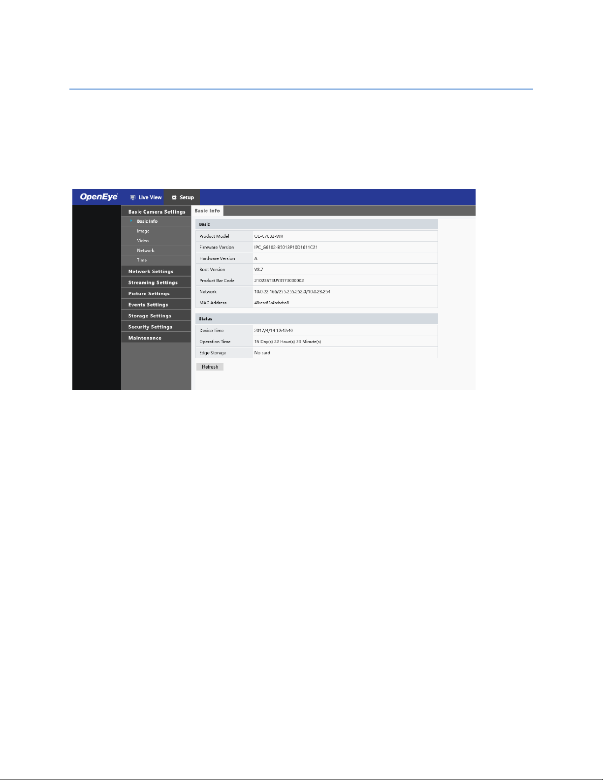
BASIC CAMERA SETTINGS
Basic Info
The Basic Info tab displays the product model, firmware, network, and MAC address for the connected
camera, along with the current camera status.
The Image, Video, Network, and Time tabs are shortcuts to the more advanced menu options. For more
information, see the appropriate sections later in the manual.
36876AE 15

NETWORK SETTINGS
Network
The Network tab allows you to configure the
connected camera network settings.
IP Address (DHCP/Static IP)
You can use the dropdown menu to choose to use a
Static (fixed) IP address, PPPoE, or a dynamic IP
address (assigned by a DHCP server or router) for
the camera.
To set up a new static IP address:
1. Select the Static IP dropdown option.
2. Type a new IP address in the IP address box.
3. Type a new address in the Subnet Mask box.
4. Type a new address in the Default Gateway box.
5. Click Save to confirm the new setting.
IPv6 Address Configuration
To enable IPv6, select Enable IPv6 and click Save. See your network administrator if you are unsure of
your network configuration.
When using static IP address to log in to the IP Camera, you can access it either through OpenEye IP
Finder software or type the IP address directly in the address bar of your web browser.
IP Address – Default IP with no DHCP server is set to 192.168.51.2.
Subnet mask – Used to determine if the destination is in the same subnet. The default value is
255.255.255.0.
Default gateway – Used to forward frames to destinations on different subnets or for internet access.
Web Server port – Defines the port that Internet Explorer uses to connect over the web and view video. If
this port is changed then the new port must be defined when attempting to web connect (ex: if your
camera’s IP address is 192.168.0.100 and you change the web port to 8001, then you must type
http://192.168.0.100:8001 in your browser).
16

DNS
Set your Prefered DNS and Alternate DNS server.
36876AE 17

Port
HTTP Port – Configure your relevant port number.
Note If the HTTP port number has been occupied already, a “Port conflicts” message will display.
Ports 23, 81, 82, 85, 3260, and 49152 are occupied by default.
HTTPS Port – The default HTTPS Port is 443; setting range: 1024 ~65535.
RTSP Port – The default RTSP port is 554; setting range: 1024 ~65535.
Note No port number can be used in duplication on more than one item.
Port-Mapping
To enable Port-Mapping:
1. Check the Port-Mapping Enable checkbox.
2. Use the Mapping Type dropdown menu to select a type.
3. If selecting Manual, the external ports must be configured.
Note If the configured port is already occupied, then the Status will show as inactive and a new port
must be selected.
4. Click Save.
18

DDNS
DDNS (Dynamic Domain Name Service) is a service that allows a connection to an IP address using a
hostname (URL) address instead of a numeric IP address. Most ISPs use Dynamic IP Addressing that
frequently changes the public IP address of your internet connection; this means that when connecting to
the camera over the internet, you need to know if your IP address has changed. DDNS automatically
redirects traffic to your current IP address when using the hostname address.
Enable DDNS – Select the check box to enable DDNS.
DDNS Type / Server Address – Enter the DDNS type provided by your DDNS server.
Domain Name – Type the registered domain name in the field.
Username/E-mail – Type the username or e-mail required by the DDNS provider for authentication.
36876AE 19

FTP
Use FTP (file transfer protocol) to upload snapshots from network cameras to a specified server.
To configure FTP:
1. Enter the Server IP address and Port Number.
2. Enter the Username and Password for the upload account.
3. Enable Upload Images and/or Overwrite Storage, and set the Overwrite Image
4. Click Save.
threshold.
20

The camera can send an e-mail via Simple Mail Transfer Protocol (SMTP) when a variety of events occur.
SMTP is a protocol for sending e-mail messages between servers. SMTP is a relatively simple, text-based
protocol, where one or more recipients of a message are specified and the message text is transferred.
Two sets of SMTP accounts can be configured. Each set includes SMTP Server, Account Name,
Password and E-mail Address settings. For SMTP server, contact your network service provider for more
specific information.
36876AE 21

STREAMING SETTINGS
Video
The Video Settings menu configures the camera’s basic settings, including frame rate, bit rate, and the
image quality.
To configure the camera streams:
1. Use the dropdown menus to configure the Video Compression, Frame Rate Bitrate Type,
GOP, and Smart Encoding.
2. Enable and configure the Sub-Stream if desired.
3. Click Save to save each selection.
Smart Encoding – Turn on Smart Encoding to enable H.264+ encoding to reduce bit rate.
Resolution and Frame Rate – Use the dropdown menu to select the base resolution and frame rate for
the main stream.
Note Higher frame rate will increase video smoothness, but will increase file size and bandwidth
usage. Lowering the frame rate will conserve file size and bandwidth usage at the expense of
video smoothness.
Video Compression – H.264, H.265, and MJPEG are available for video compression.
Image Quality – If the Encoding Mode is set to VBR, you can adjust the quality level for images by moving
the sliding bar. The Quality side of the bar improves video quality, and the Bit Rate side of the bar reduces
Bit rate.
I-Frame Interval / GOP – The Group of Pictures setting allows you to modify the frame structure of the
video stream. This setting changes the frequency of the I-frames that occur within the stream of Pframes. Increasing this number increases the number of P-frames between each I-frame, decreasing the
file size of the stream, but increasing the risk of video decoding errors. It is recommended setting the
GOP to be approximately twice the frame rate.
22

Smoothing – Configure the amount of video smoothing. Moving the sliding bar toward Smoothing
increases the level of smoothing but may affect image quality.
Smart Encoding – The camera may be equipped with smart compression (H.264+), which drastically
reduces the overall bit rate.
Note In a poor network environment, you can enable smoothing to get more fluent video.
Snapshot
The Snapshot tab is used to configure the settings for timed or continual snapshots.
To configure Snapshots:
1. Use the dropdowns to select the desired Resolution, Image Quality, Snapshot Interval,
and the Number of Snapshots.
2. If you desire Scheduled Snapshots, select Timed Snapshot Mode, and designate an
Interval.
3. Click Save.
36876AE 23

Region of Interest (ROI)
When Region of Interest (ROI) is enabled, the system ensures the image quality for the ROI first if the bit
rate is insufficient.
To enable ROI:
1. Check the Enable ROI checkbox.
2. Arrange the red ROI square as desired in the camera image. Click and drag to move the
square, and use the corner markers to expand the square. The interior of the ROI square
will be considered the ROI.
Your changes will be saved automatically.
24

Media Stream
You can display the established media streams from a camera. You can also set the camera to transmit
code streams by the UDP or TCP protocol to a specified IP address and port number.
Note Changes to the media stream will take effect after the camera has been restarted.
To configure media streams:
1. Click the + on the right side of the title bar and the Add Media Stream page will appear.
2. Select a Stream Type, and then set the IP Address and Port Number of the unicast or
multicast group for the decoding device that receives audio and video streams from
the camera.
3. Check the Enable Persistent checkbox if you want the device to establish the media
stream that you have just configured automatically upon each subsequent restart.
4. Click Save.
5. Click the Delete icon to delete a created media stream.
36876AE 25

26

PICTURE SETTINGS
Image
The Image tab allows you to configure the setting for the camera image as seen in Live View.
When adjusting your image settings, the changes will be saved automatically and will display in the
camera image preview window.
Scenes
Scene allows you to set the image parameters to achieve the desired image effects based on live video in
different environments.
To configure Scenes:
1. Click the Current checkbox of the desired Scene.
Note Select an option button to switch to the scene and display the corresponding image
parameters for the scene. The camera switches the current scene automatically when Enable
Auto Switching is selected.
2. Select a Screen Name from the dropdown, or select Custom and enter one of the
common options below.
Common – Recommended for outdoor scenes.
Indoor – Recommended for indoor scenes.
License Plate – Recommended for plate snapshots on roads.
High Sensitivity – Recommended for scenes with low light.
Highlight Supression – Recommended for scenes with intense light.
WDR – Recommend for scenes with high-contrast lighting, such as a window, corridor, front door, or
scenes that contain an indoor/outdoor contrast.
Vivid – Increases the saturation of the image based on the standard mode.
Bright – Increases the brightness of the image based on standard mode.
3. Use the Default Scene Pin icon to set the desired Scene as default.
36876AE 27

If auto-switching is enabled, the camera can switch to the scene automatically when the confition for
switching to a non-default scene is met.
28

Image Enhancement
Use the sliding scales to adjust the Image Settings, or set a numeric value in the value box.
The dropdown Image Rotation menu will rotate the camera image.
36876AE 29

Exposure
By default, the Exposure Mode is set to Automatic. Other options include Custom, Indoor 50hz, Indoor
60hz, and Manual. Using Custom or Manual allows you to manually configure the shutter and gain
control.
Shutter – Control the light that enters into the camera lens. A fast shutter speed is ideal for scenes with
fast movement.
Note You can set a shutter speed when Exposure Mode is set to Manual or Custom.
Gain – Controls the amplification of the signal from the camera sensor, allowing the camera to output
video signals according to the light conditions.
Note You can set this parameter only when Exposure Mode is set to Manual or Custom.
Slow Shutter – Improve image brightness in low light conditions.
Slowest Shutter – Set the slowest shutter speed that can be used during exposure.
Compensation – Customize the compensation up or down to get the optimal camera image.
Metering Control – Designate the way the camera measures the intensity of light.
Center-Weighted Average Metering: Prioritizes the middle section of the image and is most
useful when the subject is in the center of the scene or when the scene is evenly lit.
Evaluate Metering: Allows you to select a portion of the image to apply the metering control
to.
Spot Metering: Uses a small point in the center of the scene to meter exposure. This mode is
useful in scenes with bright back grounds or a large amount of contrast
Day/Night Mode –
Automatic/Day/Night: Allows you to set the camera to automatically switch between night
mode and day mode, set to On, or set to Off.
Day/Night Switching: Set the length of time before the cmera switches between day mode
and night mode after the conditions for switching are met.
WDR – Set WDR to Automatic, On, or Off and adjust the WDR sensitivity.
WDR Level – Improve the image by adjusting the WDR level. For areas of higher contrast, a WDR level of 7
or higher is recommended.
30

36876AE 31

Smart Illumination
Toggle Smart Illumination Enabled or Off, and then use
the dropdown menus to customize the Lighting Type,
Control Mode, and Illumination Level.
White Balance
Use the white balance setting to change color
representation in difficult lighting conditions.
Auto – White balance works within its color
temperature range and calculates the best-fit white balance.
Outdoor, Fine Tune, Sodium Lamp, and Locked – Advanced settings to customize your White Balance
based on the scene.
Note It is recommended to use Auto and Auto 2 to cover most use cases.
Advanced
Defog – Adjust the clarity of images captured in fog or haze conditions.
1. Use the Defog dropdown menu to turn Defog On or Off.
2. Slide the Defog Intensity bar to the desired position (1 is the minimum intensity and 5 is
the maximum intensity).
Note The Defog function is only available when WDR is disabled.
32

On-Screen Display
Up to 8 on-screen displays (OSD) can be configured for the camera image.
To add an on-screen display:
1. Check the Enable checkbox for the desired OSD.
2. Type the X and Y axis coordinates to set the OSD location on the camera image, or click
and drag the OSD to the desired location.
3. Click in the Overlay OSD Content column and use the dropdown menu to select the
desired OSD content.
4. If desired, use the Display Style options to further configure the OSD.
Note To view the OSD in the web browser Live View, you must refresh the browser after setting the
OSD for the changes to take effect.
36876AE 33

Privacy Mask
Add a privacy mask to your camera image to hide desired areas from view.
To add a privacy mask:
1. Click Add.
2. Click and drag the newly generated mask square to the desired location on the camera
image. Arrange and resize the mask square as desired.
Your changes will be saved automatically.
To delete a created privacy mask:
1. Select the desired mask from the Privacy Mask list.
2. Click Delete.
34

EVENTS SETTINGS
Alarms
Motion Detection
Motion detection is used to detect motion in a specified area during a period of time. The use of motion
detection requires setting a detection area, detection sensitivity, object size, and history. When these
requirements are met, the motion detection alarm will activate.
To configure Motion Detection:
1. Click and drag the detection box to the desired location on the camera image, and use
the corner markers to adjust the size of the detection box as desired.
2. Use the Sensitivity, Object Size, and Duration slider bars to adjust the motion detection
parameters as desired.
Sensitivity – This determines how many pixels have to change in order for the alarm to
consider motion to have occurred.
Object Size – This determines the area within the camera image that the motion must
exceed in order for the alarm to consider motion to have occurred.
Duration – This determines how long the camera image must be changing before alarm
considers motion to have occurred.
3. Set the Alarm Parameters.
Suppress Alarm – After an alarm is triggered, the same alarm will not be reported again
within the designated time.
Clear Alarm – After the alarm is triggered:
If the same alarm is not triggered within the set time, the alarm will be cleared and
the same alarm can be reported again.
If the same alarm is triggered within the set time, the alarm will not be cleared until
the suppress alarm time expires. Then the same alarm can be reported again.
36876AE 35

4. Select the Alarm Triggering Mode to occur once the motion detection alarm has
been triggered.
5. Click Save.
Alarm Output 1 – This will cause an alarm output from the camera to a third-party device
to act on the alarm.
Upload to FTP – The camera will automatically upload snapshots to the specified FTP
server when an alarm is triggered.
Note FTP function needs to be configured before the Alarm Upload to FTP setting is selected.
Trigger Storage – The camera will automatically start recording after an alarm is
triggered.
Note Post-recording time settings need to be configured before Trigger Storage is selected.
Trigger Email – The camera will automatically send snapshot to the specified email
address when an alarm is triggered.
Note Email setup needs to be configured before Trigger Email is selected.
The alarm schedule is used to arm or disarm motion detection alarms. This may be useful to prevent
unnecessary alarm triggers during business hours, for example.
To arm or disarm Motion Detection:
1. Check the Enable Schedule checkbox.
2. To make changes to the schedule, click Edit.
3. Specify the Start Time and End Time of the motion detection alarm.
4. If desired, check the Copy To checkbox, and the desired days of the week to copy the
motion detection alarm schedule to those days.
5. Click Save.
Note The Time axis of the Schedule table
is based off a 24-hour clock. “0” is
12:00 a.m. (midnight, start of day),
“12” is 12:00 p.m. (noon) and “24” is
12:00 a.m. (midnight, end of day).
In this example, the motion detection alarm is armed
from 0:00 (midnight, start of day) to 05:30 (5:30 a.m.)
then disarmed for normal business hours, and then
armed again from 17:30 (5:30 p.m.) to 24:00
36

(midnight, end of day) Monday through Friday. On Saturday and Sunday, the motion detection alarm is
armed 24 hours a day.
1.
36876AE 37

Audio Detection
The camera can detect input audio signal for exceptions. When the rise or fall of volume exceeds the set
limit, or when the input volume reaches the threshold, the camera reports an alarm and triggers the set
actions. Ensure that an audio input device is correctly connected to the camera and audio input is turned
on.
To configure Audio Detection:
1. Check the Enable Audio Detection checkbox.
2. Use the Detection Type dropdown to select a detection type, and then set the
Difference.
Rise Above – The alarm will trigger when the rise of volume exceeds the difference.
Falls Below – The alarm will trigger when the fall of volume exceeds the difference.
Passes – The alarm will trigger when the rise or fall of volume exceeds the difference.
Threshold – The alarm will trigger when the volume exceeds a threshold.
Note The “difference” refers to the numerical difference between two volumes. The ‘threshold’
refers to a maximum numerical value that must be exceeded for the alarm to trigger.
Audio Detection results are shown in real time. The red bars indicate the volume of the
audio alarm has reached the threshold.
3. Select the Alarm Triggering Mode to occur once the audio detection alarm has been
triggered. See the Motion Detection section for more information about the Alarm
Trigger Modes.
38
4. If desired, enable an Audio Detection schedule. See the Motion Detection section for
more information about the Alarm Schedule.

5. Click Save.
36876AE 39

Alarm Input
The camera can receive alarm information from a third-party device.
To configure Alarm Input:
1. Select the Alarm, the Alarm Name, and the Alarm ID.
2. Select Normally Open or Normally Closed, depending on the type of third-party alarm
input device.
3. Select the Alarm Triggering Mode to occur once the audio detection alarm has been
triggered. See the Motion Detection section for more information about the Alarm Trigger
Modes.
4. If desired, enable an Alarm Input schedule. See the Motion Detection section for more
information about the Alarm Schedule.
5. Click Save.
40

Alarm Output
After an alarm output is triggered by a motion detection alarm, audio alarm, or other third-party
configured alarm, the camera can trigger an alarm output to a third-party device.
To configure Alarm Input:
1. Select the Alarm and the Alarm Name.
2. Select Normally Open as the default Status and set the Duration.
3. If desired, enable an Alarm Input schedule. See the Motion Detection section for more
information about the Alarm Schedule.
4. Click Save.
Caution Follow the power-on sequence for alarm output third-party devices and cameras
5. Check that the alarm Status is set to Normally Open (default setting), and that the
camera and the alarm output device are powered off.
6. After completing the connection, power on the alarm output device first, and then
power on the camera.
carefully to avoid damaging camera components.
36876AE 41

STORAGE SETTINGS
OpenEye IP cameras include an integrated microSD™ card (Memory Card) slot that can be used to record
video or images. The card slot is compatible with a microSD™ card up to 128GB.
To
select the Memory Card as the Storage Medium, check the Enable checkbox.
Allocate Capacity – Determine the capacity allotment for recorded video and Snapshots.
Stream – Determine which stream will be recorded into storage.
When Storage is Full – Determine whether old storage will be overwritten, or if storage will stop once the
storage space is full.
Once the Storage Settings have been configured as desired, click Save.
Note Video recorded to the microSD card cannot be accessed through Video Management
Software. Video recorded to the microSD card must be accessed and exported directly from
the camera’s web interface.
42

SECURITY SETTINGS
User
Add User
The user name and passwords are limited to 32 characters with no spaces permitted. There is a
maximum of twenty user accounts.
1. Type the new Username and User Type.
2. Type a Password, and then confirm the password.
3. Click Save.
Edit User
1. Select the user name on the User list.
2. Click Edit.
3. In the resulting window, modify the Password and/or feature permissions.
4. Click Save.
Delete User
1. Select the user name on the User list.
2. Click Delete to remove the user.
3. Click OK in the confirmation window.
There is a momentary wait time while the Network Camera Manager saves parameters. When this period
is complete, the User will be deleted.
36876AE 43

Network Security
You can use the Network Security tab to set a secure channel for data transmission.
To configure Network Security:
1. Click Network Settings, and then click Port, and then enter the port number in the HTTPS
Port box.
2. Click Save.
3. Click Security Settings, and then click Network Security.
4. Check the Enable HTTPS checkbox, or click Browse to upload your custom SSL
certificate if desired.
5. Click Save.
Real Time Streaming Protocol (RTSP) is an application layer protocol. To transmit and control the audio
and video, set RTSP authentication in the web browser. Use the Authentication dropdown menu to select
the appropriate mode, and then click Save.
44

IP Address filtering allows you to configure access from specified IP addresses to your camera.
1. Check the Enable IP Address Filtering checkbox.
2. Select a Filtering Mode, and then click the + symbol to add the desired IP addresses to
the list.
Note If the Filtering Mode is set to Whitelist, only the specified IP addresses are allowed to access
the camera. If the Filtering Mode is set to Deny Access, the specified IP addresses are denied
access. Up to 32 IP addresses can be added to the list.
36876AE 45

Video Watermark
Use the Video Watermark to encrypt the camera image and protect the video from being deleted or
modified.
To add a video watermark:
1. Check the Video Watermark Enable checkbox.
2. Type the desired Watermark Content.
3. Click Save.
46

MAINTENANCE
Time
By default, the time setting Sync Mode will be set to Sync with NTP Server.
To configure the time settings:
1. Use the Time Zone dropdown to select the appropriate time zone.
2. The Device Time will sync with the selected Time Zone, or you can click Sync with
Computer Time.
3. If desired, type a Server Address for the NTP Server.
4. Click Save.
To configure Daylight Savings Time (DST):
1. Check the Enable DST checkbox.
2. Select a Start Time and End Time, and then select the DST Bias.
3. Click Save.
36876AE 47

Maintenance
Software Upgrade
To update your camera software:
1. Click Browse, locate the software file, click Open, and then click Upgrade.
Note The software file must be a .zip file.
Device Restart
This will restart your camera. A restart may be necessary for some camera settings to take effect.
Configuration Management
You can restore your camera to default settings (without losing your network and user settings) in the
Configuration Management tab.
To make this process more efficient in the future, you can Export the current camera configuration file,
and then Import the file after the camera has been restored to defaults.
Diagnosis Information
Diagnostic Information includes logs and system configuration. You can export diagnostic information to
your PC.
Note Diagnostic information is exported to the local folder as a compressed file. You will need to
decompress the file, and then open the file using a text editor.
Check the Collect Image Debugging Information checkbox to display the recording and debugging
information for convenient troubleshooting.
48

Logout
The Logout tab allows you to switch between users or cameras.
1. Click Logout.
2. If prompted to close the browser window, click OK.
3. Using the Network Camera Manager Software, select the camera you wish to view in
the Viewer Software.
4. Click Browse.
5. Login as the appropriate user.
36876AE 49

www.openeye.net
1-888-542-1103
© 2021 OpenEye
All rights reserved. No part of this publication may be reproduced by any means without written
permission from OpenEye. The information in this publication is believed to be accurate in all respects.
However, OpenEye cannot assume responsibility for any consequences resulting from the use thereof.
The information contained herein is subject to change without notice. Revisions or new editions to this
publication may be issued to incorporate such changes.
50
 Loading...