

Page 1

Copyright ©2019 OpenEye.
All Rights Reserved. Information contained in this document is
subject to change without prior notice. OpenEye does its best to
provide accurate information but cannot be held responsible for
typos or mistakes.
23221 E Knox Ave
Liberty Lake, WA 99019
509.232.5261
ww.openeye.net
QUICK START GUIDE
OE-C6123-W | Micro IP Dome Camera
This quick operation guide is a quick reference for users to install and operate
the dome camera and only provides basic information on the camera’s
settings and operation. Before attempting to connect, congure and operate
the dome camera, please read the user manual thoroughly.
34815AE www.openeye.net
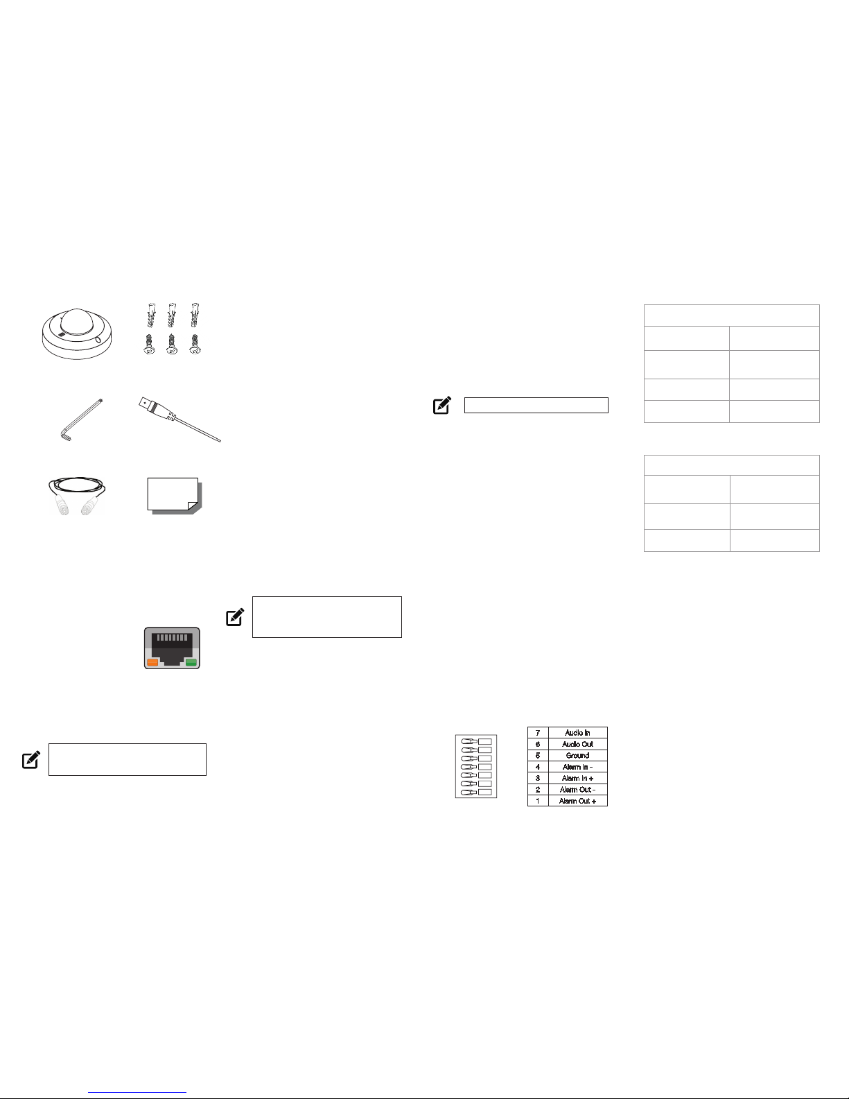
CONNECTIONS
1
1
3
8
2
4
5
6
7
1 RJ-45 - For network and PoE connections
2
Power (12vDC /
24vAC)
1 12vDC + 24vAC1
Power Connection
2 GND - 24vAC2
3 Reset Button -
Press the reset button with a proper tool for at least 20
seconds to return the camera to factory defaults
4 Alarm & Audio I / O
1 Alarm Out +
Alarm connection
2 Alarm Out -
3 Alarm In +
4 Alarm In -
5 GND
Ground connection
6 Audio Out
Two-way audio transmission
7 Audio In
5 BNC - For analog video output
6 Built-in Microphone - Audio In
7 Speaker - Audio Out
8 microSD Card Slot -
Insert the microSD card into the slot to store videos
and snapshots
1
7
Page 2
CONTENTS
ETHERNET CABLE
CONNECTIONS
Connect a network cable to the camera
using the RJ45 input and connect the
other end of the cable to your network
switch or recorder.
Check the status
of the network
connection by looking
at the link indicator
and activity indicator
LEDs. If the LEDs are not lit check your
network connection. The green link LED
indicates a network connection and the
orange activity LED flashes to indicate
network activity.
NOTE If you are connecting the camera directly
to a recorder, a crossover cable is
necessary for most configurations.
OE-C6123-W
Dome Camera
PRODUCT FEATURES
Camera
Maximum Resolution
3MP
Frame Rate at
Maximum Resolution
25/30 IPS @ H.264 (3MP)
Total Streams
Up to 3 simultaneous
streams
ONVIF
ONVIF Profile S
Compliant
Environmental and Power
Power
Consumption
3.64W
(+0.6W w/SD card)
Input Voltage
12vDC / 24vAC / PoE
Operating
Temperature
-4 ~ 131 °F (-20 ~ 55 °C)
Quick Start
Guide
Security Torx
Tool
CONNECTING TO THE
IP CAMERA
To access the camera setup menu, you
need to install the OpenEye Network
Camera Manager on a PC on the same
network. To install the OpenEye Network
Camera Manager application on your PC,
download the program from Openeye.net,
and follow the prompts.
1. Open Network Camera Manager,
and click Find Devices.
2. Locate your camera on the Network
Camera Manager list.
3. To open the viewer software in
your web browser, double-click the
camera, and then click Browse.
The first time you connect to the camera
you will be automatically prompted to
install a plugin to view live video.
Default Username and Password
The username and password are case
sensitive. It is strongly recommended
that the password be changed after
the initial setup to prevent unauthorized
access. Any password change will need
to be applied to your recorder also.
Username: admin
Password: 1234
POWER
This camera is compatible with Power
over Ethernet (PoE). Make sure the Power
Sourcing Equipment (PSE) is in use in the
network.
ASSIGNING AN
IP ADDRESS
OpenEye IP cameras default to DHCP.
This automatically assigns an IP address
to the camera. If no DHCP is available,
the camera will default to a static IP of
192.168.0.250 after four minutes. To
modify the IP address, use the OpenEye
Network Camera Manager.
1. Open the Network Camera
Manager application.
2. Click Find Devices, and
then double-click the desired
camera.
3. Click Network Setup.
4. Select Static IP and type the new
IP address and other network
information in the appropriate
boxes.
- or -
Select DHCP.
5. Click Apply.
6. Click OK to acknowledge the
change.
NOTE ActiveX controller is for use with
Internet Explorer only. Use the
QuickTime plugin with other web
browsers.
TIP Static IP is the recommended default.
Self-Tapping
Screws (x3) &
Plastic Anchors (x3)
ALARM I/O
ARRANGEMENT
The camera supports one alarm
input and one relay output for alarm
application.
See the Connections diagram for the
Alarm I/O location and orientation.
1
2
4
3
5
6
7
Power Cable
BNC Cable
7 Audio In
6 Audio Out
5 Ground
4 Alarm In -
3 Alarm In +
2 Alarm Out -
1 Alarm Out +
 Loading...