

Page 1

Network Video Recorder
Hardware Manual
N-Series
N1
OE4-N1U32
OE4-N1U16
OE4-N1U08
N3
OE4-N3U32
OE4-N3U16
OE4-N3U08
www.openeye.net
Page 2

ii
Page 3

OpenEye® N - Series NVR
Hardware Manual
Manual Edition 29205AC – AUGUST 2010
©2000-2010, OPENEYE
All Rights reserved.
No part of this document may be reproduced by any means, electronic or mechanical, for any purpose, except as expressed in the Software
License Agreement. OPENEYE shall not be liable for technical or editorial errors or omissions contained herein. The information in this
document is subject to change without notice.
The information in this publication is provided “as is” without warranty of any kind. The entire risk arising out of the use of this information
remains with recipient. In no event shall OPENEYE be liable for any direct, consequential, incidental, special, punitive, or other damages
whatsoever (including without limitation, damages for loss of business profits, business interruption or loss of business information), even if
OPENEYE has been advised of the possibility of such damages or whether in an action, contract or tort, including negligence.
This software and documentation are copyrighted. All other rights, including ownership of the software, are reserved to OPENEYE. OPENEYE,
OpenEye, HDDR, and High Definition Digital Recorder are registered trademarks of OPENEYE in the United States and elsewhere; Windows,
and Windows XP Embedded are registered trademarks of Microsoft Corporation. All other brand and product nam es are tradem ark s or
registered trademarks of the respective owners.
The following words and symbols mark special messages throughout this guide:
Warning Text set off in this manner indicates that failure to follow directions
could result in bodily harm or loss of life.
Caution Text set off in this manner indicates that failure to follow directions
could result in damage to equipment or loss of information.
OPENEYE
Liberty Lake WA • USA
29205AB iii
Page 4

IMPORTANT SAFEGUARDS
1. Read Owner’s Manual – After unpacking this product, read the owner’s manual carefully, and follow all the operating and other
instruction
2. Power Sources – This product should be operated only from the type of power source indicated on the label. If not sure of the
type of power supply to your home or business, consult product dealer or local power company
3. Ventilation – Slots and openings in the cabinet are provided for ventilation and to ensure reliable operation of the product and to
protect it from overheating, and these openings must not be blocked or covered. The product should not be placed in a built-in
installation such as a bookcase or rack unless proper ventilation is provided or the manufacturer’s instructions have been adhered
to.
4. Heat – The product should be situated away from heat sources such as radiators, heat registers, stoves, or other products that
produce heat.
5. Water and Moisture – Do not use this product near water. Do not exceed the humidity specifications for the product as detailed in
the Appendix section in this manual
6. Cleaning – Unplug this product from the wall outlet before cleaning. Do not use liquid cleaners or aerosol cleaners. Use a damp
cloth for cleaning.
7. Power Cord Protection – Power-supply cords should be routed so that they are not likely to be walked on or pinched by items
placed against them, paying particular attention to cords at plugs, convenience receptacles, and the point where they exit from the
product.
8. Overloading – Do not overload wall outlets, extension cords, or integral convenience receptacles as this can result in a risk of fire
or electrical shock.
9. Lightning – For added protection for this product during storm, or when it is left unattended and unused for long periods, unplug it
from the wall outlet. This will prevent damage to the product due to lightning and power line surges.
10. Object and Liquid Entry Points – Never insert foreign objects into the DVR, other than the media types approved by OpenEye,
as they may touch dangerous voltage points or short-out parts that could result in a fire or electrical shock. Never spill liquid of any
kind on the product.
11. Accessories – Do not place this product on an unstable cart, stand, tripod, bracket, or table. The product may fall, causing serious
personal injury and serious damage to the product.
12. Disc Tray – Keep fingers well clear of the disc tray as it is closing. Neglecting to do so may cause serious personal injury.
13. Burden – Do not place a heavy object on or step on the product. The object may fall, causing serious personal injury and serious
damage to the product.
14. Disc – Do not use a cracked, deformed, or repaired disc. These discs are easily broken and may cause serious personal injury
and product malfunction.
iv
Page 5

IMPORTANT SAFEGUARDS, continued
15. Damage Requiring Service – Unplug the unit from the outlet and refer servicing to qualified service personnel under the following
conditions:
When the power-supply cord or plug is damaged.
If liquid has been spilled, or objects have fallen into the unit.
If the unit has been exposed to rain or water.
If the unit does not operate normally by following the operating instructions. Adjust only those controls that are covered by the
operating instructions as an improper adjustment of other controls may result in damage and will often require extensive work by a
qualified technician to restore the unit to its normal operation.
If the unit has been dropped or the enclosure has been damaged.
When the unit exhibits a distinct change in performance – this indicates a need for service.
16. Servicing – Do not attempt to service this product as opening or removing covers may expose the user to dangerous voltage or
other hazards. Refer all servicing to qualified personnel.
17. Replacement Parts – When replacement parts are required, be sure the service technician has used replacement parts specified
by the manufacturer or have the same characteristics as the original part. Unauthorized substitutions may result in fire, electric
shock or other hazards.
18. Safety Check – Upon completion of any service or repairs to this unit, ask the service technician to perform safety checks to
determine that the unit is in proper operating condition.
NOTES ON HANDLING
Please retain the original shipping carton and/or packing materials supplied with this product. To ensure the integrity of this product when
shipping or moving, repackage the unit as it was originally received from the manufacturer.
Do not use volatile liquids, such as aerosol spray, near this product. Do not leave rubber or plastic objects in contact with this product for
extended periods of time. Rubber or plastic objects left in contact with this product for extended periods of time will leave marks on the
finish.
The top and rear panels of the unit may become warm after long periods of use. This is not a malfunction.
NOTES ON LOCATING
Place this unit on a level surface. Do not use it on a shaky or unstable surface such as a wobbling table or inclined stand.
If this unit is placed next to a TV, radio, or VCR, the playback picture may become poor and the sound may be distorted. If this happens,
place the DVR away from the TV, radio, or VCR.
29205AB v
Page 6

NOTES ON CLEANING
Use a soft dry cloth for cleaning.
For stubborn dirt, soak the cloth in a weak detergent solution, wring well and wipe. Use a dry cloth to wipe it dry. Do not use any type of
solvent, such as thinner and benzene, as they may damage the surface of the DVR.
If using a chemical saturated cloth to clean the unit, follow that product’s instructions.
NOTES ON MAINTENANCE
This DVR is designed to last for long periods of time. To keep the DVR always operational we recommend regular inspection maintenance
(cleaning parts or replacement). For details, contact the nearest dealer.
NOTES ON MOISTURE CONDENSATION
Moisture condensation damages the DVR. Read the following information carefully.
Moisture condensation occurs during the following cases:
When this product is brought directly from a cool location to a warm location.
When this product is moved to a hot and humid location from a cool location.
When this product is moved to a cool and humid location from a warm location.
When this product is used in a room where the temperature fluctuates.
When this product is used near an air-conditioning unit vent
When this product is used in a humid location.
Do not use the DVR when moisture condensation may occur.
If the DVR is used in such a situation, it may damage discs and internal parts. Remove any CD discs, connect the power cord of the DVR to
the wall outlet, turn on the DVR, and leave it for two to three hours. After two to three hours, the DVR will warm up and evaporate any
moisture. Keep the DVR connected to the wall and moisture will seldom occur.
vi
Page 7
WARNING
TO REDUCE THE RISK OF ELECTRICAL SHOCK, DO NOT EXPOSE THIS APPLIANCE TO RAIN OR MOISTURE.
DANGEROUS HIGH VOLTAGES ARE PRESENT INSIDE THE ENCLOSURE.
DO NOT OPEN THE CABINET.
REFER SERVICING TO QUALIFIED PERSONNEL ONLY.
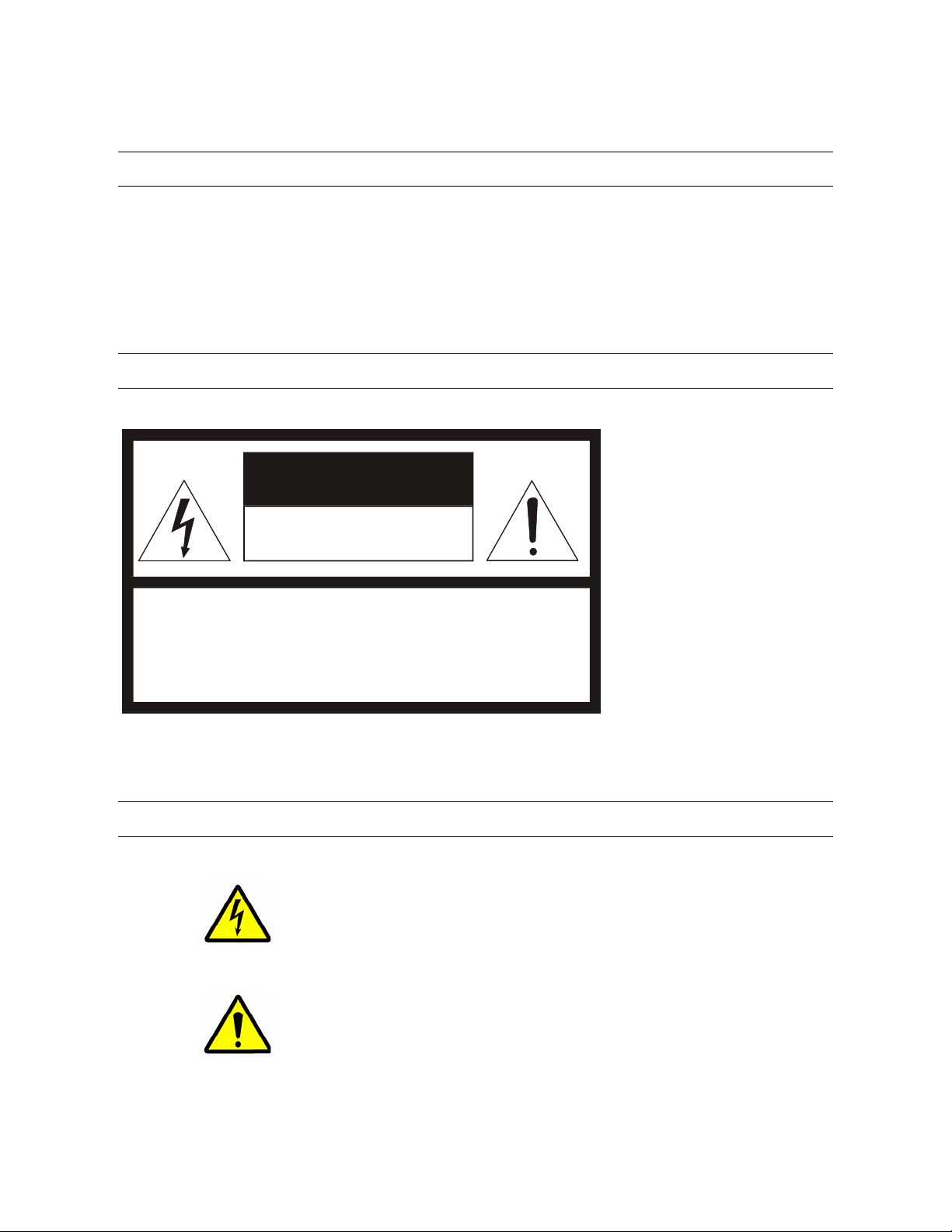
CAUTION
CAUTION
RISK OF ELECTRIC SHOCK
DO NOT OPEN
CAUTION: TO REDUCE THE RISK OF ELECTRIC SHOCK,
DO NOT REMOVE COVER ( O R BACK).
NO USER-SERVICEABLE PARTS INSIDE.
REFER SERVICING T O QUALIFIED SERVI CE PERSONNE L.
EXPLANATION OF GRAPHICAL SYMBOLS
The lightning flash with arrowhead symbol, within an equilateral triangle, is intended to alert the user to the
presence of un-insulated “dangerous voltage” within the product’s enclosure that may be of sufficient
magnitude to constitute a risk of electric shock to persons.
The exclamation point within an equilateral triangle is intended to alert the user to the presence of
important operating and maintenance (servicing) instruction in the literature accompanying the product.
29205AB vii
Page 8

RACK MOUNT INSTRUCTIONS
Elevated Operating Ambient – If installed in a closed or multi-unit rack assembly, the operating ambient temperature of the rack
environment may be greater than room ambient. Therefore, consideration should be given to installing the equipment in an environment
compatible with the maximum ambient temperature (Tma) specified by the manufacturer.
Reduced Air Flow – Installation of the equipment in a rack should be such that the amount of airflow required for safe operation of the
equipment is not compromised.
Mechanical Loading – Mounting of the equipment in the rack should be such that a hazardous condition is not achieved due to uneven
mechanical loading.
Circuit Overloading – Consideration should be given to the connection of the equipment to the supply circuit and the effect that
overloading of the circuits might have on over current protection and supply wiring. Appropriate consideration of equipment nameplate
ratings should be used when addressing this concern.
Grounding – Grounding of rack-mounted equipment should be maintained. Particular attention should be given to supply connections other
than direct connections to the branch circuit (e.g. use of power strips).
FCC STATEMENT
This equipment has been tested and found to comply with the limits for a Class A digital device, pursuant to Part 15 of the FCC Rules.
These limits are designed to provide reasonable protection against harmful interference when the equipment is operated in a commercial
environment. This equipment generates, uses, and can radiate radio frequency energy and, if not installed and used in accordance with the
instruction manual, may cause harmful interference to radio communications. Operation of this equipment in a residential area is likely to
cause harmful interference in which case the user will be required to correct the interference at his own expense.
UL NOTICE
Underwriters Laboratories Inc. has not tested the performance or reliability of the security or signaling aspects of this product. UL has only
tested for fire, shock and casualty hazards as outlined in UL’s Standard for Safety UL 60950-1. UL Certification does not cover the
performance or reliability of the security or signaling aspects if this product. UL MAKES NO REPRESENTATIONS, WARRANTIES OR
CERTIFICATIONS WHATSOEVER REGARDING THE PERFORMANCE OR RELIABILITY OF ANY SECURITY OR SIGNALING
RELATED FUNCTIONS OF THIS PRODUCT.
viii
Page 9

CE NOTICE
This product is in conformity with the following European Directives:
ELECTROMAGNETIC COMPATIBILITY DIRECTIVE, 89/336/EEC
(as amended by 92/31/EECand by Article 5 of 93/68/EEC)
per the provisions of:
EN 55022:1994 EN 55024:1998 EN 61000-4-4:1995
EN 61000-3-2:1995 CISPR 24:1997 EN 61000-4-5:1995
EN 61000-3-3:1995 EN 61000-4-2:1995 EN 61000-4-6:1995
CISPR 22:1997 EN 61000-4-3:2002 EN 61000-4-11:1994
LOW VOLTAGE DIRECTIVE, 73/23/EEC
(as amended by Article 13 of 93/68/EEC)
per the provisions of:
EN 60950-1: 2001
Standard Warranty
OpenEye warrants all new products to be free from defects in workmanship a nd material under n ormal use for a period of two years af ter
the date of purchase. Any defective product that fall s under this warranty will, at OpenEye's discretion, be repaired or replaced at no
additional charge. OpenEye may elect to replace defective products wi th new or factory reconditioned pr oducts of equal or great er value.
Repairs made necessary by reason of misuse, alteration, normal wear, or accident are not covered under this warranty.
Exceptions to this are listed below:
• Three Years on all Digital Recorders
• Three years on all fixed cameras
All products shall be covered by a one year advance replacement warranty*.
OpenEye will warrant all otherwise out of warranty replacement parts and repairs for 90 days from the date of OpenEye shipment.
The above warranty is the sole warranty made by OpenEye and is in lieu of all other warranties by OpenEye express and implied, including
without limitation the warranties of merchantability and fitness for a particular purpose. Under no circumstances will OpenEye be liable for
any consequential, incidental, special or exemplary damages arising out of or connected with the sale, delivery, use or performance of the
product, even if OpenEye is apprised of the likelihood of such damages occurring. In no event shall OpenEye liability exceed the purchase
price of the product.
This warranty gives you specific legal rights and you may also have other rights which vary from state to state or country to country.
*Requires corresponding security deposit. Advanced Replacement limited to components only outside of the USA and Canada.
For the most up to date information visit www.openeye.net
29205AB ix
Page 10

Table of Contents
PREFACE .................................................................................................................................................................... 11
ABOUT THIS GUIDE .............................................................................................................................................. 11
TECHNICIAN NOTES ............................................................................................................................................. 11
INTRODUCTION .......................................................................................................................................................... 13
PRODUCT DESCRIPTION ..................................................................................................................................... 13
FEATURES ............................................................................................................................................................. 14
CONTROLS AND CONNECTIONS ............................................................................................................................. 15
FRONT PANEL CONTROLS .................................................................................................................................. 15
N3 Front Panel ................................................................................................................................................... 15
N1 Front Panel ................................................................................................................................................... 15
REAR PANEL CONNECTORS ............................................................................................................................... 16
N3 Rear Panel .................................................................................................................................................... 16
N1 Rear Panel .................................................................................................................................................... 16
GETTING STARTED ................................................................................................................................................... 17
IDENTIFYING INCLUDED COMPONENTS ............................................................................................................ 17
OPTIONAL COMPONENTS .................................................................................................................................... 18
KEYBOARD SETUP ............................................................................................................................................... 19
MOUSE SETUP ...................................................................................................................................................... 19
MONITOR SETUP .................................................................................................................................................. 20
POWER SETUP ...................................................................................................................................................... 20
N1 RACKMOUNT KIT INSTALLATION ................................................................................................................... 21
Identifying the Sections of the Rack Rails........................................................................................................... 21
Installing the Inner Rails ..................................................................................................................................... 21
Installing the Outer Rails .................................................................................................................................... 22
Installing the N1 into the Rack ............................................................................................................................ 23
Installing the N1 into a Telco Rack ..................................................................................................................... 24
TURNING ON THE NVR ......................................................................................................................................... 25
TURNING OFF THE NVR ....................................................................................................................................... 25
TECHNICAL SPECIFICATIONS ................................................................................................................................. 26
SYSTEM SPECIFICATIONS ................................................................................................................................... 26
x
Page 11

PREFACE
ABOUT THIS GUIDE
This manual is a setup and maintenance guide that can be used for reference when setting up the N1 and N3 NVR and for
troubleshooting when a problem occurs. Only authorized personnel should attempt to repair the NVR.
OpenEye reserves the right to make changes to the NVRs represented by this manual without notice.
The following text and symbols mark special messages throughout this guide:
Note Text set off in this manner indicates topics of interests that can help the user understand the product better.
Tip Text set off in this manner indicates topics and points of interests that can be helpful when using or settings up the NVR.
TECHNICIAN NOTES
Warning Only authorized technicians trained by OpenEye should attempt to repair this NVR. All troubleshooting and
repair procedures that may be shown are for reference and minor repair only. Because of the complexity of the individual
components and subassemblies, no one should attempt to make repairs at the component level or to make modifications
to any printed wiring board. Improper repairs can create a safety hazard. And any indications of component replacement
or printed wiring board modifications may void any warranty
Warning To reduce the risk of electrical shock or damage to the equipment:
• Do not disable the power grounding plug. The grounding plug is an important safety feature.
• Plug the power cord into a grounded (earthed) electrical outlet that is easily accessible at all times.
• Disconnect the power from the computer by unplugging the power cord either from the electrical outlet or the
computer.
Caution To properly ventilate your system, you must provide at least 3 inches (7.6 cm) of clearance at the front and
back of the NVR.
29205AC 11
Page 12

12
Page 13

INTRODUCTION
PRODUCT DESCRIPTION
The OpenEye N-Series NVR is a server that performs as a High Definition Digital Recorder. By utilizing the many features of a
computer, including processing power, storage capacity, graphics compression, and security features, the N-Series is more powerful
than the analog recorders of the past.
The OpenEye NVR server software comes pre-configured for fast and seamless integration within your existing IT infrastructure.
Designed around Microsoft
Accordingly, your security investment has never been easier to maintain. Multiple users may simultaneously connect through any
network connection for instantaneous live viewing, digital search, and off site video storage. Users can also connect remotely through
DSL, Cable Modems, or ISDN. This powerful software enables users to establish recording schedules, create motion detection zones,
use PTZ controls, and configure alarm inputs and outputs for each of the system's cameras. With the latest advancements in the DVR
Server Software, searching and indexing your video archive has never been easier. Video can now be found, viewed, and exported in
a number of file formats with just a few clicks.
The OpenEye NVR is a high performance security product ready to meet today’s security demands.
®
Windows XP Embedded, the server software offers unparalleled stability, security, and ease of use.
29205AC 13
Page 14

FEATURES
OpenEye® NVRs include the following features:
• Optimized and Designed for Microsoft® Windows XP Embedded®
• Remote System Operation & Configuration
• Supports Multiple Simultaneous Remote Connections
• Connect up to 32 Network Video Devices
• PAN / TILT / ZOOM Controls
• Simultaneous Video Search, Playback and Backup
• Video Indexes for Easy Searching
• Multiple Levels of Security Access
• Optional POS and ATM Support
• 1 DVI-D Output & 1 SVGA Output (N3)
• 2 DVI-I Outputs & 2 SVGA adapters (N1)
• S Video Output (N3 only)
• High Performance, Durable, Rack Mount Case
• Output the Video to a NTSC/PAL Display
• Digital Signature Support
• Continuous, Motion Detection, Alarm, Pre-Alarm, and Scheduled Recording Modes
• Hardware Watchdog
• Camera Dependant Recording Resolutions
14
Page 15

CONTROLS AND CONNECTIONS
FRONT PANEL CONTROLS
The front panel of the NVR contains the devices that will be commonly used for data removal, retrieval, and backup replacement. The
most common components and buttons are shown below:
N3 FRONT PANEL
USB Ports
DVD±RW Drive
Power Switch
Hard Drive Activity LED
Power LED
Cooling Fan Intakes
N1 FRONT PANEL
Cooling Fan Intakes
Removable HDD Bays
DVD±RW Drive
Power Switch
Power LED
Hard Drive Activity LED
29205AC 15
Page 16

t
t
t
REAR PANEL CONNECTORS
The rear panel of the NVR contains the connectors used to attach display monitors and network cables to the NVR. The following
diagram outlines the location and description of each connector:
N3 REAR PANEL
AC Power Connector
PS/2 Mouse Inpu
PS/2 Keyboard Input
DVI-D
N1 REAR PANEL
SVGA Output
Fire Wire
RJ-45 Network Jack
USB Ports
Cooling Fan
Audio
• Line In – line level
• Speaker Out
• Microphone In – not used
AC Power Connector
PS/2 Mouse Inpu
PS/2 Keyboard Inpu
Serial Port
USB Ports
(disabled)
RJ-45 Network Jack
Video Cable Adapter
16
Page 17

GETTING STARTED
IDENTIFYING INCLUDED COMPONENTS
OpenEye NVRs come with a mouse, keyboard and selected software and cables. Identify the following components to make sure
everything has been properly included with the new NVR. If any of the following items are missing, contact the dealer to arrange a
replacement.
Power Adapter Mouse Keyboard
NVR Key (N3 only) Repair Disc/ Software Disc
Dual DVI-I Video Cable (N1 only) DVI to VGA adapter x2 (N1 only)
29205AC 17
Page 18

OPTIONAL COMPONENTS
To fully utilize the NVR’s potential; several optional OpenEye components are listed below. Contact your dealer for more information.
1 USB External Hard Drive
An easy way to extract large amounts of Video Data from the NVR is to use a USB External Hard Drive. This drive connects to the
USB port on the NVR and can be attached to any computer with an USB port.
2 Fiber Network Interface Adapter
A Fiber Network Adapter is used in enterprise network environments where large amounts of data are transferred across the LAN. If
large groups of people are logging in remotely across the LAN, the Fiber adapter will speed the data transfer.
3 Granite Rack (External Raid Storage Unit)
The Granite Rack external storage solution offers the potential of over 36 terabytes of data storage. 1U and 3U models are available.
The addition of extended storage to a NVR will allow longer periods of recording without overwriting the previously recorded data.
18
Page 19

KEYBOARD SETUP
To attach the keyboard to the NVR, plug the end of the Keyboard into the keyboard PS/2 Port located on the back of the machine. The
keyboard PS/2 Port can be identified by the purple color. Refer to the Rear Panel Connectors diagram for more information.
MOUSE SETUP
To attach the mouse to the NVR, plug the end of the mouse into the mouse PS/2 Port located on the back of the machine. The mouse
PS/2 Port can be identified by the green color.
The mouse uses a cursor called a pointer. Pointers come in many different shapes but are most commonly shaped like an arrow.
The mouse has two buttons: a left button and a right button. Quickly pressing and releasing one of these buttons is called clicking.
Sometimes you will need to double-click – or click the same button twice quickly.
In this manual:
Click means to position the mouse cursor over an item and to single click the left button.
Right click means to position the mouse cursor over an item and to single click the right button.
Double-click means to position the mouse cursor over an item and to click the left button twice.
Select means to position the mouse cursor over a radio button, checkbox, or list item and click on it.
The scroll wheel in between the two buttons is used for added navigation functionality. By moving the wheel with index finger
(scrolling), quickly move through multiple pages, lines, or windows. The wheel may also function as a third button allowing the user to
quickly click or double-click an icon or a selected item
Scroll Button / Third Button
Right Button
Left Button
29205AC 19
Page 20

MONITOR SETUP
The NVR may have one or both of the following connections available for monitors which can be used individually or in tandem.
DVI Output To TV / Digital Monitor
SVGA Output To VGA Monitor
Attach the monitor or monitors to the rear of the NVR using the cable supplied by the monitor manufacturer. Refer to the monitor
manual for detailed information on how to setup and use it.
Note The monitor must be capable of displaying a screen resolution of 1024 x 768 and at least 32 Bit color.
POWER SETUP
WARNING:
To reduce the risk of electrical shock or damage to the equipment:
Do not disable the power grounding plug.
The grounding plug is an important safety feature.
If the electrical plug you are using does not have a ground plug receptacle contact a licensed
electrician to have it replaced with a grounded electrical outlet.
Plug the power cord into a grounded (earthed) electrical outlet that is easily accessible at all times.
Disconnect the power from the computer by unplugging the power cord either from the electrical
outlet or the computer.
20
Page 21

N1 RACKMOUNT KIT INSTALLATION
This section provides information on installing the OpenEye 1U NVR into a rack unit with the rack rails provided. There are a variety of
rack units on the market which may mean the assembly procedure will differ slightly. You should refer to the installation instructions
that came with the rack unit you are using.
IDENTIFYING THE SECTIONS OF THE RACK RAILS
You should have received two rack rail assemblies in the rack mounting kit. Each assembly consists of two sections: an inner fixed
chassis rail that secures directly to the server chassis and an outer fixed rack rail that secures directly to the rack itself (see Figure 1-
1). Two pairs of short brackets to be used on the front side of the outer rails are also included.
Figure 1-1. Identifying the Sections of the Rack Rails (right side rail shown)
INSTALLING THE INNER RAILS
Both the left and right side inner rails come pre-attached to the chassis.
29205AC 21
Page 22

INSTALLING THE OUTER RAILS
Start by measuring the distance from the front rail to the rear rail of the rack. Attach a short bracket to the front side of the right outer
rail and a long bracket to the rear side of the right outer rail. Adjust both the short and long brackets to the proper distance so that the
rail can fit snugly into the rack. Secure the short bracket to the front side of the outer rail with two screws and the long bracket to the
rear side of the outer rail with three screws. Repeat these steps for the left outer rail.
Locking Tabs: Both chassis rails have a locking tab, which serves two functions. The first is to lock the server into place when
installed and pushed fully into the rack, which is its normal position. Secondly, these tabs also lock the server in place when fully
extended from the rack. This prevents the server from coming completely out of the rack when you pull it out for servicing.
Figure 1-2. Installing the Rack Rails
22
Page 23

INSTALLING THE N1 INTO THE RACK
You should now have rails attached to both the chassis and the rack unit. The next step is to install the server into the rack. Line up
the rear of the chassis rails with the front of the rack rails and slide the chassis rails into the rack rails, keeping the pres s ure ev en on
both sides (you may have to depress the locking tabs when inserting). See Figure 1-3.
When the server has been pushed completely into the rack, you should hear the locking tabs "click".
Figure 2-3. Installing the N1 into a Rack
29205AC 23
Page 24

INSTALLING THE N1 INTO A TELCO RACK
To install the Openeye 1U NVR into a Telco type rack, use two L-shaped brackets on either side of the chassis (four total). First,
determine how far forward the server will extend out the front of the rack. Larger chassis should be positioned to balance the weight
between front and back. If a bezel is included on your NVR, remove it. Then attach the two front brackets to each side of the chassis,
then the two rear brackets positioned with just enough space to accommodate the width of the Telco rack. Finish by sliding the chassis
into the rack and tightening the brackets to the rack.
Figure 1-4. Installing the N1 into a Telco Rack
24
Page 25

TURNING ON THE NVR
1. Turn on the monitor and any external peripherals (ex. Printers, External Storage Devices, etc.) connected to the NVR.
2. Turn on the secondary power switch located on the rear of the NVR.
3. Turn on the main power switch located on the front of the NVR.
4. The NVR will run a series of self-tests. After two or three minutes, a series of messages may be displayed as the various
hardware and software subsystems are activated. Under normal circumstances, users should not be asked to respond to these
messages. If asked to respond to the messages (adding a Printer, Monitor, etc for the first time) follow the instructions carefully.
5. Startup is complete when OpenEye® NVR software is finished loading and displays the main menu screen.
TURNING OFF THE NVR
1. Click the Exit Button on the main menu screen of the NVR software.
2. Select Power Off from the drop down menu, which appears in the Power Off prompt, and click OK.
The NVR may take several minutes to shut down completely.
Caution Always be sure to follow the proper procedures when turning off the power to the NVR. NEVER disconnect the power to the
NVR while it is still running or in the process of shutting down. Doing so can cause data loss, file corruption, system
instability and hardware failure.
29205AC 25
Page 26

TECHNICAL SPECIFICATIONS
SYSTEM SPECIFICATIONS
N3 N1
Camera Channels 8 16 32 8 16 32
Max PPS Per Channel 30 30
Recording Rate Dependant on the resolutions the network video device supports
Live Display Rate 4 Channel Local Live / All Available Channels Displayed in Remote or RADIUS Software
Audio Channels Up to 16, dependant on network video device capabilities
Video Outputs 1 DVI-D, 1 SVGA 2 DVI-I w/ 2 SVGA adapters
Image Compression Camera Specific
Video Signal Loss Detection Yes
Motion Detection Up to 15 Regions Per Channel / Adjustable Sensitivity
Remote Operation LAN / WAN – TCP/IP
Remote Software Setup Access, Search / Compatible with Microsoft Windows XP, Vista
PAN / TILT / ZOOM Yes, Via IP Protocols
Recording Mode Continuous, Motion Detection
Playback Search Multiple Enhanced Search Capabilities
Backup USB, DVD RW, Network
Digital Signature Support Yes, AVI and JPEG
Dynamic DNS Free for Life of Product
Operating System Microsoft® Windows® XP Embedded
Storage (Size) 500 GB Standard / 1TB / 2TB / 4TB 500 GB Standard / 1TB / 2TB / 4TB / 6TB / 8TB
External Storage Options Ultra-320 SCSI Interface (Optional)
Dimensions L: 19.5” x W: 17.2” x H: 5.8”
L: 495mm x W: 437mm x H: 148mm
Warranty 3 Years / 1 Year Advance Replacement
L: 25.6” x W: 17.2” x H: 1.7”
L: 650mm x W: 437mm x H: 43mm
26
Page 27

www.openeye.net
1-888-542-1103
© 2010 OpenEye
All rights reserved. No part of this publication may be reproduced by any means without written
permission from OpenEye. The information in this publication is believed to be accurate in all respects.
However, OpenEye cannot assume responsibility for any consequences resulting from the use thereof.
The information contained herein is subject to change without notice. Revisions or new editions to this
publication may be issued to incorporate such changes.
29205AC 27
 Loading...