

Page 1
Network Video Recorder
User Manual
N-Series
N4
OE5-N4U64
OE5-N4U32
OE5-N4U16
N3
OE5-N3U32
OE5-N3U16
OE5-N3U08
N2
OE5-N2U64
OE5-N2U32
OE5-N2U16
OE5-N2U08
NM
OE5-NM04
www.openeye.net
Page 2

2
Page 3

OpenEye® N-Series NVR
Operations Manual
Manual Edition 30777AC – MAY 2012
©2000-2012, OPENEYE
All Rights Reserved
No part of this document may be reproduced by any means, electronic or mechanical, for any purpose, except as
expressed in the Software License Agreement. OPENEYE shall not be liable for technical or editorial errors or
omissions contained herein. The information in this document is subject to change without notice.
The information in this publication is provided “as is” without warranty of any kind. The entire risk arising out of the
use of this information remains with recipient. In no event shall OPENEYE be liable for any direct, consequential,
incidental, special, punitive, or other damages whatsoever (including without limitation, damages for loss of business
profits, business interruption or loss of business information), even if OPENEYE has been advised of the possibility of
such damages or whether in an action, contract or tort, in clu ding neg lige nc e.
This software and documentation are copyrighted. All other rights, including ownership of the software, are reserved
to OPENEYE. OPENEYE, OpenEye, HDDR, and High Definition Digital Recorder are registered trademarks of
OPENEYE in the United States and elsewhere; Windows, and Windows XP Embedded are registered trademarks of
Microsoft Corporation. All other brand and product names are trademarks or registered trademarks of the respective
owners.
The following words and symbols mark special messages throughout this guide:
Note Text set off in this manner indicates information that is necessary for proper operation of the
product.
Tip Text set off in this manner indicates information that may be helpful.
Caution Text set off in this manner indicates that failure to follow directions could result in damage
to equipment or loss of information.
OPENEYE
Liberty Lake, WA ● U.S.A.
30777AC 3
Page 4

IMPORTANT SAF EGUARDS
1. Read Owner’s Manual – After unpacking this product, read the owner’s manual carefully, and follow all the
operating and other instruction
2. Power Sources – This product should be operated only from the type of power source indicated on the label. If
not sure of the type of power supply to your home or business, consult product dealer or local power company
3. Ventilation – Slots and openings in the cabinet are provided for ventilation and to ensure reliable operation of
the product and to protect it from overheating, and these openings must not be blocked or covered. The product
should not be placed in a built-in installation such as a bookcase or rack unless proper ventilation is provided or
the manufacturer’s instructions have been adhered to.
4. Heat – The product should be situated away from heat sources such as radiators, heat registers, stoves, or other
products that produce heat.
5. Water and Moisture – Do not use this product near water.
6. Cleaning – Unplug this product from the wall outlet before cl eanin g. Do not use liquid cleaners or aerosol
cleaners. Use a damp cloth for cleaning.
7. Power Cord Protection – Power-supply cords should be routed so that they are not likely to be walked on or
pinched by items placed against them, paying particular attention to cords at plugs, convenience receptacles,
and the point where they exit from the product.
8. Overloading – Do not overload wall outlets, extension cords, or integral convenience receptacles as this can
result in a risk of fire or electrical shock.
9. Lightning – For added protection for this product during storm, or when it is left unattended and unused for long
periods, unplug it from the wall outlet. This will prevent damage to the product due to lightning and power line
surges.
10. Object and Liquid Entry Points – Never insert foreign objects into the NVR, other than the media types
approved by OpenEye, as they may touch dangerous voltage points or short-out parts that could result in a fire
or electrical shock. Never spill liquid of any kind on the product.
11. Accessories – Do not place this product on an unstable cart, stand, tripod, bracket, or table. The product may
fall, causing serious personal injury and serious damage to the product.
12. Disc Tray – Keep fingers well clear of the disc tray as it is closing. Neglecting to do so may cause serious
personal injury.
13. Burden – Do not place a heavy object on or step on the product. The object may fall, causing serious personal
injury and serious damage to the product.
14. Disc – Do not use a cracked, deformed, or repaired disc. These discs are easily broken and may cause serious
personal injury and product malfuncti on.
15. Damage Requiring Service – Unplug the unit from the outlet and refer servicing to qualified service personnel
under the following conditions:
• When the power-supply cord or plug is damaged.
• If liquid has been spilled, or objects have fallen into the unit.
• If the unit has been exposed to rain or water.
• If the unit does not operate normally by following the operating instructions. Adjust only those controls that
are covered by the operating instructions as an improper adjustment of other controls may result in damage
and will often require extensive work by a qualified technician to restore the unit to its normal operation.
• If the unit has been dropped or the enclosure has been damaged.
• When the unit exhibits a distinct change in performance – this indicates a need for service.
16. Servicing – Do not attempt to service this product as opening or removing covers may expose the user to
dangerous voltage or other hazards. Refer all servicing to qualified personnel.
17. Replacement Parts – When replacement parts are required, be sure the service technician has used
replacement parts specified by the manufacturer or have the same characteristics as the original part.
Unauthorized substitutions may result in fire, electric shock or other hazards.
18. Safety Check – Upon completion of any service or repairs to this unit, ask the service technician to perform
safety checks to determine that the unit is in proper operating condition.
4
Page 5

BATTERY EXPLOSION CAUTION STATEMENT
CAUTION: Risk of Explosion if Battery is replaced by an Incorrect Type.
Dispose of Used Batteries According to the Instructions.
NOTES ON HANDLING
Please retain the original shipping carton and/or packing materials supplied with this product. To ensure the integrity
of this product when shipping or moving, repackage the unit as it was originally received from the manufacturer.
Do not use volatile liquids, such as aerosol spray, near this product. Do not leave rubber or plastic objects in contact
with this product for extended periods of time. Rubber or plastic objects left in contact with this product for extended
periods of time will leave marks on the finish.
The top and rear panels of the unit may become warm after long periods of use. This is not a malfunction.
NOTES ON LOCATING
Place this unit on a level surface. Do not use it on a shaky or unstable surface such as a wobbling table or inclined
stand. If this unit is placed next to a TV, radio, or VCR, the playback picture may become poor and the sound may be
distorted. If this happens, place the NVR away from the TV, radio, or VCR.
NOTES ON CLEANING
Use a soft dry cloth for cleaning.
For stubborn dirt, soak the cloth in a weak detergent solution, wring well and wipe. Use a dry cloth to wipe it dry. Do
not use any type of solvent, such as thinner and benzene, as they may damage the surface of the NVR.
If using a chemical saturated cloth to clean the unit, follow that product’s instructions.
NOTES ON MAINTENANCE
This NVR is designed to last for long periods of time. To keep the NVR always operational we recommend regular
inspection maintenance (cleaning parts or replacement). For details, contact the nearest dealer.
30777AC 5
Page 6
NOTES ON MOISTURE CONDENSATION
CAUTION: TO REDUCE THE RISK OF ELECTRIC SHOCK,
DO NOT REMOVE COVER (OR BACK).
NO USER-SERVICEABLE PARTS INSIDE.
REFER SERVICI NG TO QUA LIF IED SERVICE PERSONNEL.
CAUTION
RISK OF ELECTRI C SHOCK
DO NOT OPEN
Moisture condensation damages the NVR. Read the following information carefully. Moisture conden sat ion oc curs
during the following cases:
• When this product is brought directly from a cool location to a warm location.
• When this product is moved to a hot and humid location from a cool location.
• When this product is moved to a cool and humid location from a warm location.
• When this product is used in a room where the temperature fluctuates.
• When this product is used near an air-condition ing unit vent
• When this product is used in a humid location.
Do not use the NVR when moisture condensation may occur.
If the NVR is used in such a situation, it may damage discs and internal parts. Remove any CD discs, connect the
power cord of the NVR to the wall outlet, turn on the NVR, and leave it for two to three hours. After two to three hours,
the NVR will warm up and evaporate any moisture. Keep the NVR connected to the wall and moisture will seldom
occur.
WARNING
TO REDUCE THE RISK OF ELECTRICAL SHOCK, DO NOT EXPOSE THIS APPLIANCE TO RAIN OR MOISTURE.
DANGEROUS HIGH VOLTAGES ARE PRESENT INSIDE THE ENCLOSURE.
DO NOT OPEN THE CABINET.
REFER SERVICING TO QUALIFIED PERSONNEL ONLY.
CAUTION
6
Page 7

RACK MOUNT INSTRUCTIONS
Elevated Operating Ambient – If installed in a closed or multi-unit rack assembly, the operating ambient
temperature of the rack environment may be greater than room ambient. Therefore, consideration should be given to
installing the equipment in an environment compatible with the maximum ambient temperature (Tma) specified by the
manufacturer.
Reduced Air Flow – Installation of the equipment in a rack should be such that the amount of airflow required for
safe operation of the equipment is not compromi sed.
Mechanical Loading – Mounting of the equipment in the rack should be such that a hazardous condition is not
achieved due to uneven mechanical loading.
Circuit Overloading – Consideration should be given to the connection of the equipment to the supply circuit and the
effect that overloading of the circuits might have on over current protection and supply wiring. Appropriate
consideration of equipment nameplate ratings should be used when addressing this concern.
Grounding – Grounding of rack-mounted equipment should be maintained. Particular attention should be given to
supply connections other than direct connections to the branch circuit (e.g. use of power strips).
FCC STATEMENT
INFORMATION TO THE USER: This equipment has been tested and found to comply with the limits for a Class B
digital device, pursuant to Part 15 of the FCC Rules. These limits are designed to provide reasonable protection
against harmful interference in a residential installation. This equipment generates, uses and can radiate radio
frequency energy and, if not installed and used in accordance with the instructions, may cause harmful interference to
radio communications. However, there is no guarantee that interference will not occur in a particular installation. If
this equipment does cause harmful interference to radio or television reception, which can be determined by turning
the equipment off and on, the user is encouraged to try to correct the interference by one or more of the following
measures:
• Reorient or relocate the receiving antenna.
• Increase the separation between the equipment and receiver.
• Connect the equipment into an outlet on a circuit different from that to which the receiver is connected.
• Consult the dealer or an experienced radio/TV technician for help.
USERS OF THE PRODUCT ARE RESPONSIBLE FOR CHECKING AND COMPLYING WITH ALL FEDERAL,
STATE, AND LOCAL LAWS AND STATUTES CONCERNING THE MONITORI NG AND RECORDING OF VIDEO
AND AUDIO SIGNALS. OPENEYE SHALL NOT BE HELD RESPONSIBLE FOR THE USE OF THIS PRODUCT IN
VIOLATION OF CURRENT LAWS AND STATUTES.
UL NOTICE
Underwriters Laboratories Inc. has not tested the performance or reliability of the security or signaling aspects of this
product. UL has only tested for fire, shock and casualty hazards as outlined in UL’s Standard for Safety UL 60950-1.
UL Certification does not cover the performance or reliability of the security or signaling aspects if this product. UL
MAKES NO REPRESENTATIONS, WARRANTIES OR CERTIFICATIONS WHATSOEVER REGARDING THE
PERFORMANCE OR RELIABILITY OF ANY SECURITY OR SIGNALING RELATED FUNCTIONS OF THIS
PRODUCT.
30777AC 7
Page 8

TABLE OF CONTENTS
TABLE OF CONTENTS ............................................................................................................................................ 8
PREFACE ............................................................................................................................................................... 13
About this Guide .............................................................................................................................. 13
Technician Notes ............................................................................................................................. 13
INTRODUCTION ..................................................................................................................................................... 14
Product Description ......................................................................................................................... 14
Features .......................................................................................................................................... 15
CONTROLS AND CONNECTIONS ........................................................................................................................ 16
Front Panel Controls and LEDs ....................................................................................................... 16
N2 Front Panel ......................................................................................................................... 16
N3 Front Panel ......................................................................................................................... 16
NM Front Panel ........................................................................................................................ 17
N4 Front Panel ......................................................................................................................... 17
Rear Panel Connectors ................................................................................................................... 18
N2 Rear Panel .......................................................................................................................... 18
N3 Rear Panel .......................................................................................................................... 18
NM Rear Panel ......................................................................................................................... 19
N4 Rear Panel .......................................................................................................................... 19
GETTING STARTED .............................................................................................................................................. 20
Identifying Included Components .................................................................................................... 20
Keyboard Setup ............................................................................................................................... 21
Mouse Setup ................................................................................................................................... 21
Monitor Setup .................................................................................................................................. 22
Power Setup .................................................................................................................................... 22
Hard Drive Array (N2 Only).............................................................................................................. 23
Removing a Hard Drive ............................................................................................................ 23
Inserting a Hard Drive .............................................................................................................. 23
N2 and N4 Rackmount Kit Installation ............................................................................................. 24
Preparing for Setup .................................................................... Error! Bookmark not defined.
Separating the Section of the Rack Rails ................................................................................. 24
Installing the Inner Rail Extensions .......................................................................................... 25
Installing the Outer Rack Rails ................................................................................................. 25
Installing the Recorder into a Rack ........................................................................................... 25
Turning On the NVR ........................................................................................................................ 26
Turning Off the NVR ........................................................................................................................ 26
NVR BASICS .......................................................................................................................................................... 27
Setting the Time and Date ............................................................................................................... 27
8
Page 9

Accessing the DVR Utility ................................................................................................................ 27
Exporting Settings .................................................................................................................... 27
Importing NVR Settings ............................................................................................................ 28
Display Screen ................................................................................................................................ 28
CPU Meter ................................................................................................................................ 29
Live Camera Options ................................................................................................................ 29
Camera View ................................................................................................................................... 30
Recording Status Indicator ....................................................................................................... 30
Special Recording .................................................................................................................... 30
Edit Live View Channels .................................................................................................................. 31
Screen Division Buttons .................................................................................................................. 31
Dual Monitor Camera Display Menu ......................................................................................... 32
Custom Live View Divisions ..................................................................................................... 32
SETUP OPTIONS ................................................................................................................................................... 33
Setup Overview ............................................................................................................................... 33
Setup Screen Overview ................................................................................................................... 33
Network Camera Setup ................................................................................................................... 34
Connecting a Network Device .................................................................................................. 34
Connecting Manually ......................................................................................................... 34
Connecting with Find Cameras ......................................................................................... 34
Assigning a Network Device to a Channel................................................................................ 35
Assigning Dual Streams ........................................................................................................... 36
Controlling a PTZ camera......................................................................................................... 37
Using the Graphical PTZ Controller .......................................................................................... 37
Assigning Audio Channels to a Network Device ....................................................................... 38
Camera Configuration .............................................................................................................. 39
Disable/Enable Live Video ................................................................................................ 39
Displaying More Columns ................................................................................................. 39
Accessing the Configuration Menu .................................................................................... 40
NVR Registration and Upgrade ................................................................................................ 40
Locating the System ID ..................................................................................................... 40
Obtaining the License Key ................................................................................................ 41
Unlocking the Upgrade ...................................................................................................... 41
Unlocking Additional Network Devices ..................................................................................... 41
Motion Setup ................................................................................................................................... 42
Create a Motion Area ............................................................................................................... 42
Enable Sabotage Detection ...................................................................................................... 43
General Setup ................................................................................................................................. 44
Voice Warning .......................................................................................................................... 45
Hybrid Sensor Setup ................................................................................................................ 45
Connecting to a Wide Screen Display ...................................................................................... 46
Connecting a Second Monitor .................................................................................................. 46
Setting Up Dual Monitor Preferences ................................................................................ 46
Volume ..................................................................................................................................... 47
30777AC 9
Page 10

Auto Sequence Setting ............................................................................................................. 47
Create Custom Auto Sequence ......................................................................................... 47
Schedule Setup ............................................................................................................................... 48
Recording Schedule ................................................................................................................. 48
Create a Recording Schedule ........................................................................................... 48
Sensor Schedule ...................................................................................................................... 49
Create a Sensor Schedule ................................................................................................ 49
Scheduling Alarm Events ......................................................................................................... 50
Emergency Agent Schedule ..................................................................................................... 50
Special Day Schedule .............................................................................................................. 51
Creating/Editing a ‘Special Day’ Schedule ........................................................................ 51
Deleting a ‘Special Day’ Schedule .................................................................................... 51
System Restart Setup .............................................................................................................. 52
Create System Restart Schedule ...................................................................................... 52
Network Setup ................................................................................................................................. 53
Administrative Setup ........................................................................................................................ 54
Disk Management .................................................................................................................... 54
Setting Up DDNS ..................................................................................................................... 55
Enable DDNS .................................................................................................................... 55
Set the IP Address ............................................................................................................ 55
User Management .................................................................................................................... 56
Add a New User ................................................................................................................ 56
User Rank ......................................................................................................................... 57
Changing the Administrator Password ..................................................................................... 57
Default Administrator Password ........................................................................................ 57
Log Management ..................................................................................................................... 58
Set Up Log Management Options ..................................................................................... 58
Status Check / Email ................................................................................................................ 59
General ............................................................................................................................. 59
Users ................................................................................................................................. 59
Storage Check .................................................................................................................. 60
Recording Data Check ...................................................................................................... 60
SMART Information ........................................................................................................... 60
SMART Alert ..................................................................................................................... 61
Alarm Event ....................................................................................................................... 61
ReportStar ......................................................................................................................... 62
Information....................................................................................................................................... 62
Instant Recording ............................................................................................................................ 63
Activate Instant Recording........................................................................................................ 63
Searching ‘Instant Recorded’ Video ......................................................................................... 63
SEARCH ................................................................................................................................................................. 64
Search Overview ............................................................................................................................. 64
Play Controls ............................................................................................................................ 64
Adjust the Brightness of an Image ............................................................................................ 65
10
Page 11

Zooming in on an Image ........................................................................................................... 65
Zooming in on a Portion of an Image ....................................................................................... 65
Open Video from a Saved Location .......................................................................................... 65
Time Sync ................................................................................................................................ 65
Clean Image ............................................................................................................................. 65
Performing a Basic Search .............................................................................................................. 66
Printing an Image ............................................................................................................................ 66
Daylight SAVIng Time ..................................................................................................................... 66
Save to JPG or AVI ......................................................................................................................... 67
Bookmarks ............................................................................................................................... 68
Modify Bookmarks ............................................................................................................. 68
Clip Backup .............................................................................................................................. 69
Single Clip Backup Using Bookmark Data ........................................................................ 69
Index Search ................................................................................................................................... 70
Performing an Index Search ..................................................................................................... 70
Index Search Results Display ................................................................................................... 70
Preview Search ............................................................................................................................... 71
Performing a Preview Search ................................................................................................... 72
Status Search .................................................................................................................................. 72
Performing a Status Search ..................................................................................................... 72
Object Search .................................................................................................................................. 73
Performing an Object Search ................................................................................................... 73
Motion Search ................................................................................................................................. 74
Performing a Motion Search ..................................................................................................... 74
Audio Playback ................................................................................................................................ 74
Search in Live .................................................................................................................................. 75
BACKING UP VIDEO DATA .................................................................................................................................. 76
Backup Overview ............................................................................................................................. 76
Nero® Express .......................................................................................................................... 76
General Screen Overview ........................................................................................................ 77
Performing a General Backup ........................................................................................... 77
Clip Screen Overview ............................................................................................................... 78
Performing a Clip Backup .................................................................................................. 78
Scheduled Screen Overview .................................................................................................... 79
Performing a Scheduled Backup ....................................................................................... 79
Specifying Scheduled Backup Drives ................................................................................ 79
LAN / ISDN / PSTN CONNECTIONS ..................................................................................................................... 80
LAN Overview .................................................................................................................................. 80
Connecting to a LAN Using TCP/IP ................................................................................................. 80
Configuring TCP/IP Settings ..................................................................................................... 80
ACTIVE DIRECTORY INTEGRATION ................................................................................................................... 81
Features .......................................................................................................................................... 81
Installing Active Directory ................................................................................................................ 81
30777AC 11
Page 12

WEB VIEWER ......................................................................................................................................................... 83
Web Viewer Overview ..................................................................................................................... 83
Configuring the Server for Remote Connection ........................................................................ 84
Connecting to a Recorder Using Web Viewer .......................................................................... 84
Closing the Web Viewer ........................................................................................................... 84
INCLUDED SOFTWARE SETUP ........................................................................................................................... 85
MDVR Overview .............................................................................................................................. 85
Emergency Agent Overview ............................................................................................................ 85
Configuring the Recorder ......................................................................................................... 85
Configuring the Client PC ......................................................................................................... 86
Setup Window .......................................................................................................................... 86
Emergency Agent Window ....................................................................................................... 87
Filter Event List ................................................................................................................. 87
Add Items to Alarm Confirm List ........................................................................................ 87
Search Alarm Window .............................................................................................................. 88
View Recorded Video ........................................................................................................ 88
Export Video ...................................................................................................................... 88
Remote Software Overview ............................................................................................................. 89
Remote Software Setup ........................................................................................................... 90
Installing Remote Software ............................................................................................... 90
Create a New Remote Connection .................................................................................... 90
Configuring the Recorder .................................................................................................. 91
Configuring the Server for Remote Connection ................................................................. 91
Digital Verifier Overview .................................................................................................................. 92
Installing the Digital Verifier ...................................................................................................... 92
Using the Digital Verifier ........................................................................................................... 92
Backup Viewer Overview ................................................................................................................. 93
Installing Backup Viewer .......................................................................................................... 93
Loading Video from DVD or Hard Drive.................................................................................... 93
RADIUS Overview ........................................................................................................................... 94
Configuring the Server for Remote Connection ........................................................................ 94
Connecting to a Recorder......................................................................................................... 94
12
Page 13

PREFACE
ABOUT THIS GUIDE
This manual is a setup and maintenance guide that can be used for reference when setting up the NSeries NVR and for troubleshooting when a problem occurs. Only authorized personnel should attempt
to repair this unit.
OpenEye reserves the right to make changes to the products represented by this manual without notice.
The following text and symbols mark special messages throughout this guide:
Note Text set off in this manner indicates topics of interests that can help the user understand the
product better.
Tip Text set off in this manner indicates topics and points of interests that can be helpful when
using or settings up the NVR.
TECHNICIAN NOTES
Warning Only authorized technicians trained by OpenEye should attempt to repair this NVR. All
troubleshooting and repair procedures that may be shown are for reference and minor
repair only. Because of the complexity of the individual components and subassemblies, no
one should attempt to make repairs at the component level or to make modifications to any
printed wiring board. Improper repairs can create a safety hazard. And any indications of
component replacement or printed wiring board modifications may void any warranty
Warning To reduce the risk of electrical shock or damage to the equip m ent:
• Do not disable the power grounding plug. The grounding plug is an important safety
feature.
• Plug the power cord into a grounded (earthed) electrical outlet that is easily
accessible at all times.
• Disconnect the power from the computer by unplugging the power cord either from
the electrical outlet or the computer.
Caution To properly ventilate your system, you must provide at least 3 inches (7.6 cm) of clearance
at the front and back of the NVR.
30777AC 13
Page 14
INTRODUCTION
PRODUCT DESCRIPTION
OpenEye N-Series NVRs are a server that performs as a High Definition Digital Recorder. By utilizing
the many features of a computer, including processing power, storage capacity, graphics compression,
and security features, the NVR is more powerful than the analog recorders of the past.
The OpenEye NVR server software comes pre-configured for fast and seamless integration wit hin your
existing IT infrastructure. Designed around Microsoft
unparalleled stability, security, and ease of use. Accordingly, your security investment ha s never been
easier to maintain. Multiple users may simultaneously connect through any network connection for
instantaneous live viewing, digital search, and off site video storage. Users can also connect remotely
through DSL, Cable Modems, or ISDN. This powerful software enables users to establish recording
schedules, create motion detection zones, use PTZ controls, and configure alarm inputs and outputs for
each of the system's cameras. With the latest advancements in the NVR Server Softw are, s earch ing
and indexing your video archive has never been easier. Video can now be found, viewed, and exported
in a number of file formats with just a few clicks.
The OpenEye NVR is high performance security product ready to meet today’s security demands.
®
Windows 7 Embedded, the server so f twar e offers
14
Page 15

FEATURES
OpenEye’s NVRs include the following features:
• Optimized and designed for Microsoft
• Supports up to 64 network cameras
• Remote system operation & configuration
• Supports multiple simultaneous remote connections
• PAN / TILT / ZOOM controls
• Simultaneous video search, playback and backup
• Video indexes for easy searching
• Multiple levels of security access
• Optional POS and ATM support
• High performance, durable, rackmount case
• Output the video to a NTSC/PAL display
• Up to 24TB internal storage
• Digital signature support
• Continuous, motion detection, alarm, pre-alarm, and scheduled recording modes
• Software Watchdog
• Camera dependant recording resolutions
®
Windows 7 Embedded
30777AC 15
Page 16
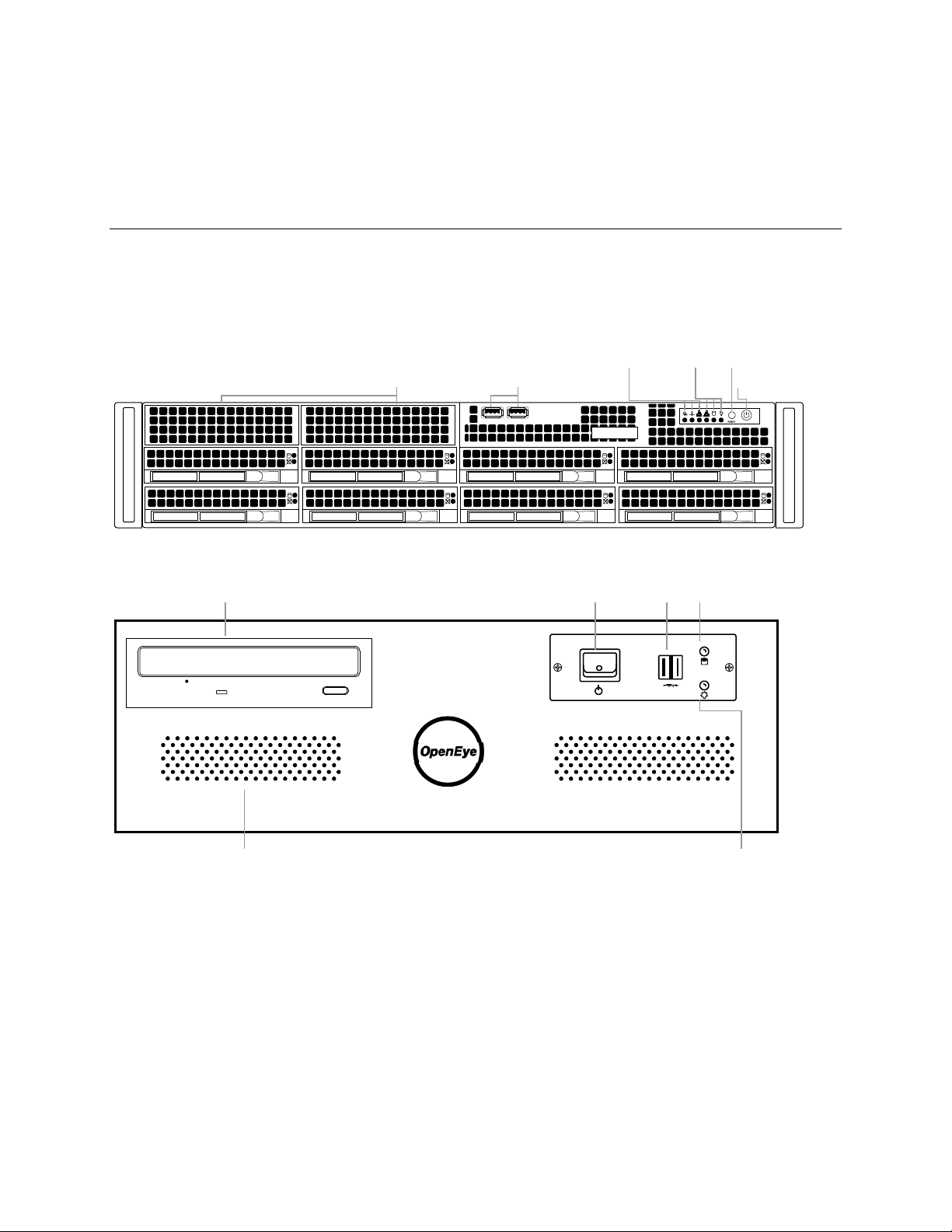
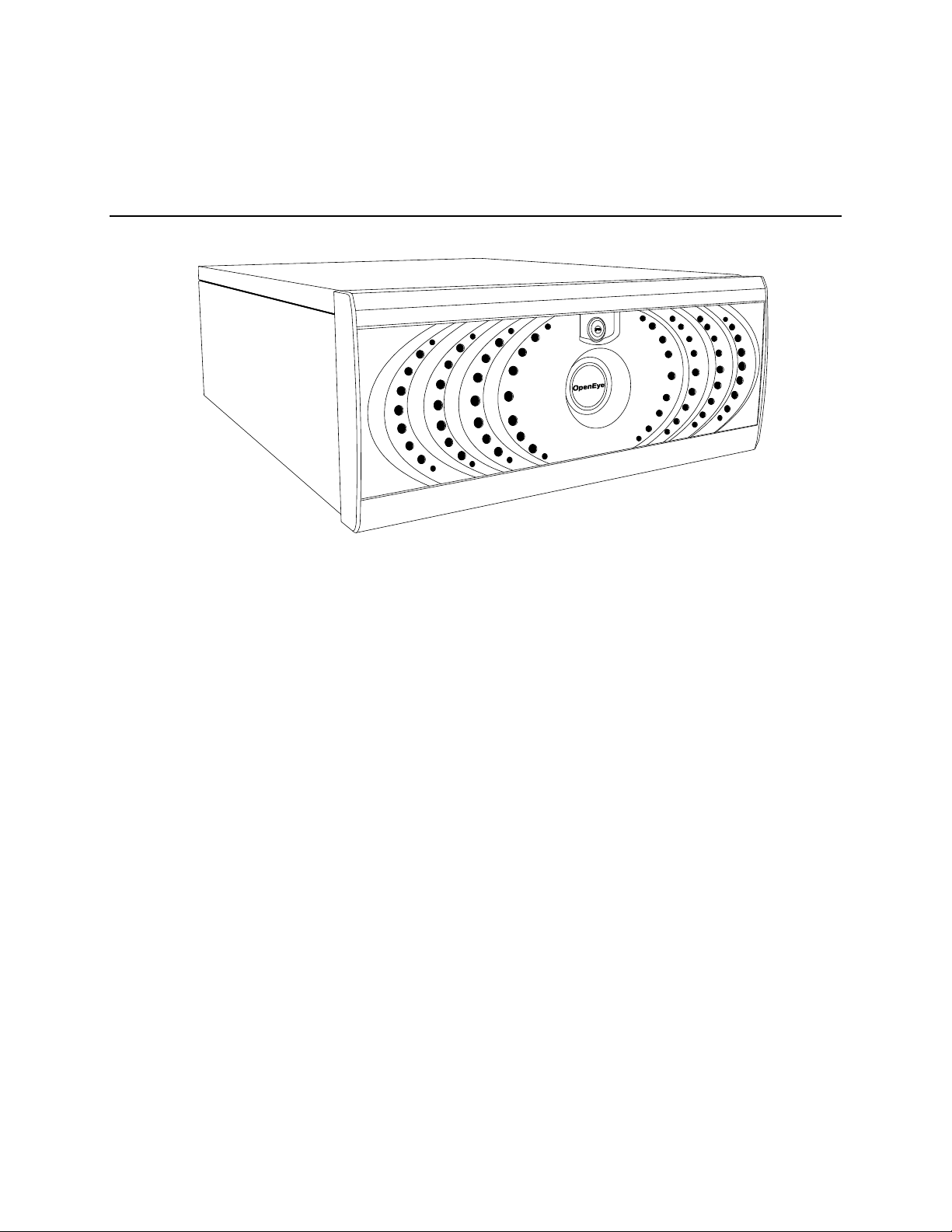
CONTROLS AND CONNECTIONS
Cooling fan intake USB ports Power switch
Reset
LEDs
Power Failure
Fan Failure
NIC2
NIC1
HDD
Power
DVD±RW Drive
Cooling fan intake
Hard drive activity LED
Power LED
USB portsPower switch
FRONT PANEL CONTROLS AND LEDS
The front panel of the NVR contains the devices that will be commonly used for data removal, retrieval,
and backup replacement. The most common components and buttons are shown below:
N2 Front Panel
N3 Front Panel
16
Page 17
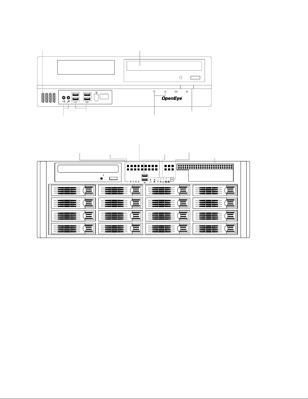
NM Front Panel
Cooling fan intake DVD±RW drive
USB ports Power switch
LEDs
HDD
Power
Speaker out
Microphone in
1 2
!
1
2 43
5 6 7 8
9 10 11 12
13 14 15 16
Cooling Fan Intake
Power Switch
USB 2.0 ports
Power
Failure
NIC 1 and 2
Reset Button
Alarm Mute
System HDD
HDD Tray
Activity LEDs
LEDs
N4 Front Panel
30777AC 17
Page 18

REAR PANEL CONNECTORS
AC power
Optical output
USB USB
NetworkeSATA
USB
Cooling fan
5.1 Surround sound
Line in – line level
Speaker out
Microphone in – not used
HDMI
DVI-I
AC power
Cooling fan
Optical output
USB USB
NetworkeSATA
USB
5.1 Surround sound
Line in – line level
Speaker out
Microphone in – not used
HDMI
DVI-I
The rear panel of the NVR contains the connectors used to attach cameras, sensors, and relays to the
NVR. Below are diagrams that outline the location and description of each connector:
N2 Rear Panel
N3 Rear Panel
18
Page 19

NM Rear Panel
DVI-I
HDMI
Line Out
eSATA
AC power
Optical output
USB USB
NetworkeSATA
USB
Cooling fan intake
5.1 Surround sound
Line in – line level
Speaker out
Microphone in – not used
HDMI
DVI-I
Optical output
USB
USB
NetworkeSATA
USB
5.1 Surround sound
Line in – line level
Speaker out
Microphone in – not used
HDMI
DVI-I
AC power
Cooling fans
N4 Rear Panel
30777AC 19
Page 20

GETTING STARTED
IDENTIFYING INCLUDED COMPONENTS
OpenEye NVRs come with a mouse, keyboard and selected software and cables. Identify the following
components to make sure everything has been properly included with the new NVR. If any of the
following items are missing, contact the dealer to arrange a replacement.
NVR Case Key
(varies by model)
Repair Disc/ Software Disc Power Cable DVI to VGA Adapter
HDD Drives
(Shipped separately
for N4 only)
Mouse Keyboard
Bezel Cover
(N4 Only)
Rackmount Rail Kit
(N2 and N4 Only)
20
Page 21

KEYBOARD SETUP
Left Button
To attach the keyboard to the NVR, plug the end of the Keyboard into a USB port located on the back of
the machine.
MOUSE SETUP
To attach the mouse to the NVR, plug the end of the mouse into a USB port located on the back of the
machine.
The mouse uses a cursor called a pointer. Pointers come in many different shapes but are most
commonly shaped like an arrow.
The mouse has two buttons: a left button and a right button. Quickly pressing and releasing one of
these buttons is called clicking. Sometimes you will need to double-click – or click the same button twice
quickly.
In this manual:
Click means to position the mouse cursor over an item and to single click the left button.
Right click means to position the mouse cursor over an item and to single click the right button.
Double-click means to position the mouse cursor over an item and to click the left button twice.
Select means to position the mouse cursor over a radio button, checkbox, or list item and click on it.
The scroll wheel in between the two buttons is used for added navigation functionality. By moving the
wheel with index finger (scrolling), quickly move through multiple pages, lines, or windows. The wheel
may also function as a third button allowing the user to quickly click or double-click an icon or a selected
item
Scroll Button / Third
Right Button
30777AC 21
Page 22

MONITOR SETUP
The NVR has the following connections available to attach a monitor.
Attach the monitor or monitors to the rear of the NVR using the cable supplied by the monitor
manufacturer. Refer to the monitor manual for detailed information on how to setup and use it.
Note The monitor must be capable of having a minimum screen resolution of 1024 x 768 and
display colors of at least 32 Bit
POWER SETUP
WARNING:
To reduce the risk of electrical shock or damage to the equip m ent:
Do not disable the power grounding plug.
The grounding plug is an important safety feature.
If the electrical plug you are using does not have a ground plug receptacle
contact a licensed electrician to have it replaced with a grounded electrical
outlet.
Plug the power cord into a grounded (earthed) electrical outlet that is easily
accessible at all times.
Disconnect the power from the computer by unplugging the power cord either
from the electrical outlet or the computer.
HDMI Output To TV / Digital Display
DVI-I Output To TV / Digital Display
DVI to SVGA
Connect adapter to DVI output to
connect an analog VGA Monitor
22
Page 23

HARD DRIVE ARRAY (N2 ONLY)
Hard drives in the N2 NVR are arranged top to bottom in the HDD cage. A minimum of one and a
maximum of four hard drives may be installed in the hard drive cage. The hard drive installed in bay one
contains the operating system and if removed will render the NVR inoperable.
Removing a Hard Drive
1. Push the release button for the drive to remove.
2. Pull the release handle outward, sliding the drive tray out of the drive cage.
Inserting a Hard Drive
1. Slide the drive tray into the drive cage.
2. Press the release handle until it clicks, locking the drive tray in place.
HARD DRIVE ARRAY (N4 ONLY)
Hard drives in the N4 NVR are arranged top to bottom in the HDD cage. A minimum of one and a
maximum of sixteen hard drives may be installed in the hard drive cage. The N4 is shipped with the
hard drives in a separate box. To insert the drives, follow these instructions. The drives must be
inserted in order, 1-16 (depending on how many drives you purchased). The drive trays are marked with
the number of their port. See the diagram for the order of the hard drive ports on the N4.
Inserting a Hard Drive
1. Pull the blue button on the drive tray to release the latch.
2. Slide the drive tray into the drive cage.
3. Close the latch until it clicks, locking the drive tray in place.
12
30777AC 23
Page 24

N2 AND N4 RACKMOUNT KIT INSTALLATION
This section provides information on installing the OpenEye 2U and 4U NVRs into a rack unit with the
rack rails provided. There are a variety of rack units on the market which may mean the assembly
procedure will differ slightly. You should refer to the installation instructions that came with the rack unit
you are using.
Preparing for Setup
The box your OpenEye recorder was shipped in should include two sets of rail assemblies, two rail
mounting brackets and the mounting screws you will need to install the system into the rack. Please
read this section in its entirety before you begin the installation procedure outlined in the sections that
follow.
Note These rails are designed to fit a rack between 26 and 33.5 inches deep.
Separating the Secti on of t he Rack Rails
The package includes two rail assemblies in the rack mounting kit. Each assembly consists of two
sections: an inner fixed chassis rail that secures directly to the server chassis and an outer fixed rack
rail that secures directly to the rack itself.
1. Locate the rail assembly in the packaging.
2. Extend the rail assembly by pulling it outward.
3. Press the quick-release tab.
4. Separate the inner rail extension from the outer rail
assembly.
5. Repeat steps for the second rail assembly.
24
Page 25

Installing the Inner Rail E x t e nsions
Each rackmount kit includes a set of inner rails in two sections: inner rails and inner rail extensions. The
inner rails are pre-attached to the chassis, and do not interfere with normal use of the chassis if you
decide not to use a server rack. The inner rail extension is attached to the inner rail to mount the
chassis in the rack.
1. Place the inner rail extensions on the side of the chassis aligning the hooks of the chassis with the
rail extension holes. Make sure the extension faces "outward" just like the pre-attached inner rail.
2. Slide the extension toward the
front of the chassis.
3. Optional: Secure the chassis
with 2 screws as illustrated. (4
screws are provided on N4
models.)
4. Repeat steps for the other inner
rail extension.
Installing the Outer Rac k Rails
Outer rails attach to the rack and hold the chassis in place. The outer rails will extend between 30
inches and 33 inches.
1. Secure the back end of the
outer rail to the rack, using
the leaf springs and screws
provided.
2. Press the button where the
two outer rails are joined to
retract the smaller outer rail.
3. Hang the hooks of the rails
onto the rack holes and if
desired, use screws to secure the front of the outer rail onto the rack.
4. Repeat steps for the other outer rail extension.
Installing the Recorder into a Rack
1. Extend the outer rails.
2. Align the inner rails with the outer rails on the
rack.
3. Slide the inner rails into the outer rails, keeping
pressure even on both sides. When pushed all
the way into the rack, the rails will click into a
locked position (preventing removal without
pressing the quick-release tabs).
30777AC 25
Page 26

N4 FRONT BEZEL INSTALLATION
The N4 is shipped with handles attached to the front of the unit. If you choose to mount the front bezel
to your recorder, you will need to remove the handles and attach the bezel before attaching the
rackmount rails.
1. Remove the two screws from each handle.
2. Install the include bezel clips and fasten with screws.
3. Align and slide the right side of the bezel into the right
clip.
4. Slide the left side of the bezel into the left clip.
5. Lock the bezel by turning the key counterclockwise.
TURNING ON THE NVR
1. Turn on the monitor and any external peripherals (ex. Printers, External Storage Devices, etc.)
connected to the NVR.
2. Turn on the Secondary Power Switch located in the rear of the NVR.
3. Press the Power Switch located on the front of the NVR.
4. The NVR will run a series of self-tests. After two or three minutes, a series of messages may be
displayed as the various hardware and software sub systems are activated. Under normal
circumstances, users should not be asked to respond to these messages. If asked to respond to
the messages (adding a Printer, Monitor, etc for the first time) follow the instructions carefully.
5. Startup is complete when the OpenEye NVR software is finished loading and displays the main
menu screen.
TURNING OFF THE NVR
1. Click Exit on the main menu screen of the NVR software.
2. Select Power Off from the list and click OK. The NVR may take several minutes to shut down
completely.
26
Caution Always be sure to follow the proper procedures when turning off the power to the NVR.
NEVER disconnect the power to the NVR while it is still running or in the process of
Page 27

shutting down. Doing so can cause data loss, fil e corrupt ion, system instability and
hardware failure.
NVR BASICS
SETTING THE TIME AND DATE
1. Exit to Windows by clicking Exit on the Display screen and then clicking Restart in Windows
Mode.
2. Click the Start button > Control Panel.
3. Click Date and Time inside Control Panel.
4. Adjust the Date and Time.
5. When finished, click Apply, then OK, then close all open windows and restart the recorder. Do this
by clicking Start and selecting Restart from the Shut Down menu.
ACCESSING THE DVR UTILITY
Exporting Settings
Exporting settings can help configure multiple NVRs quickly or reconfigure a unit that has been reset to
factory defaults. Some things must be kept in mind when using this feature.
You cannot use this function on:
• NVRs that are different models.
• When upgrading from certain software versions. (This feature cannot be used when upgrading
from v2.x to v3.x)
1. Exit to Windows by clicking Exit on the Display screen then and select Restart in Windows Mode.
2. Click the Start button > All Programs > OpenEye > vFormat.
3. Click Export in the System Setting tool section.
4. Select a location to save the settings file and click Save. The DVR Utility will export the NVR
settings and automatically close.
30777AC 27
Page 28

Importing NVR Settings
Sensor Status
Relay Outputs
Screen Division buttons
Connected
User Details
1. Exit to Windows by clicking Exit on the Display screen then and select Restart in Windows Mode.
(See the Display screen section later in this chapter)
2. Click the Start button > All Programs > OpenEye > vFormat.
3. Click Import in the System Setting Tool section.
4. Select the location of the settings file to import and click Open.
5. Click Yes to import the data file.
DISPLAY SCREEN
Each time the recorder star ts, the program defaults to the Display scre en . The following diagram
outlines the buttons and features used on the D i spl ay screen. You should become familiar with these
options as this is the screen that will be displayed the majority of the time.
Current Date / Time
CPU meter
Opens:
• Search
• Setup
• Backup
• PTZ Controller
28
Users
Page 29

CPU Meter
Use the CPU meter to monitor the system resources on your recorder.
• GREEN - System configuration OK
• YELLOW - Caution; evaluate system configuration and consider
decreasing system loading
• RED - System configuration has been exceeded which may affect
stability; decrease system loading or upgrade system with CPU
performance package.
Live Camera Options
Right-click a camera on the Display screen to
display these options:
• Full Screen
• Instant Recording
• Search In Live
30777AC 29
Page 30

CAMERA VIEW
I
Camera No. and Name
Recording Status
Special Recording Type
Recording Status Indicator
The camera status for each camera is displayed in the upper right corner on the Video Display Area.
The following are the different states for each camera:
Recording Displayed when the camera is currently being recorded to the recorder.
Motion Detection Displayed when a camera (set up for motion detection) detects motion.
Display Displayed when the camera is currently not being recorded to the recorder.
Special Recording
There are two types of Special Recording. Text is displayed on the camera indicating what type of
Special Recording is activated.
SENSOR
Sensor is displayed when a sensor, associated with a given camera, is activated.
INSTANT
Instant Recording is a manual activation of the recording for the selected camera. Regardless of the
recording method, Instant Recording will start the camera recording and also flag the video for future
searches using the Index Search feature. INSTANT is displayed when a user activates the instant
recording option. Double right-click the video display to activate and deactivate the Instant Recording
option.
30
Page 31

EDIT LIVE VIEW CHANNELS
By default, the recorder only allows live video from four network channels at one time on the local
server. This protects the processor resources for recording data. The Radius software allows you to
view live video from multiple recorders at once and with the same limitations that the recorder has on
the number of live IP based video channels. If more than four channels of live video are required on the
local server, you can enable the recorder to show up to 16 channels. Be aware that displaying 16
channels of live IP based video is resource intensive and may dramatically impact system performance.
To enable the recorder to view 16 channels of live video:
1. Click Exit on the display screen and select Restart in Windows Mode.
2. Double-click the Edit Live View Channels icon on the desktop.
3. If you wish to continue, confirm the two warning windows.
The live view display will switch to 16 channel mode. To return the recorder to 4 channel mode, run the
utility again using the same instructions.
SCREEN DIVISION BUTTONS
Note When viewing live video from Network Cameras, only 4CH will display at one time. If more
live view channels are required on the local server, see the Edit Live View Channels
instructions.
1st Four Cameras View – Di s play s camer as 1-4 in the Video Display Area. To return to a
different Multi-Camera View, select a different Screen Division option from the Screen Division
menu.
2nd Four Cameras View – Displays cameras 5-8 in the Video Display Area. To return to a
different Multi-Camera View, select a different Screen Division option from the Screen Division
menu.
3rd Four Cameras View – Displays cameras 9-12 in the Video Display Area. To return to a
different Multi-Camera View, select a different Screen Division option from the Screen Division
menu.
4th Four Cameras View – Dis play s cameras 13-16 in the Video Display Area. To return to a
different Multi-Camera View, select a different Screen Division option from the Screen Division
menu.
Full Screen
viewable area on the monitor. When this is selected, no menu options are visible. You can
activate the Full Screen Option by clicking on the Full Screen button within the Screen Division
menu. You can deactivate Full Screen mode by right clicking on the screen.
Auto Sequence
and then the Loop button will sequence through 1A, 2A, 3A, 4A and then repeat.
– The Full Screen Option allows you to view the Video Display Area using the entire
– Sequences through the Screen Divisions sets. For example, selecting the 1A
30777AC 31
Page 32

Dual Monitor Camera Displa y Menu
When dual monitors are enabled, you can adjust the camera display for live view on the secondary
display. Move the mouse to the top of the screen and the camera display menu will appear.
Custom Live View Divisions
Customize your Live View screen by changing the order of the cameras. Each screen division can be
individually customized but a camera can only be displayed once in each group view.
Create custom live view divisions:
1. On the Display screen click Setup, and then click General.
2. Click Sequence Setting.
3. Drag and drop cameras from the Channel List to the desired location within the Division Group.
Channel
Division Group
32
Page 33

SETUP OPTIONS
Setup Options
SETUP OVERVIEW
The Setup options allow you to optimize your recorder by adjusting things like camer a nam es, restart
schedules, recording schedules and more. It is extremely important that you setup your recorder
correctly for several reasons.
• Recording Schedules – Increase the amount of pertinent recorded video that is saved on the
recorder by optimizing the recording schedule. Optimize the type of recording done by adding
motion detection to this as well, again increasing the amount of useful video.
• Camera Naming – Name each camera so the location can be easily identified and include any
other pertinent information that may be helpful when viewing it on the Video Display Area.
• Configure Network Cameras – Connect to and configure cameras that are available on the
network the NVR is connected to.
SETUP SCREEN OVERVIEW
30777AC 33
Page 34

NETWORK CAMERA SETUP
Connecting a Network Device
Connecting Manually
1. From the Live View screen, click Setup.
2. Click Network Cameras.
3. Select your network device from the Device Type list.
4. Type a Device Name.
5. Type the IP/URL address, Port#, User ID and Password of the device.
6. Click Add.
7. Click Apply.
8. Proceed to Assigning a Network Device to a Channel.
Connecting with Find Cameras
1. From the Live View screen, click Setup.
2. Click Network Cameras.
3. Click Find Cameras to automatically find all connected Network cameras.
4. Select the check box next to the desired camera.
5. Type the User ID and Password of the device.
6. Click Get Device.
7. Click Apply.
8. Proceed to Assigning a Network Device to a Channel.
34
Page 35

Assigning a Network Device to a Channel
1. From the Live View screen, click Setup.
2. Click Network Cameras.
3. Click the Channel Setup tab.
4. Click an available channel on the Channel List.
5. Type the desired Position Name.
6. On the Select Device list, select the appropriate network device added previously.
7. If the device has PTZ capabilities, select the PTZ Camera check box to enable.
8. If the device displays wide screen video, select the Wide Screen check box to allow it to display
properly.
9. If supported, select the Use Network Camera Motion Detection check box.
10. Select Intensive Motion, Intensive Sensor, and/or Intensive Instant to increase the recording
rate on an event.
11. Click Apply to save your selection s.
30777AC 35
Page 36

Assigning Dual Streams
Dual stream support enables you to take advantage of two different streams from an IP camera. One
stream can be high definition forensic video, while the other stream can be a lower resolution for live
display. This allows for OpenEye Radius or Remote to display more cameras while utilizing lower
bandwidth and less CPU usage.
The second stream is used for motion detection in the server, which lightens the processing load for
centrally-managed motion detection configurations. Dual Stream can be configured to allow for the
continued use of Hot Spot when desired.
Dual streaming functions are limited to cameras that support this feature.
1. From the Live View screen, click Setup.
2. Click Network Cameras.
3. Click the Channel Setup tab.
36
4. Click an available channel on the Channel List.
5. Type the desired Position Name.
6. On the Select Device list, select the appropriate network device added previously.
7. If the device has dual streaming capabilities, choose the appropriate streams in the Main Stream
and Sub Stream drop-down menus.
8. Click Apply to save your selection s.
Page 37

Controlling a PTZ camer a
Displays
Channel
Set Presets,
The PTZ controls within the recorder allow for powerful control over the cameras. This can be extremely
beneficial by increasing the usefulness of the recorded video. Using the PTZ controls you can create
custom preset configurations that can continuously sweep across large areas.
Note PTZ setup and control through an encoder is only available for supported video encoders with
a PTZ RS-485 pass-through.
The OpenEye recorders provide control for a PAN/TILT/ZOOM camera in two different ways.
• Use the Graphical PTZ Controller that appears when the PTZ button is clicked on the Display
screen.
Using the Graphical PTZ Cont roller
1. Use the Arrow buttons to control the direction of the
PTZ camera.
2. To select a new camera, click the video display of a
different camera on the Display screen display.
Note Eight directions are available only for select
cameras. Only four of the PTZ Control buttons
work for all protocols (UP, DOWN, LEFT,
RIGHT).
Arrow buttons
Current
Camera
Note The Advanced menu panel on the graphical
PTZ controller can be used to set PTZ preset
positions (on supported cameras), as well as
move to presets upto 254.
Move To
Preset
Positions 1-10
Opens & Closes
the Advanced
Panel
and Move to
Presets 11-254
30777AC 37
Page 38

Assigning Audio Channels to a Networ k De vi c e
1. From the Live View screen, click Setup.
2. Click Network Cameras.
3. Click the Audio Setup tab.
4. Click an available audio channel on the Channel List.
5. On the Select Device list, select a network device added previously.
6. To record the network audio select the Record Network Audio check box. The audio channel will
be available on the search screen.
7. To access the audio channel from the Live View screen, select the Enable Network Video in Live
View check box.
38
Page 39

Camera Configuration
The Camera Configuration tab displays information on all cameras connected to the OpenEye recorder.
Disable/Enable Live Video
• To disable the live view of a network device (to conserve resources), unselect the check to the
left of the Camera Name. The camera channel will display “Non-Decoding Mode Enabled” on a
black background
• To enable the live view of network device, sel ect the check box next to the Camera Name that
you want available for live video display.
Displaying More Columns
The Camera Configuration tab can be customized to display the information you use most. Click Select
Column to add or remove specific columns.
Capture FPS
Record FPS
Schedule
Manufacturer
Model
IP Address
Port Number
Resolution
Record FPS
Frame Rate
Codec
Quality
PTZ
30777AC 39
Page 40

Accessing the Configuration Menu
Use the OpenEye interface to access basic network device menu functions.
1. From the Live View screen, click Setup.
2. Click Network Cameras.
3. Click the Camera Configuration tab.
4. Highlight the desired camera.
5. Click Setup Network Device.
NVR Registration and Upgrade
Have the following information available before registering the NVR upgrade.
Product Serial Number: This may be the Product Serial Number displayed on the product sticker on the
left side of the recorder; or the the unique Product Serial Number provided with the purchase of
additional channel linceses.
System ID: The System ID is a number that is generated by the OpenEye unit. This is a unique code
generated using the MAC address of the recorder.
Locating the System ID
1. From the Display screen, click Setup.
2. Click Network Cameras.
3. Click the License tab.
40
Page 41

Obtaining the License Key
1. Open an Internet browser and go to: http://activate.openeye.net/nvr
2. Enter the Product Serial Number and System ID.
3. Click Submit.
4. Verify the information, and click Next.
5. The Unlock Code provided will need to be entered into the License Key field on the recorder.
Note Both the System ID and the Unlock Code are case sensitive.
Note We recommend printing the registration page with the Unlock Code for later reference.
Unlocking the Upgrade
1. Return to Setup > Network Cameras > License.
2. Enter the Unlock Code generated by the OpenEye Registration Site into the License Key box.
3. Click Register and confirm that the new License Key is listed in the Channel Connection License
box.
4. Click OK.
5. Click Apply.
6. Click Exit Setup.
Unlocking Additional Ne t w ork De vi ces
Follow the instructions above for Registration and Upgrade to unlock any additional network devices.
30777AC 41
Page 42

MOTION SETUP
Display full screen
motion event
Beep on
sensor event
The recorder allows the user t o adjust se veral different Motion Settings and create motion detection
areas.
video pop up on
motion event
Display full screen
video pop up on
Create a Motion Area
Reduces Analog Signal Noise from Motion Detection
1. From the Display screen, click Setup.
2. Click Motion.
3. Select a camera from the Select Camera list.
4. Select the Detect Detail Motion Area check box.
5. Click Clear.
6. Click Advanced Motion Area Setup.
7. Click a Motion Detection Area shape button.
8. Drag the mouse over the camera image.
Note To create a polygon shape, click the mouse at each
point and double-click to close the shape.
9. Click OK.
10. Move the sliders to adjust motion sensitivity and the noise
filter.
11. Define the pre-alarm and post-alarm recording time for a motion event.
Pre Alarm – 0 - 120 Seconds [The number of seconds the recorder records before motion is detected—
to ensure any motion occurring between I-frames is captured, set to a value greater than 0]
Post Alarm (MOTION) – 0 - 120 Seconds [The number of seconds the recorder records after it stops
detecting motion]
42
Page 43

Enable Sabotage Detection
The Camera Sabotage Detection feature will notify users that the field of vision of a camera has been
compromised, abruptly changed, or dete ct s signi fic ant vibr at ion.
To enable Sabotage Detection:
1. Select the Enable Sabotage Detecti on check box.
2. Set the threshold percentage to reduce false alarms.
3. Select the Beep on Detect che ck bo x – or – select a n output
Relay to activate on detection.
30777AC 43
Page 44

GENERAL SETUP
Display
IP Camera Key Frame Decoding
This will only show key frames (I-frames) in the live view in order to reduce the CPU load. Enabling this
funciton does not impact recorded or remote streami ng vide o .
Use Full Screen
Stretch the OpenEye interface to use the full monitor screen based on the resolution set in Windows.
Display Size
Select from available monitor display sizes. Use to correctly display video on wide screen monitors.
Function
Beep on Login Fail
Enables the recorder to beep continuously in response to a failed login attempt. Only an authori zed
login will stop the beeping.
Sequence Setting
Allows the video out picture to aut om ati cal ly cycl e thro ugh ch annel s at a set speed. Example: .Cycle
through channels 1-6 at four-second intervals.
Dual Monitor
Enable a second monitor connected to the recorder. See Connecting a Second Monitor for complet e
instructions.
Hybrid Sensor Setup
This interface is used to link Hard Contact Sensor Inputs from supported Network Devices to the
recorder software.
44
Page 45

Voice Warning
Open Sound File
Test
The recorder allows users to play a sound file when either a Motion event or Sensor event occurs. This
file can be a custom created sound file that is unique to the application. The selected WAV file is pla yed
through speakers attached to the recorder.
1. Click the Open Sound File icon to browse for a WAV file. The selected file will display in the box
on the left.
2. Click the Test icon to verify the audio file.
3. Select Motion Event and/or Sensor Event to trigger the audio file.
Hybrid Sensor Setup
This interface is used to link Hard Contact Sensor Inputs from supported Network Device s to the
recorder software.
The Network Device List is a list of available IP camera devices that have sensors enabled. When a
device is selected, the lower table will populate with a list of the sensors for the device.
• Click the arrow next to a sensor or relay to display the number of the sensor on the recorder.
You can then associate a sensor or relay from the recorder with a sensor or relay on the
network device.
30777AC 45
Page 46

Connecting to a Wide Screen Displa y
1. Click Exit on the Display screen and select Restart in Windows Mode.
2. Right-click the Desktop and select Screen Resolution.
3. From the Resolution list, sele ct the proper solu tio n of the connec ted dis pla y.
Tip Refer to the display documentation for the proper resolution settings.
4. Click Apply, confirm the change, then click OK.
5. Double-click the OpenEye Server icon on the Desktop.
6. Click Setup on the Display screen and then click General.
7. Under Display Settings, select Use Full Screen.
8. Click Apply then click Exit Setup.
Connecting a Second Monitor
All recorders can support two connected monitors. If a second monitor is connected to the recorder,
follow these steps to enable the Dual Monitor setting s.
1. Click Exit on the Display screen and select Restart in Windows Mode.
2. Right-click the Desktop and select Screen Resolution.
3. Click the secondary display screen and from the Multiple displays list cli ck Extend these
displays.
Tip If a second display is not shown click Detect; if the second display does not appear, verify
that the second monitor is properly connected.
4. Click Apply, confirm the change, then click OK.
Tip Refer to the display documentation for the proper resolution settings.
5. Double-click the OpenEye Server icon on the Desktop.
6. Click Setup on the Display screen and then click General.
7. Under Function, select Dual Monitor.
8. Click Apply then click Exit Setup.
Setting Up Dual Monitor Preferences
When using dual monitors on the recorder you can set the Live View, Search and Setup windows to
open on either the primary or secondary monitor.
1. Click Dual Monitor Setup to configure what will be displayed on the second monitor.
2. Select the appropriate check boxes to open Live View, Search and Setup on the Primary or
Secondary monitor.
Note Live View will always default to the Primary monitor. When the Secondary monitor is selected
for Live View, the cameras will display full screen on the secondary monitor.
46
Page 47

Volume
Enable All
Cameras
Enable
The volume control allows fine tuning of the volume settings on the recorder.
Volume Options:
• Device/Speakers – Used to adjust the volume for al l sound com ing fr om the system ’ s
speakers.
• System Sounds – Used to adjust the volume for the system sounds exclusi vel y.
Auto Sequence Setting
Auto Sequencing is available either in the Display screen when Auto Sequencing has been enabled.
Auto Sequencing conveniently displays video channels at specif ied inter va ls and seq uen ce s through
each selected channel.
Sequencing
Select interval
between switching
Custom Mode
Create non-standard screen di vis ion la yout s.
Skip 0 FPS Channel
Sequence skips cameras with no video signal.
Create Custom Auto Sequence
1. From the Display screen, click Setup.
2. Click General.
3. Click Sequence Setting.
4. Click individual cameras in the left pane or click Select All to include all cameras in the sequence.
5. Select an Interval time (in seconds) to display each screen in the sequence.
6. Select screen division options for appropriate cameras.
7. Click OK, click Apply, then click Exit Setup.
30777AC 47
Page 48

SCHEDULE SETUP
Single Day Selection /
Multi Day selection
Recording schedule window
Recording Schedule
The Recording Schedule window allows you to create different recording schedules based on the day,
time, and type of recording desired. In addition, this window contains the System Restart options.
Create Special
Day recording
Create a Recording Schedule
48
Recording mode options
Select a day to begin creating the schedule for -or- click Single Day Selection, enabling Multi Day
Selection, to create the same schedule for multip le day s.
Highlight the Time-Blocks within the Recording Schedule window for the cam era( s) selected to
schedule. Once the desired Time-Blocks are highlighted, click a Recording Mode button. The TimeBlocks should now appear Blue for Motion, Yellow for Continuous and White for No Recording.
Note Leave cameras recording with Sensor Detection set to No Recording for the specified time
block(s).
Emergency IP setup
Page 49

Sensor Schedule
Single Day Selection /
Multi Day selection
Create Special
The Sensors will supersede all other types of recording modes (Motion and Continuous). Regardless of
the recording schedule of a particular camera, if a sensor event occurs the associated cameras will
begin recording as a Sensor Event. Sensor Recordings will be flagged and searchable using the Index
Search Mode. Cameras are associated to sensors in the Camera Setup menu.
Sensor schedule window
Day Sensor
schedules
Alarm options
Emergency IP setup
Create a Sensor Schedule
Click Schedule and then and then select the Sensor option. Select a single day or click Single Day
Selection to include multiple days in the sch edu le.
Highlight the Time-Blocks within the Recording Schedule window for the sensor(s) to enable and
schedule. Once the time blocks are highlighted click Enable. The time block will now appear red.
30777AC 49
Page 50

Scheduling Alarm Event s
There are three types of Alarm Events:
• ALARM EVENT: This option logs the Alarm Events on the local server.
• CENTRAL STATION: This option sends a Map Alarm to Radius.
• EMERGENCY AGENT: This option sends the Alarm Event to the Emergency Agent software.
Motion can be designated as an alarm event. Often motion does not need to be treated as an Alarm
event. For example: During work hours, motion that occurs is expected and should not be treated as an
alarm. However, after business hours, any motion that occurs could be treated as an alarm.
1. From the Display screen, click Setup.
2. Click Schedule.
3. Select either Recording or Sensor.
4. Highlight time blocks in the schedule that have been set to Motion (or Sensor) and click the desired
Event buttons (Alarm Event, Central Station, Emergency Agent). A corresponding let ter will display
in the selected time blocks.
Emergency Agent Schedul e
Video recording triggered by motion or sensor events can be sent to the Emergency Agent software.
1. Enable the Emergency Agent Event. (see Scheduling Alarm Events above).
2. Enter the IP Address of a PC running the Emergency Agent software under Emergency IP.
3. Select the check box next to the IP Address to enable it. Only one IP Address is supported at a
time.
4. Enter the recording duration (in seconds) in the Emergency Time box.
Tip See the Emergency Agent chapter for detailed information on setting up the Emergency
Agent software.
50
Page 51

Special Day Schedule
You can create days that have a unique recording schedule. For example: Holidays, Special Events,
etc.
Special Day Mode / Normal Day Mode
Date Selector (Calendar)
Configured Special Days List
Creating/Editing a ‘Special Day’ Schedule
1. Click Normal Day Mode t o enable the Special Day Mode.
2. Select a day by typing the date or clicking the down arrow to select the date from a calend ar .
3. Highlight the time-blocks within the Recording Schedule window for the camera(s) selected. Once
the desired Time-Blocks are hi ghli ghte d, click a Recording Mode button.
4. When finished creating the schedule click Save Special Day.
Note The special day should now appear as a date in the Special Day Schedule. To edit it, highlight
it on the list and repeat steps 3 and 4 above.
Deleting a ‘Special Day’ Schedule
1. Select a date from the Special Days list.
2. Click Delete Special Day.
30777AC 51
Page 52

System Restart Setup
Restart Setup allows you to define a schedule wherein the recorder automatically restarts according to
specified parameters.
Create System Restart Schedule
1. From the Display screen, click Setup.
2. Click Schedule.
3. Click Restart Setup.
4. Select Enable for each day of the week that a restart is desired.
5. Specify the time of day to schedule the system restart.
6. Select either Restart or Off.
Note If Off is selected, the recorder will shut down at the specified time but not restart.
7. Click OK, click Apply, then click Exit Setup.
52
Page 53

NETWORK SETUP
way audio between
Remote Client Ports
Network Setup allows the user to adjust settings such as Ports, setup emergency PPP information for
use with the Emergency Agent and enable Remote Access.
Use with Emergency Agent
Time Out Value When attempting to connect to the recorder, if the connection does not succeed during
the timeout period (seconds), the connection will be terminated.
Emergency Port Used to connect with the Alarm Monitor software.
Center Port Used to connect with the OpenEye remote software (Remote, Radius, MDVR). This port
must be specified in the remote software to connect to the recorder.
Note Center Port 1025 is not available.
Image Port Used to transfer the video to the OpenEye remote software.
Search Port Used to transfer search information to the OpenEye remote software.
Note If connecting to the recorder through a firewall, the above ports must be open to incoming and
outgoing traffic.
Health Check Port Enables Radius to receive information regarding the health of the recorder.
Enable twoDVR and Remote Client
30777AC 53
Page 54

ADMINISTRATIVE SETUP
Select
Log
Select
Log Data Display
Disk Management
The Disk Management window is a native Windows function. This window displays the partition scheme
and health status of the Hard Disk Drives in the recorder. This window is often used to troubleshoot a
recorder, or verify the amount of Hard Drive storage inst al led. For more information about Disk
Management, consult a Windows 7 manual.
Export Log Data (1 to 7 days)
54
Page 55

Setting Up DDNS
Dynamic Domain Name System (DDNS) is a service that provides a static address to simplify remote
connection to the recorder. This service is most useful for installations where the WAN (public) IP
address is dynamic (changes from time to time). Most public IP addresses are dynamic unless a static
address has been specifically ordered from the internet service provider.
Enable DDNS
To enable this functionality of the recorder, follow the steps below:
1. Click Setup on the Display screen and log in as Administrator if prompted.
2. Click Administrative.
3. Click Program Management (ETC) and enter the Administrator password when prompted.
4. Click Show (to the right of Dynamic DNS Configuration).
5. Select Enable DDNS.
6. Enter the User Name, Password, and Hostname specified on
the DDNS document shipped with your recorder.
7. Click OK, then close the Program Manager window.
Note Ensure the recorder has an IP address by setting it
statically. The Network settings may need to be changed. If
you are not sure of the correct values, contact the individual
or department responsible for network administration at the
site.
Set the IP Address
The IP address of the recorder is set in Windows; to set the IP address follow the steps below:
1. On the Display screen, click Exit and choose Restart in Windows Mode.
2. Right-click My Network Places and click Properties.
3. On the General tab, click Internet Protocol (TCP/IP) and then click Properties.
4. Select Use the following IP address.
5. Enter values for the IP Address, Subnet Mask, and Default Gateway (these may be specified by the
department responsible for network administration).
a. IP Address: The first three sets of numbers should match the router’s local IP address
and the last set should be a unique number between 1-254.
b. Subnet Mask: This should match the router’s setting (commonly 255.255.255.0 for 192.X
addresses and 255.0.0.0 for 10.X addresses).
c. Default Gateway: This is the router’s internal IP address. Once DDNS is configured, the
router the recorder connects to will need to have port forwarding configured.
For further instruction on this process, visit
Once DDNS and port forwarding have been configured, the recorder will be accessible from any remote
site by entering the HOSTNAME into the address bar of Internet Explorer or the IP Address field in
remote software.
http://openeye.net and search for “Port Forwarding.”
30777AC 55
 Loading...